Table of Contents
Advertisement
Advertisement
Table of Contents

Related Manuals for SKF Multilube


Summary of Contents for SKF Multilube
- Page 1 Operation and service manual SKF Multilube Central lubrication system...
-
Page 2: Table Of Contents
General information on centralized lubrication system ......................... 1 Multilube-central lubrication system..............................1 Diagram for Heavy-system................................2 Diagram for Twinheavy-system ................................ 3 Multilube pumping unit ........................4 General description ..................................... 4 Design........................................4 Operation ......................................5 Filling the lubricant reservoir of the pumping unit ......................... 5 Technical specification .................................. -
Page 3: General System Description
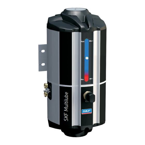
SKF Multilube-central lubrication system SKF Multilube system is a single- or dual-line (Heavy- or Twinheavy) central lubrication system, in which the lubricant is pumped through piping to the dosers. Dosers feed the pre- set amount of lubricant to the lubrication points. -
Page 6: Multilube Pumping Unit
SKF Multilube pumping unit General description The pumping unit is designed for pumping lubricant into central lubrication system. Design Pumping unit comprises of a body (pos. 1) and a lubricant reservoir (pos. 2). The body comprises of a pump element (pos. 3), an electric motor (pos. 4), a line valve (pos. -
Page 7: Operation
Operation When pressurization begins, the control starts the pump and opens the line valve. In pres- sure switch operation the pump stops, when the pressure switch closes and restarts, when the pressure switch opens. After the set pressurization time, the control stops the pump and pressure discharges from the line to the lubricant reservoir. - Page 8 Caution Filter (15) of the filling connector has to be cleaned regularly and replaced if necessary.
- Page 9 Removing air from the pumping unit Remove air from the pumping unit, if there is air mixed with the lubricant e.g. in connection with the filling of the lubricant reservoir. Removing air from the pumping unit: 1. Disconnect the main line connections. 2.
-
Page 10: Technical Specification
Technical specification 4 l reservoir 10 l reservoir Max. output 13 g/min 13 g/min Reservoir 10 l Max. pressure 250 bar / 3626 psi 250 bar / 3626 psi Operation temperature range -30 C … +70 - 30 C … +70 °... - Page 11 MLP-4-2-24-JB103-PS Pressure control unit, built-in pressure switch User interface, JB-103 Power input, 24 V Number of lines, 2-line system Lubricant reservoir volume, 4 l MultiLube pump Spare parts See MLP-pumping unit spare parts (drawing no. 361304 in the next page).
-
Page 13: B-Doser Groups, Heavy-System
B-doser groups, Heavy-system General description Note Numbers in brackets are part numbers of drawings 461780 in the page 16. A doser group consists of a mounting rail (pos. 1) and one or several dosers (pos. 2) fas- tened to it. The mounting rail divides the lubricant to the dosers, which feed the adjusted amount of lubricant to the lubrication points. -
Page 14: Adjustments
Adjustments Adjustments of B6-doser 1. Turn open the pipe connector of the doser’s lubrication piping outlet. 2. Turn open the locking nut in the upper part of the doser. 3. Adjust the dosage by turning the adjustment screw located above the locking nut. 4. - Page 15 Symbols Tabel 2. The symbols of dosers BX-xxx-Y-Z-U Abbreviation Description Lubrication system type, B Doser size, size 1 Doser size, size 2 Doser size, size 3 Doser size, size 4 Doser size, size 5 Doser size, size 6 xxx: R1/8 Fastening of doser to mounting rail R 1/8”...
- Page 16 Tabel 3. Doser codes Doser Code B1-R1/8-ZN-4 11391000 B2-R1/8-ZN-4 11391050 B3-R1/8-ZN-4 11391100 B4-R1/8-ZN-4 11391150 B5-R1/8-ZN-4 11391200 B6-R1/8-ZN-4 11391250 B1-R1/8-ZN-6 11391300 B2-R1/8-ZN-6 11391350 B3-R1/8-ZN-6 11391400 B4-R1/8-ZN-6 11391450 B5-R1/8-ZN-6 11391500 B6-R1/8-ZN-6 11391255 Tabel 4. Symbols of mounting rails BPLD-XX-YY Abbreviation Description Mounting rail, Base Plate Lubrication system type, LD 2-place mounting rail 0202...
- Page 17 Example: BPLD-04-ZN Mounting rail material, zinc-coated and yellow-passivated steel Mounting rail size, 4-place mounting rail Lubrication system type, LD Mounting rail, Base Plate Lubricant inlet, pipe connector Ø 8 mm Tabel 5. Mounting rail codes Mounting rail type Code BPLD-0202-ZN 11392310 BPLD-0303-ZN 11392320...
-
Page 19: Smg-Dosers, Twinheavy-System
SMG-dosers, Twinheavy-system General description SMG-2 doser feeds the preset amount of lubricant to one to eight (1 – 8) lubrication points. Design The doser includes a disk valve (pos. 1) and a dosage cylinder (pos. 3) which is equipped with sealed piston (pos. -
Page 20: Adjustment
Dosers with one outlet The doser with two outlets is modified to doser with one outlet by removing the disk valve and the lubrication outlet connection and replacing them with blocking plug (pos. 7). During normal sequential operation, doser with one outlet feeds the lubricant in turns to lubrication outlet connection and to one of the main lines. -
Page 21: Technical Specification
DOSAGE (g) (grease density 0,88 g/cm3) ADJUSTMENT GRAPH max 1,32 min 0,13 9 10 11 12 13 14 15 16 17 18 19 mm/turn TURNS OF ADJUSTMENT SCREW / L Technical specification Technical specifications Tabel 6. Technical specifications of a doser group Value Range Unit... - Page 22 Symbols Tabel 7. The symbols of dosers SMG-X-Y-zz Abbreviation Description SMG: The type of the lubrication system, SafeMobeGrease Number of the lines, dual line Doser body size 1; 2 outlets Doser body size 2; 4 outlets Doser body size 4; 8 outlets Doser material, zinc-coated and yellow-passivated steel Example:...
-
Page 24: Operation Of User Interface Jb-103
Operation of user interface JB-103 There are a SET-button and three LED-signals 1, 2 and P on the user interface JB-103. Normal functions Button for lubrication Depending on the lubrication program status the SET-button can be used for different func- tions: Lubrication program status Functions... -
Page 25: Functions
SET-button for 5 seconds until all three LED-signals are lit. Note To exit setting mode without saving settings, switch off operating voltage for Multilube for a moment. Setting the maximum pressurization time Press SET-button for 10 seconds in normal operation mode until the LED-signal 2 begins to flash quickly. - Page 26 SET-button for 5 seconds until all three LED-signals are lit. Note To exit setting mode without saving settings, switch off operating voltage for Multilube for a moment. Setting of the lubrication system Press SET-button for 15 seconds in normal operation mode until the LED-signals 1 and 2 begin to flash quickly.
-
Page 28: Multilube-System Monitoring
3. Check that lubricant comes out of the lubrication pipes and hoses. 4. Connect the lubrication pipes and hoses to the lubrication points. If lubricant does not come out of lubrication pipes or hoses, see Multilube / Troubleshooting. B-dosers Steps 1. -
Page 29: Choosing The Lubricant
Note that in addition to the application, also operating temperature, rotation speed and operating environment are relevant factors in choosing the lubricant. For more information on pumping of different lubricants, contact Oy SKF Ab. -
Page 30: Multilube-System Troubleshooting
SKF Multilube-system troubleshooting System troubleshooting User interface does not operate Operation disturbance Cause of operation Solution disturbance Display and LED signals of No supply voltage on Check supply voltage. user interface are not lit. pumping unit. User interface triggers an alarm... -
Page 31: Warnings
A lubrication point gets too little lubricant or nothing at all Operation disturbance Cause of operation Solution disturbance The rotation of the bearing The dosage adjustment of Increase the dosage. makes noise, is trembling or the doser is too small. the temperature is rising. -
Page 32: Contact Information
Contact information Oy SKF Ab P.O. BOX 80 40951 MUURAME Finland Tel. +358 207 400 800 Fax. +358 207 400 899 skf-lube@skf.com www.skf.com...
Need help?
Do you have a question about the Multilube and is the answer not in the manual?
Questions and answers