Table of Contents
Advertisement
Advertisement
Table of Contents

Related Manuals for Jet JWBS-16B


Summary of Contents for Jet JWBS-16B
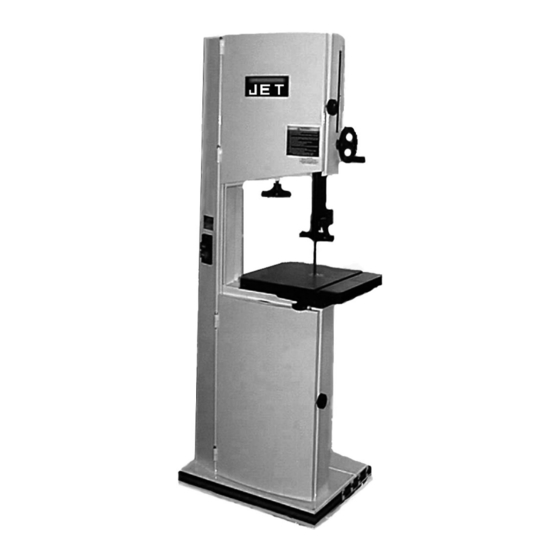
- Page 1 This Manual is Bookmarked Operating Instructions and Parts Manual 16-Inch Woodworking Band Saw Model JWBS-16B WMH TOOL GROUP, Inc. 2420 Vantage Drive Elgin, Illinois 60124 Part No. M-708749B Ph.: 800-274-6848 Revision A 03/08 www.wmhtoolgroup.com Copyright © 2008 WMH Tool Group, Inc.
-
Page 2: Warranty And Service
WMH Tool Group Authorized Service Centers can authorize warranty repair, assist you in obtaining parts, or perform routine maintenance and major repair on your JET® tools. For the name of an Authorized Service Center in your area call 1-800-274-6848. -
Page 3: Table Of Contents
Table of Contents Warranty and Service... 2 Table of Contents... 3 Warning ... 4 Introduction ... 6 Specifications ... 6 Grounding Instructions ... 7 Unpacking ... 8 Contents of Shipping Container ... 8 Assembly and Setup ... 9 Base Support Extension ... 9 Adjusting Blade Tension... -
Page 4: Warning
Warning 1. Read and understand the entire owner's manual before attempting assembly or operation. 2. Read and understand the warnings posted on the machine and in this manual. Failure to comply with all of these warnings may cause serious injury. 3. -
Page 5: Save These Instructions
blahblahblah 20. Make your workshop child proof with padlocks, master switches or by removing starter keys. 21. Give your work undivided attention. Looking around, carrying on a conversation and “horse-play” are careless acts that can result in serious injury. 22. Maintain a balanced stance at all times so that you do not fall or lean against the blade or other moving parts. -
Page 6: Introduction
Introduction This manual is provided by Jet covering the safe operation and maintenance procedures for model JWBS-16B Band Saw. This manual contains instructions on installation, safety precautions, general operating procedures, maintenance instructions and parts breakdown. This machine has been designed and constructed to provide years of trouble free operation if used in accordance with instructions set forth in this manual. -
Page 7: Grounding Instructions
Repair or replace a damaged or worn cord immediately. Model JWBS-16B Model JWBS-16B Band Saw has a 1-3/4 HP 1 phase motor and is wired from the factory for 115 volt operation, but can be rewired for 220 volts. -
Page 8: Unpacking
Unpacking Remove the packing material from the band saw. Note: Remove the plywood and bolts from the base. Inspect the machine for damage. Report any damage to your distributor and shipping agent. Move the saw to its permanent working location. The site should be dry, well lit, and have enough room to handle long stock and the service and/or adjustment of the machine from any side. -
Page 9: Assembly And Setup
Assembly and Setup Base Support Extension 1. Attach straps (A, Fig. 1A) to extension base (B, Fig. 1A) with (2) 5/16-18 button head cap screws (C, Fig. 1A) and with (2) 5/16 flat washers (D, Fig. 1A). If needed punch holes through striping decal. -
Page 10: Adjusting Blade Tension
A gauge on the upper wheel slide bracket (F, Fig. 2) indicates the approximate tension according to the width of the blade. The JWBS-16B comes with a 3/4” blade so the tension should be set at 3/4” when using this blade. -
Page 11: Lower Blade Guide Adjustment
Lower Blade Guide Adjustment Disconnect machine from the power source, unplug before adjustments! Blade teeth are sharp! Use care when working near the saw blade. Failure to comply may cause serious injury! 1. Blade tension and tracking must be properly adjusted prior to blade guide setup. -
Page 12: Mounting The Table
Mounting the Table 1. Mount the trunnion support bracket (A, Fig. 5) to the bandsaw with four 5/16” x 1-1/2” hex cap bolts, and four 5/16” lock washers (B, Fig. 5). 2. Remove the round table insert (C, Fig. 5) found where the blade goes through the table. -
Page 13: Rail Assembly (Optional Accessory)
Rail Assembly (optional accessory) 1. Attach the front rail (A, Fig. 8) to the cast iron table with two 1/4” x 5/8” hex cap bolts, two 1/4” lock washers, and two 1/4” flat washers. Bolts should be in approximately the center of the slot. -
Page 14: Resaw Guide (Optional Accessory)
4. Check the clearance between the table and the fence. The gap should be the same at the front of the table as it is at the rear. If the gap width is different, adjust the foot at the rear of the fence until the gap width is the same, Figure Note: You can also adjust the front rail, or rear rail up, or down to achieve the proper clearance. -
Page 15: Tilting The Table
Tilting the Table 1. Disconnect the machine from the power source, unplug. 2. Loosen the lock knobs (A, Fig. 13). 3. Tilt table up to 45 degrees to the right, or up to 10 degrees to the left. 4. Tighten the lock knobs. Note: Table stop bolt (B, Fig. -
Page 16: Changing Blades
Changing Blades Disconnect machine from the power source, unplug! Blade teeth are sharp! Use care when handling the saw blade. Failure to comply may cause serious injury! 1. Remove the table insert (A, Fig. 16), and table pin (B, Fig. 16). 2. -
Page 17: Replacing V-Belt
Replacing V-Belt 1. Disconnect the machine from the power source. 2. Release blade tension by turning blade tension hand wheel clockwise. 3. Release belt tension by loosening the two hex cap bolts (A, Fig. 19). Raise the motor and tighten hex cap bolts to take the tension off the belt. -
Page 18: Electrical Connections
Failure to comply may result in loss of property and/or serious injury! The JWBS-16B is rated at 1-1/2 HP, 1Ph, 115V/230V, prewired 115V. The bandsaw comes with a 115V plug (A, Fig. 22). If you switch the motor to 230V a plug needs to be purchased for the bandsaw that matches the 230V outlet you intend to use. -
Page 19: Troubleshooting
Trouble Saw stops or will not start Does not make accurate 45° or 90° cuts Blade wanders during cut Saw makes unsatisfactory cuts Blade does not come up to speed Saw vibrates excessively Parts Replacement Parts Replacement parts are listed on the following pages. To order parts or reach our service department, call 800-274-6848 between 7:30 a.m. -
Page 20: Upper Wheel Assembly
37 ...TS-0590061 ...Wing Nut ... 5/16-18... 1 38 ...JWBS18-138...Lock Knob ... 5/16 ... 1 39 ...JWBS16B-139 ...Upper Front Door ..1 40 ...JWBS18-140...JET Plaque..1 41 ...JWBS18-141...Warning Label ..1 42 ...JWBS18-142...Bolt ..1 43 ...TS-0561011 ...Hex Nut ... 1/4-20... 1 44 ...TS-081C022...Pan Head Machine Screw ... - Page 21 Upper Wheel Assembly...
-
Page 22: Lower Wheel And Motor Assembly
Index No. Part No. 1 ...JWBS18-201N ...Bearing Base ..1 2 ...JWBS20-62...Adjusting Bolt ..4 3 ...TS-0720091 ...Lock Washer ... 3/8 ... 4 4 ...TS-0060081 ...Hex Cap Screw ... 3/8-16x1-3/4... 4 5 ...BB-6204ZZ...Ball Bearing... 6204ZZ... 1 6 ...JWBS18-206N ...Spindle ..1 7 ...JWBS18-207...Key ... - Page 23 Lower Wheel and Motor Assembly Index No. Part No. Description Size 52 ...TS-0680031 ...Flat Washer... 5/16 ... 8 53 ...TS-0720081 ...Lock Washer ... 5/16 ... 2 54 ...TS-0561021 ...Hex Nut ... 5/16-18... 2...
-
Page 24: Blade Guides Assembly
Blade Guides Assembly Index No. Part No. Description Size 1 ...TS-0051051 ...Hex Cap Screw ... 5/16-18x1... 4 2 ...TS-0720081 ...Lock Washer ... 5/16 ... 4 3 ...TS-0680031 ...Flat Washer... 5/16 ... 8 4 ...JWBS18-304...Guide Bar Bracket..1 5 ...JWBS18-305...Worm..1 6 ...JWBS18-306...E-Ring ... - Page 25 Blade Guides Assembly...
-
Page 26: Table Assembly
Table Assembly Index No. Part No. Description Size 1 ...JWBS16-401...Table ..1 2 ...JWBS20-144...Table Insert ..1 3 ...JWBS20-145...Roll Pin... Ø3x10 ... 1 4 ...JWBS18-448...Table Pin ..1 5 ...JWBS18-408N ...Trunnion Support Bracket ..1 6 ...TS-0051071 ...Hex Cap Screw ... 5/16-18x1-1/2... 4 7 ...TS-0720081 ...Lock Washer ... - Page 27 Table Assembly...
-
Page 28: Fence & Miter Assembly (Optional Accessory)
44 ...JWBS18-444...Sliding Pad ..1 45 ...JWBS18-445...Rear Hook ..1 49 ...JWBS18-449...Resaw Post ..1 50 ...JWBS18-450...Knob..1 51 ...JWBS18-451...JET Fence Label..1 52 ...JWBS20-455...End Cover ..2 ...JWBS18-MGCP ...Miter Gauge Assembly..JWBS16-FCP...Fence Assembly Complete .. - Page 29 Fence & Miter Assembly (optional accessory)
-
Page 30: Wiring Diagram
Wiring Diagram... - Page 31 Notes...
- Page 32 WMH Tool Group, Inc. 2420 Vantage Drive Elgin, Illinois 60124 Phone: 800-274-6848 www.wmhtoolgroup.com...
Need help?
Do you have a question about the JWBS-16B and is the answer not in the manual?
Questions and answers