Table of Contents
Advertisement
Advertisement
Table of Contents

Related Manuals for Jet JWBS-14SFX


Summary of Contents for Jet JWBS-14SFX
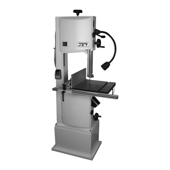
- Page 1 This .pdf document is bookmarked Operating Instructions and Parts Manual 14-inch Woodworking Band Saw Model JWBS-14SFX Shown with optional lamp kit #714403 427 New Sanford Road LaVergne, Tennessee 37086 Part No. M-714401 Ph.: 800-274-6848 Edition 1 01/2018 www.jettools.com Copyright © 2018 JET...
-
Page 2: Important Safety Instructions
Do not use this band saw for other than its and other substances known to the State of intended use. If used for other purposes, JET California to cause cancer. Avoid inhaling dust disclaims any real or implied warranty and holds... - Page 3 29. Check damaged parts. Before further use of 38. Turn off machine before cleaning. Use a brush machine, a guard or other part that is damaged or compressed air to remove chips or debris — should be carefully checked to determine that it not your hands.
-
Page 4: Table Of Contents
11.0 Blade Selection Guide ..........................21 12.0 Troubleshooting JWBS-14SFX Band Saw ....................22 12.1 Operational problems ..........................22 12.2 Mechanical and electrical problems ....................... 24 13.0 Replacement Parts ............................. 24 13.1.1 JWBS-14SFX (#714401) – Band Saw Assembly – Exploded View ........... 25... -
Page 5: About This Manual
Additional knowledge can be obtained from experienced users or trade articles. Whatever accepted methods are used, always make personal safety a priority. If there are questions or comments, please contact your local supplier or JET. JET can also be reached at our web site: www.jettools.com. -
Page 6: Specifications
4.0 Specifications Table 1 Model number JWBS-14SFX Stock numbers Band Saw with Stand 714400K Band Saw only 714401 Stand only 714402 Light kit (optional accessory) 714403 Motor and electricals Motor type Totally-enclosed fan-cooled induction, capacitor run Horsepower 1.75 HP (1.3 kW) -
Page 7: Base Hole Centers
L = length, W = width, H = height, D = depth The specifications in this manual were current at time of publication, but because of our policy of continuous improvement, JET reserves the right to change specifications at any time and without prior notice, without incurring obligations. -
Page 8: Setup And Assembly
Read and understand the entire contents of this manual before attempting assembly or operation. Failure to comply may cause serious injury. 5.0 Setup and assembly 5.1 Shipping contents See Figures 5-1 and 5-2. Figure 5-2: hardware package Box #1: Stand (not shown) 5.2 Tools required for assembly Box #2: Band saw (not shown) -
Page 9: Installing Dust Chute
5.6 Installing dust chute Mount dust chute (D, Figure 5-3) with four screws (HP4). Figure 5-4: table and guide rail installation Line up table to trunnion slots and insert screws and washers (HP3/5, Figure 5-5). Only hand tighten screws at this time. Figure 5-3 5.7 Installing and aligning table Refer to Figures 5-4 through 5-6. -
Page 10: Installing Guide Rail And Fence
Use a gauge (Figure 5-6) to carefully measure distance from miter slot edge to straight edge. Take measurements at both front and back of table – these should be identical. If miter slot is not parallel to blade, bump table with rubber mallet in the needed direction. -
Page 11: Storage Screw
Improper connection of the equipment-grounding conductor can result in a risk of electric shock. The conductor with insulation having an outer surface that is green with or without yellow stripes is the equipment-grounding conductor. repair replacement of the electric cord or plug is necessary, do not connect the equipment-grounding conductor to a live terminal. -
Page 12: Voltage Conversion
Zero setting of cursor cannot be used with horizontal fence position. Figure 6-1 6.2 Voltage conversion To convert the JWBS-14SFX from 115V to 230V, single phase operation: Switch the lead wires inside motor junction box, according to diagram found inside junction box cover. -
Page 13: Installing/Changing Blades
Open upper and lower doors by rotating door knobs. Remove dust block (C, Figure 7-4). Carefully remove blade from top wheel, then from between upper and lower blade guides and lower wheel. Slide blade out through slot in table. Guide new blade through table slot. Place blade loosely in upper and lower blade guides. -
Page 14: Blade Tracking
Keep in mind that too little or too much blade tension Rotate wheel by hand, observing position of can cause blade breakage and/or poor cutting blade through tracking window. The blade performance. should ride approximately at center of tire (Figure 7-7). Tip: When the band saw is not being used, raise tension lever to release position –... -
Page 15: Upper Thrust Bearing
7.9 Upper thrust bearing Blade teeth are sharp; use care when working near saw blade. Refer to Figure 7-8. The thrust bearing prevents backward deflection of blade during cutting. Disconnect band saw from power source. Loosen screws (M, Figure 7-8) with 3mm hex wrench and raise guard plate to expose thrust Figure 7-8: blade guide adjustment bearing. -
Page 16: Guide Post
7.12 Drive belt adjustments The drive belt and pulleys are properly adjusted by the manufacturer. However, belt tension should be occasionally checked when the band saw is new, as a new belt may stretch slightly during the breaking- in process. 7.12.1 Drive belt tension Check tension by pushing with moderate pressure on belt halfway between pulleys. -
Page 17: Operating Controls
gauge for a crosscut, the fence should be 8.0 Operating controls moved safely out of the way. Turn on band saw and allow a few seconds for 8.1 Start/stop switch the machine to reach full speed. Press green button to start. Press red paddle button to stop. -
Page 18: Crosscutting
9.3 Crosscutting When resawing thin stock, use a push block, push stick, or similar device to keep your hands away Crosscutting is cutting across the grain of the from the blade. workpiece, while using the miter gauge to feed the workpiece into the blade. -
Page 19: Width
9.7 Width 9.10 Set Band saw blades come in different standard widths, The term "set" refers to the way in which the saw measured from the back of the blade to the tip of the teeth are bent or positioned. Set patterns are usually tooth. -
Page 20: User-Maintenance
Clean band saw regularly to remove any resinous appropriate capacity. (See our website for a full line deposits and sawdust. of JET dust collectors.) Keep miter slot and guide bearings clean and free Periodically vacuum out the motor fan cover. -
Page 21: Blade Selection Guide
11.0 Blade Selection Guide Table 3 Identify the material and thickness of your workpiece. The chart will show the recommended PITCH, blade TYPE, and FEED RATE. Key: H – Hook L – Low S – Skip M – Medium R – Regular H –... -
Page 22: Troubleshooting Jwbs-14Sfx Band Saw
12.0 Troubleshooting JWBS-14SFX Band Saw 12.1 Operational problems Table 4 Symptom Probable Cause Correction Table tilt does not hold Lock handle not tight. Tighten lock handle. position under load. Trunnion locking mechanism is broken Replace trunnion locking mechanism. or worn. - Page 23 Symptom Probable Cause Correction Blade breaks Feed force too great. Reduce feed force. prematurely. Blade pitch too coarse. Refer to blade selection chart; use finer pitch blade. Guide bearings not properly supporting Check guide bearings for correct blade. position and signs of wear. Adjust or replace as needed.
-
Page 24: Mechanical And Electrical Problems
Non-proprietary parts, such as fasteners, can be found at local hardware stores, or may be ordered from JET. Some parts are shown for reference only, and may not be available individually. -
Page 25: Jwbs-14Sfx (#714401) - Band Saw Assembly - Exploded View
13.1.1 JWBS-14SFX (#714401) – Band Saw Assembly – Exploded View... -
Page 26: Jwbs-14Sfx (#714401) - Table And Miter Gauge Assembly - Exploded View
13.1.2 JWBS-14SFX (#714401) – Table and Miter Gauge Assembly – Exploded View... -
Page 27: Jwbs-14Sfx (#714402) - Band Saw Stand Assembly - Exploded View
13.1.3 JWBS-14SFX (#714402) – Band Saw Stand Assembly – Exploded View 13.1.4 JWBS-14LIT (#714403) – Band Saw Light Kit * – Exploded View * Optional Accessory – see your dealer to order. -
Page 28: Jwbs-14Sfx Band Saw (#714401) - Parts List
024 .... JWBS14SFX-024 ..Power Cord .............. 14AWGx3C, 5-15 plug .. 1 025 .... JWBS14SFX-025 ..Handwheel ..................... 1 026 .... JET-138R900 .... Jet Logo with Adhesive ..........5-7/16” x 2-1/4” ..... 1 027 .... JWBS14SFX-027 ..Wood Insert ............. 70x113x7.5 mm .... 1 028 .... - Page 29 Index No Part No Description Size 048 .... TS-2244162 ....Socket Head Button Screw ........M4x16 ......2 049 .... TS-2361081 ....Lock Washer ............8mm ......9 050 .... TS-2361061 ....Lock Washer ............6mm ......4 051 .... TS-2361101 ....Lock Washer ............10mm ......3 052 ....
- Page 30 Index No Part No Description Size 104 .... JWBS14SFX-104 ..Push Stick, Red ..................... 1 105 .... VB-A880 ....V-Belt ............... A-880 ......1 106 .... TS-154010 ....Hex Nut ..............M16 ....... 1 107 .... TS-1540081 ....Hex Nut ..............M12 ....... 3 108 ....
- Page 31 Index No Part No Description Size 163 .... F009884 ....Socket Head Button Screw ........M5x8 ......14 164 .... TS-2246082 ....Socket Head Button Screw ........M6x8 ......4 165 .... JWBS14SFX-165 ..Adjustable Handle ..................1 166 .... JWBS14SFX-166 ..Pointer ......................1 167 ....
-
Page 32: Jwbs-14Sfx Stand (#714402) - Parts List
....TS-152706 ....Hex wrench (not shown) .......... 5mm ......1 ....TS-152707 ....Hex wrench (not shown) .......... 6mm ......1 ....LM000332 ....Quick Release Label, JWBS-14SFX (not shown) ......... 1 13.1.6 JWBS-14SFX Stand (#714402) – Parts List... -
Page 33: Electrical Connections
14.0 Electrical Connections 14.1 Electrical Connections for 1.75HP, 1PH, 115V only (model #714400) 14.2 Electrical Connections for 1.75HP, 1PH, 230V only (model #714400) -
Page 34: Warranty And Service
Accessories; Shop Tools; Warehouse & Dock products; Hand Tools; Air Tools NOTE: JET is a division of JPW Industries, Inc. References in this document to JET also apply to JPW Industries, Inc., or any of its successors in interest to the JET brand. - Page 36 427 New Sanford Road LaVergne, Tennessee 37086 Phone: 800-274-6848 www.jettools.com...
Need help?
Do you have a question about the JWBS-14SFX and is the answer not in the manual?
Questions and answers