JVC KD-AV7010 Service Manual
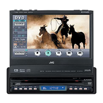
Dvd receiver with monitor
Hide thumbs
Also See for KD-AV7010:
- Installation & connection manual (6 pages) ,
- Instructions manual (255 pages) ,
- Service manual (141 pages)
Advertisement
Quick Links
SERVICE MANUAL
DVD RECEIVER WITH MONITOR
4
2005
MA184
1
PRECAUTIONS . . . . . . . . . . . . . . . . . . . . . . . . . . . . . . . . . . . . . . . . . . . . . . . . . . . . . . . . . . . . . . . . . . . . . . . 1-4
2
SPECIFIC SERVICE INSTRUCTIONS . . . . . . . . . . . . . . . . . . . . . . . . . . . . . . . . . . . . . . . . . . . . . . . . . . . . . . 1-7
3
DISASSEMBLY . . . . . . . . . . . . . . . . . . . . . . . . . . . . . . . . . . . . . . . . . . . . . . . . . . . . . . . . . . . . . . . . . . . . . . . 1-8
4
ADJUSTMENT . . . . . . . . . . . . . . . . . . . . . . . . . . . . . . . . . . . . . . . . . . . . . . . . . . . . . . . . . . . . . . . . . . . . . . . 1-35
5
TROUBLESHOOTING . . . . . . . . . . . . . . . . . . . . . . . . . . . . . . . . . . . . . . . . . . . . . . . . . . . . . . . . . . . . . . . . . 1-48
KD-AV7010
ATT
ASPECT
MENU
OK
GUI
SET UP
DISC
TUNER
1
2
4
5
7
8
10
11 / 0
VOLUME
TABLE OF CONTENTS
COPYRIGHT © 2005 Victor Company of Japan, Limited
MAIN
SUB
ZOOM
DUAL
AVOUT VOL
TOPMENU
RETURN
AV
3
6
9
12 /+1 0
Area suffix
J ------------- Northern America
No.MA184
2005/4
Advertisement

Related Manuals for JVC KD-AV7010


Summary of Contents for JVC KD-AV7010
-
Page 1: Table Of Contents
TROUBLESHOOTING ..............1-48 COPYRIGHT © 2005 Victor Company of Japan, Limited KD-AV7010 MAIN... - Page 2 Main unit Power Output Front and Rear Center Signal to Noise Ratio Load Impedance Equalizer Control Range Frequencies Level Frequency Response Frequency Range FM Tuner Usable Sensitivity 50 dB Quieting Sensitivity Alternate Channel Selectivity (400 kHz) 65 dB Frequency Response Stereo Separation Capture Ratio AM Tuner...
- Page 3 Screen Size Number of Pixel Drive Method Color System Aspect Ratio Allowable Storage Temperature Allowable Operating Temperature Dimensions (W Mass Power Requirement Operating Voltage Grounding System Allowable Operating Temperature Other Terminal Dimensions (W Installation Size Panel Size Mass Hideaway unit Input Terminals AV INPUT 1/2 Audio: 0.5 Vrms (Left/Right) Output Terminals (Level/Impedance) AV OUTPUT Audio: 2.0 V/20 k...
-
Page 4: Precautions
Safety Precautions Burrs formed during molding may be left over on some parts of the chassis. Therefore, pay attention to such burrs in the case of preforming repair of this system. Please use enough caution not to see the beam directly or touch it in case of an adjustment or operation check. - Page 5 Preventing static electricity Electrostatic discharge (ESD), which occurs when static electricity stored in the body, fabric, etc. is discharged, can destroy the laser diode in the traverse unit (optical pickup). Take care to prevent this when performing repairs. 1.2.1 Grounding to prevent damage by static electricity Static electricity in the work area can destroy the optical pickup (laser diode) in devices such as CD players.
- Page 6 Important for laser products 1.CLASS 1 LASER PRODUCT 2.DANGER : Invisible laser radiation when open and inter lock failed or defeated. Avoid direct exposure to beam. 3.CAUTION : There are no serviceable parts inside the Laser Unit. Do not disassemble the Laser Unit. Replace the complete Laser Unit if it malfunctions.
-
Page 7: Specific Service Instructions
SECTION 2 SPECIFIC SERVICE INSTRUCTIONS This service manual does not describe SPECIFIC SERVICE INSTRUCTIONS. (No.MA184)1-7... -
Page 8: Disassembly
SECTION 3 DISASSEMBLY Receiver unit section 3.1.1 Removing the detach panel assembly (See Fig.1) From the front side of the main body, slide the detach button in the direction of the arrow and remove the detach panel assem- Detach button bly. - Page 9 3.1.2 Removing the front panel assembly (See Fig.2 to 4) • Remove the detach panel assembly as required. (1) From the both sides of the main body, remove the two screw A attaching the front panel assembly. (See Figs.2 and 3) (2) From the bottom side of the main body, remove the FPC cover.
- Page 10 3.1.3 Removing the top drive unit (See Figs.5 to 8) • Prior to performing the following procedures, remove the de- tach panel assembly and front panel assembly. (1) From the both sides of the main body, remove the four screws B attaching the top drive unit. (See Figs.5 and 6.) (2) From the rear side of the main body, remove the three screws C attaching the top drive unit.
- Page 11 3.1.4 Removing the rear bracket (See Figs.9) • Prior to performing the following procedures, remove the de- tach panel assembly, front panel assembly and top drive unit. From the rear side of the main body, remove the five screws G attaching the rear bracket.
- Page 12 3.1.6 Removing the main board (See Figs.12 and 13) • Prior to performing the following procedures, remove the de- tach panel assembly, front panel assembly, top drive unit and DVD mechanism assembly. (1) From the rear side of the main body, remove the four screws K attaching the rear bracket.
- Page 13 Top drive unit section • Remove the top drive unit from the main body. (See "3.1.4 Removing the top drive unit".) 3.2.1 Removing the display drive unit (See Fig.1) (1) From the both sides of the top drive unit, remove the two screws A attaching the display guides L/R and remove the display guides L/R from the top chassis assembly.
- Page 14 3.2.2 Removing the drive gears and forth gear (See Figs.2 to 4) • Remove the display drive unit. (1) From the both sides of the display drive unit, remove the four screws B attaching the guide rails (L)/(R). (See Figs.2 and 3.) (2) From the top side of the display drive unit, pull the drive gears out of a drive gear shaft in the direction of the arrow...
- Page 15 3.2.3 Removing the cover (See Fig.5) • Remove the display drive unit. From the top side of the display drive unit, remove the two screws C attaching the cover. Cover Display drive unit Fig.5 (No.MA184)1-15...
- Page 16 3.2.4 Removing the third gear, worm gear and double worm (See Figs.6 to 11) • Remove the display drive unit and cover. (1) Remove the wire sheet with the wire from the motor. (See Fig.6.) Reference: Disconnect the wire from the connector motor board as required.
- Page 17 Motor bracket (S) Fig.9 Motor Worm gear 16 ± 0.1 (mm) Fig.10 Display drive unit Double worm Fig.11 (No.MA184)1-17...
- Page 18 3.2.5 Removing the worm gear, motor bracket (A) and third worm (See Figs.12 to 16) • Remove the display drive unit and cover. (1) Disconnect the wire from the connector tor board. (See Fig.12.) (2) Remove the screw F attaching the motor bracket (A). (See Fig.12.) (3) Take out the motor bracket (A), worm guide and motor to- gether.
- Page 19 3.2.6 Removing the second wheel and R.L.S. gear (See Figs.17 to 24) • Remove the display drive unit and cover. (1) Disconnect the wire from the connector tor board. (See Fig.17.) (2) Remove the screw J attaching the motor bracket (A). (See Fig.17.) (3) Take out the motor bracket (A), worm guide and motor to- gether.
- Page 20 Joint gear Second wheel Fig.20 Hex gear Second wheel Fig.21 Display drive unit Motor board CN331 Fig.22 1-20 (No.MA184) R.L.S. spring Hex gear R.L.S. bracket Third gear R.L.S. bracket Torsion spring (R.L.S.) R.L.S. spring R.L.S. bracket Fig.23 Torsion spring (R.L.S.) R.L.S.
- Page 21 Display unit section • Remove the display unit from the main body. (See "3.1.1 Removing the display unit".) 3.3.1 Removing the display back panel (See Figs.1 to 3) (1) From the both sides of the display unit, remove the six screws A attaching the display back panel.
- Page 22 3.3.2 Removing the switch board (See Fig.4) • Removing the switch board (See Fig.4) (1) Release the lock of the connector board in the direction of the arrow and disconnect the card wire. Reference: After connecting the card wire, fix it with the spacer(H) as before.
- Page 23 DVD mechanism assembly section 3.4.1 Removing the front end board (See Fig.1) Caution: Before disconnecting the flexible wire extending from the DVD pickup, solder the short-circuit point on the flexible wire using a grounding soldering iron. If you do not follow this instruction, the DVD pickup may be damaged.
- Page 24 3.4.2 Removing the top cover (See Fig.2) (1) Remove the two screws C attaching the top cover on the back of the body. (2) Remove the top cover upward. Reference: When reassembling, set part b of the top cover under the bending part c of the chassis frame.
- Page 25 3.4.4 Removing the clamper unit (See Figs.5 to 7) • Remove the top cover and the mechanism section. (1) Remove the clamper2 spring on the bottom of the mecha- nism section. (See Figs.5.and 6.) (2) Release the part d of the clamper spring from the bending part of the chassis base assembly.
- Page 26 3.4.5 Reattaching the clamper unit (See Figs.5 to 9) (1) Attach the clamper spring to the clamper unit. (See Fig.8.) (2) Move the clamper unit to set the side joints e and f to each boss of the chassis base assembly. Make sure that part g is inserted to the notch of the chassis base assembly.
- Page 27 3.4.6 Removing the front unit (See Figs.10 to 12) • Remove the top cover and the mechanism section. (1) Disconnect the flexible wire from connector front end board at the bottom of the body. (See Fig.10.) (2) Remove the screw E attaching the front unit on the top of the body.
- Page 28 3.4.7 Removing the loading arm assembly. (See Figs.13 and 14) • Remove the top cover, the mechanism section and the front unit. (1) From the top of the body, move the loading arm assembly. from the front side upward, and release the bosses from the right and left joints k and m of the chassis base assem- bly.
- Page 29 3.4.8 Removing the rod (L)(R)/roller assembly (See Figs.15 and 16) • Remove the top cover, the mechanism section, the front unit and the loading arm assembly. (1) Release the rod (L) and (R) from the joints q at the bottom of the loading arm assembly.
- Page 30 3.4.9 Removing the DVD pickup (See Figs.17 to 19) • Remove the front end board. (1) From the bottom of the body, turn the feed gear in the di- rection of the arrow to move the DVD pickup outwards. (See Fig.17.) (2) Remove the screw G attaching the thrust spring.
- Page 31 3.4.10 Removing the spindle motor (See Fig.20) • Remove the front end board. Remove the two screws J attaching the spindle motor on the bottom of the body. Caution: Perform adjustment when reattaching the spindle motor. DVD mechanism assembly Spindle motor Fig.20 (No.MA184)1-31...
- Page 32 3.4.11 Removing the feed motor assembly (See Figs.21 and 22) • Remove the front end board. (1) Remove the feed TRI. spring on the bottom of the body. (See Fig.21.) (2) Remove the two screws K attaching the feed motor assem- bly.
- Page 33 Hideaway unit section 3.5.1 Removing the top chassis (See Figs.11 to 3) (1) From the both sides of the main body, remove the four screws A attaching the top chassis. (See Fig.1 and 2.) (2) From the front side of the main body, remove the three screws A, screw B and four screws C attaching the top chassis.
- Page 34 3.5.3 Removing the hideaway board (See Figs.5 and 6) • Prior to performing the following procedures, remove the top chassis and DSP board. (1) From the rear side of the main body, remove the four screws E attaching the hideaway board. (See Fig.5.) (2) From the top side of the main body, disconnect the wire from the connector CN601...
-
Page 35: Adjustment
Adjustment method 4.1.1 Test instruments required for adjustment (1) Digital oscilloscope (100MHz) (2) Jitter meter (3) Digital tester (4) Digital multi meter (For voltage measurement) (5) Electric voltmeter (6) Frequency counter (7) Tracking offset meter (8) Test Disc : VT501 or VT502 (9) Extension studs : STDV001-3P (10) Extension cable : EXTAV70X-50PF 4.1.3 Connection method... - Page 36 4.1.4 Connecting diagram of extension cable Extension cable EXTAV70X-50PF 1-36 (No.MA184) Fix it with tape. Fix it in a slit. Fig.1 Fix it with tape. Monitor stability base Example : Wood panel (200mm x 170mm x 15mm) Extension stud STDV001-3P...
- Page 37 4.1.5 Adjustment method for jitter After replacing the pickup, set the unit in the service mode to display a jitter value on the LCD. Confirm that the jitter value measured with a jitter meter is within 12.0% of the jitter value displayed on the LCD. If it is within 12.0%, then adjustment is not necessary. If the measured jitter value is outside the 12.0% tolerance range, perform the following adjustments.
- Page 38 4.1.6 Jitter value conversion table Load the test disc and set the unit to the service mode. A jitter value converted to the hex value is displayed on the LCD. Refer to the corresponding decimal notation value shown in the following Jitter Conversion Table. The adjustment is OK if the jitter value measured with a jitter meter is within 12.0% of the jitter value displayed on the LCD.
- Page 39 4.1.7 Monitor adjustment Procedure: (1) Install a monitor to the main unit in the state that took off a display back panel. (2) Switch on the main unit. (3) According to the following chart, perform each adjustment. Item Free Run Frequency adjustment Touch Panel Sensor adjustment Touch Panel Sensor adjustment Touch Panel Sensor adjustment...
- Page 40 Service mode 4.2.1 Jigs and test instruments (1) Test disc: VT-501, VT-502 (2) NTSC signal generator (E version only) 4.2.2 Standard input/output conditions Power supply voltage: C14.4V (11V to 16V) Load impedance: (2 Speakers connection) Line output: 4.2.3 Service mode setting procedure (The DVD does not need to be loaded before starting the following procedure.) POWER/ATT 1.
- Page 41 4.2.4 Service mode menu MENU Service Mode Menu MONITOR TOUCH PANEL TEST TOUCH PANEL CALIBRATION AREA / REGION VERSION RUNNING MODE CHECK MODE EXPERT MODE [NEXT] : UP [PREV] : DW [MODE] : ENT This menu scrolls it with the [NEXT ]/[PREVIOUS ] buttons.
- Page 42 READ ERROR : Indication of an error history LOADING/EJECT mechanism error Monitor mechanism error Changer error CLEAR ERROR : Clear error history INITIALIZE : Initialize user set data INITIALIZE ALL : Initialize all data to the factory setting MEMORY CHECK : Check indication is done with a normal screen. MONITOR : Monitor service mode MONITOR MECHA CHECK : Check mode of a monitor mechanism DEMO SET UP : Change of a demonstration mode is done.
- Page 43 Touch Panel Calibration : Touch panel proofreading mode See "4.2.8 Touch panel manual operation proofreading procedure" for details. Push After the proofreading end, push the [PREVIOUS off the panel. An effective key in a proofreading mode [NEXT [PREVIOUS [POWER/ATT] 4.2.5 DVD unit check mode NORMAL PLAY TRACKING IN TRACKING...
- Page 44 4.2.6 Error code table (1) Error code table of LOADING/EJECT mechanism error Error code (1 byte) First byte [01] Eject error [09] Loading error Route No. (EJECT route No.) 1(2) 1(2) 2(2) 2(2) 2(2) 2(2) 3(1) 3(1) Route No. (EJECT route No.) 1(2) 1(2) 2(2)
- Page 45 (2) Error code table of monitor mechanism error Error code (1 byte) First byte [01] CLOSE error [09] OPEN error [0A] SLIDE error (3) Error code table of changer Outbreak condition Tray extension Tray-in switch time out error (Tray-in switch Low,Tray-out switch High) Tray-out switch time out (Tray-in switch High,Tray-out switch High) Tray-in switch time out...
- Page 46 4.2.7 Monitor adjustment 1. Switch on the main unit and insert a test disc (VT-501 or VT-502). Play a 3TR(100% color bar) of the test disc and pause it. 2. In a state of procedure 1, set the main unit in a service mode. (See "5.1.3 Service mode setting procedure".) 3.
- Page 47 4.2.8 Touch panel manual operation proofreading procedure Procedure 1 Proofreading (1) Set the main unit in a touch panel proofreading mode. (2) Push the center of the figure of a cross in a circle of green (81h to 89h) on the panel in turn. a) Push for each 3 points of the upper part of 81h and 82h and 83h with a thumb of the right hand (or, left hand) on the panel from a direction.
-
Page 48: Troubleshooting
AV bus cable between main unit and hideaway unit RESET P-ON HPAL SPDIF DVDAR-GND DVDAL-GND 1-48 (No.MA184) SECTION 5 TROUBLESHOOTING QAM0612-002 6000 mm QAM0612-001 2500 mm Black HPA-GND White SPDIFGND Light green Brown DVDAR DVDAL Yellow Blue HPAR Natural VIDEO-OUT VIDEO-GND Orange VIDEO-IN... - Page 49 Center speaker / rear camera cord VI/WH BK/WH 1 VI/WH 3 BK 4 BK/WH Extention aerial cord PLUG BLACK VIOLET 2500 mm 2593 mm WHITE BACK CAMERA CENTER JACK (No.MA184)1-49...
- Page 50 Power cord for main unit 4 BK 1 YL 2 RD 5 OR CORE EARTH 1-50 (No.MA184) Black Orange EARTH Earth CORE POWER LEAD/ MEMORY BACK UP POWER LEAD GROUND ILLUMINATION CONTROL MJ-164A Yellow Core...
- Page 51 Power cord for hideway unit 9 WH 8 GN GN/BK WH/BK GY/BK VI/WH 12 GY 5 VI 13 NC 4 BL 14 L.GN BL/WH 15 NC 2 NC 1 BK 16 YL 1000 mm 1 BK GROUND 3 BL/WH 4 BL 5 VI 6 VI/BK 7 GN/BK...
- Page 52 Victor Company of Japan, Limited AV & MULTIMEDIA COMPANY CAR ELECTRONICS CATEGORY 10-1,1chome,Ohwatari-machi,Maebashi-city,371-8543,Japan (No.MA184) Printed in Japan...