Table of Contents
Advertisement
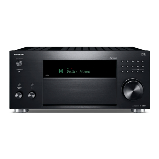
11.2ch AV Receiver
TX-RZ830
Final Issue
Final Issue
Service Manual
THIS MANUAL IS APPLICABLE TO THE FOLLOWING MODEL(S) AND TYPE(S).
Model
Color
Type
TX-RZ830
(B) – Black
MDC
TX-RZ830
(B) – Black
MMP
TX-RZ830
(S) - Silver
MMP
TX-RZ830
(B) – Black
MMB
TX-RZ830
(B) – Black
MMR
TX-RZ830
(B) – Black
MMA
Published by Onkyo & Pioneer Corporation Global CS Department 2018
Power Requirement
Remarks
AC 120 V
Canada/USA/(Mexico)
AC 220 V to 240 V
Europe
AC 220 V to 240 V
Europe
AC 220 V to 240 V
UK
AC 220 V to 240 V
China
AC 220 V to 240 V
Australia/New Zealand
For details, refer to "Important Check Points for good servicing".
Ref.No. : 4799
Advertisement
Table of Contents

Related Manuals for Onkyo TX-RZ830


Summary of Contents for Onkyo TX-RZ830
- Page 1 (B) – Black AC 220 V to 240 V China TX-RZ830 (B) – Black AC 220 V to 240 V Australia/New Zealand For details, refer to "Important Check Points for good servicing". Published by Onkyo & Pioneer Corporation Global CS Department 2018...
-
Page 2: Service Notes
Important Check Points for Good Servicing Service Notes In this manual, procedures that must be performed during repairs are marked with the below symbol. Please be sure to confirm and follow these procedures. 1. Product safety Please conform to product regulations (such as safety and radiation regulations), and maintain a safe servicing environment by following the safety instructions described in this manual. Use specified parts for repair. -
Page 3: Other Cautions
“!” in the parts list are critical for risk of fire and electrical shock. Replace these components with ONKYO parts whose part numbers appear as shown in this manual. 2. Safety check after servicing (1) To ensure safety, check that the covered insulating sheet or tube are removed, all parts and wires which are removed or disconnected while servicing have been put back to their original positions after servicing. -
Page 4: Note For Parts List
File Name of Parts List File (EXCEL File) Note for Parts List When parts list is EXCEL file, please refer to the following explanation about file name. P L _ T X – S R 3 4 3 ( B ) M J J . x l s x Look at the rear panel serial number 6 digit. -
Page 5: Front Panel
4. Indoor FM antenna (1) 5. AM loop antenna (1) 6. Power cord (1) Dimensions (W × H × D) : 435 mm × 201.5 mm × 398 mm (17-1/8" × 7-15/16" × 15-11/16") Weight : 14 kg (30.9 lbs.) TX-RZ830... - Page 6 Reset Reset 【STORE】 [ SETUP ] + [ ENTER ] x 2 【RESET】 1. [ CBL/SAT ] + [ STANDBY ] 2. Unplug the power cord from AVR after the disappeared "Clear" of FL tube and AVR goes standby. 【RECALL】 [ SETUP ] + [ RETURN ] x 2 Detail Key Operation is here.
-
Page 7: Protect Mode
Protect Mode Diagnostic Function The unit goes into standby automatically when detect the abnormal condition of thermal detection, dc voltage detection or current detection. (e.g. TX-NR555 block diagram below) BAPRC PCB Info BAETC PCB Info THERMAL THERMAL DETECT Q6800 SPRLF Q7009 VOLH PON_MAIN... - Page 8 DRX-5.2 BACLA BATRM TX-NR585 BACLA-1988 TX-NR585 BATRM-2023 ↑ ↑ TX-NR686 TX-NR686 TX-NR787 BACLA-2559 TX-NR787 BATRM-2601 ↑ ↑ TX-RZ630 TX-RZ630 ↑ ↑ TX-RZ730 TX-RZ730 TX-RZ830 BACLA-2587 ↑ TX-RZ830 BACLA-2568 ↑ DRX-3.2 DRX-3.2 ↑ ↑ DRX-4.2 DRX-4.2 BACLA-2596 ↑ DRX-5.2 DRX-5.2 COMMON...
-
Page 9: Self-Diagnostics
Self-diagnostics Diagnostic Function This function is for avoiding the rupture of electrolytic capacitors with amplifier circuit failure during power-ON. Operation of Self-diagnostic Display of during Self-diagnostics Self-diagnostic will start at the timing of next power on, after goes to the protect mode 2 Line FL tube type by Current detection or DC voltage detection. - Page 10 Repair Process and How to Confirm Diagnostic Function Confirmation of the protect cause Protected by current detection While NG channel is displayed, You can confirm the protect cause by following the step below. 1. Press the Enter button 2. The protect cause are displayed for 5 seconds. Protected by DC Voltage detection Please check the around of those amplifier circuit and repair it.
- Page 11 Enter Service mode, Service Information Diagnostic Function How to change History No. 1 ~ 3. How to enter to service mode. [CURSOR LEFT] or [CURSOR RIGHT] Step1 : I 8 0 F 3 0 D D 01: 23 [DIMMER] + [ON/STANDBY] x 2 [CURSOR LEFT] [CURSOR RIGHT] [CUROR LEFT]...
-
Page 12: Service Information
Service Information Diagnostic Function Listening Mode Code List NORMAL_LMD_BEGIN SURR_LMD_BEGIN THX_MUSIC_LMD_BEGIN THX_CINEMA_LMD_BEGIN AUDYSSEY_LMD_BEGIN LAST SURR_20_PLII_MOVIE THX_20_PLII_MUSIC THX_20_PLII_MOVIE AUDYSSEY_20_PLII_MUSIC PURE SURR_20_PLII_MUSIC THX_20_PLIIX_MUSIC THX_20_PLIIX_MOVIE AUDYSSEY_20_PLIIX_MUSIC DIRECT SURR_20_PLII_GAME THX_20_PLIIZ_MUSIC THX_20_PLIIZ_CINEMA AUDYSSEY_20_NEO6_MUSIC STEREO SURR_20_PLIIX_MOVIE THX_20_NEO6_MUSIC THX_20_NEO6_MOVIE AUDYSSEY_20_NEURAL_CINEMA MONO SURR_20_PLIIX_MUSIC THX_20_NEURAL_MUSIC THX_20_NEURAL_CINEMA AUDYSSEY_20_NEURAL_MUSIC ORCHESTRA SURR_20_PLIIX_GAME THX_51_OFF_MUSIC THX_51_OFF_CINEMA AUDYSSEY_20_PLII_MOVIE... - Page 13 Wireless LAN 5GHz Setting WiFi 5GHz Setting IMPORTANT!! Service Parts information: Back Ground: The default country code is set on “Processing Circuit Board(PRC board)”. It is totally different from Radio Law at the each country on 5GHz band. You must make sure and set up the “Country Code“...
- Page 14 Wireless LAN 5GHz Setting WiFi 5GHz Setting Case5; IMPOTANT!! When you repair the “C” destination products and replace “C” destination PRC board Make sure and Setup Country Code and the customer live in US, it is no necessary to setup Country Code You have to make sure country code for using or replacing “Processing Circuit PC Because “C”...
- Page 15 Wireless LAN 5GHz Country Code 1/2 WiFi 5GHz Setting Region Country Code Region Country Code Region Country Code Japan Canada China Bahrain Mexico Hong Kong Kuwait Brazil Korea Oman Middle East Chile Taiwan Qatar Guatemala Singapore Lebanon Puerto Rico Malaysia Jordan Trinidad Philippines...
- Page 16 Wireless LAN 5GHz Country Code 2/2 WiFi 5GHz Setting Region Country Code Region Country Code Region Country Code Germany Cyprus Liechtenstein Estonia Monaco France Slovenia Montenegro Netherlands Bulgaria San Marino Italy Greece Vatican City Switzerland Romania Kosovo Denmark Lithuania Kaliningrad(Russia) Sweden Serbia Gibraltar(UK)
- Page 17 How to read PRC Board part number and Default value of Country Code WiFi 5GHz Setting 1B5142049-2A686MDC Board No. Suffix No. Destination Model Number Last 3 Digit 585 : TX-NR585 PRC Board Default setting Country Code Code Main Country 686 : TX-NR686 North America 787 : TX-NR787 United State...
- Page 18 Step2 : [TONE +1] ( Rotate “TONE” knob right 1 click) Download the firmware file (package file) from the Onkyo FTP-server. However European NET Firmware Version will appear on the main unit’s display. service partners should download the firmware file (package file) from the ExtraNet.
- Page 19 How to Update (service mode) 1/2 Firmware Overwriting is also possible. USB -> ALL: ALL firmware update ( default ) USB -> DSP1: DSP firmware update Connect the USB strage to the USB port on the unit. USB -> OSD: OSD firmware update USB ->...
- Page 20 How to Update (service mode) 2/2 Firmware 4. Press [ENTER] button. Start update firmware. Press [ON/STANDBY] button, and the unit turns on. Check the new FW version number. <Note> If the procedure might not be successful, please select “USB -> ALL”. Wait until update is completed.
- Page 21 TX-RZ730 R Z 7 3 0 0 5 5 0 TX-NR787 N R 7 8 7 0 3 0 0 TX-RZ830 R Z 8 3 0 0 6 0 0 TX-RZ830 R Z 8 3 0 0 6 1 0...
- Page 22 How to Check Idling Current Check Idling Current a. Idling Pre-check Channel FL,FR,C,SL,SR,H1L,H1R,H2L,H2R Terminals P6021,P6022,P6023,P6025,P6026,P6027,P6028 (BAAF-2597), P6029,P6030 (BAAMP-2600) *Connect 1/4W 100 ohms resisters in each probe of multi mater . *Make sure from 0.7mV to 21mV, When it is not this range, you have to make sure again repair. b.
- Page 23 Hookup and Setting No Sound ■ No sound from connected player □ Chose input selector which is assigned to connected input terminal ? □ Isn’t muting on ? ■ No sound from connected TV □ Chose wrong input selector ? □...
- Page 24 Hookup and Setting No Picture ■ In general □ Connection cable is bent , twisted or damaged ? □ Input is switched on TV ? ■ No picture from connected player by HDMI input terminal □ Chose input selector which is connected to player ? □...
- Page 25 Hookup and Setting No Power ■ In general □ Check if the connection cable is bent or twisted, damaged. ■ There is time when indication on the front panel doesn't just light up. □ Please check the connecting cord of a DISPLAY PCB. ■...
-
Page 26: Troubleshoot
BASW-2577 BADG-2586 Audio Signal (FL OUT) BADIS-2575 BAAF-2597 J4111(BAAF-2597) BAAF-2597 J4111 Audio Signal (FL OUT) BASW-2576 BACLA-2587 Q6001, Q6021(BAAF-2597) BACLA-2587 Base Audio Signal (FL OUT) BASW-2578 P2800B(BAPRC-2605) BATRM-2601 +3V (SPRLF, HIGH) P6021(BAAF-2597) BAAF-2597 P6021 Audio Signal (FL OUT) BATRM-2601 TX-RZ830... - Page 27 BADIS-2575 BAAF-2597 Q1501(BADG-2586) BADG-2586 Audio Signal (FL OUT) BASW-2576 BACLA-2587 J4111(BAAF-2597) BAAF-2597 J4111 Audio Signal (FL OUT) BASW-2578 Q6001, Q6021(BAAF-2597) BACLA-2587 Base Audio Signal (FL OUT) P2800B(BAPRC-2605) BATRM-2601 +3V (SPRLF, HIGH) P6021(BAAF-2597) BAAF-2597 P6021 Audio Signal (FL OUT) BATRM-2601 TX-RZ830...
- Page 28 BAAF-2597 BAPRC-2605 J4111 Audio Signal (FL OUT) BADG-2586 Q6001, Q6021(BAAF-2597) P7001 BACLA-2587 BATRM-2601 Base Audio Signal (FL OUT) P2800B(BAPRC-2605) BATRM-2601 BASW-2606 +3V (SPRLF, HIGH) P6021(BAAF-2597) BAPS-2585 BASW-2577 BAAF-2597 P6021 Audio Signal (FL OUT) BADIS-2575 BAAF-2597 BATRM-2601 BASW-2576 BACLA-2587 BASW-2578 TX-RZ830...
- Page 29 Of course, with actual repair there are also troubles due to damaged Power Transformer, Wiring, soldering etc. in addition to PCB assembly. No Good Process Check Point Damaged PCB P2802B(BAPRC-2605) BAPS-2585 +12V (+12VSTB) BAPRC-2605 BAPRC-2605 BADG-2586 P7001 BATRM-2601 BASW-2606 BAPS-2585 BASW-2577 BADIS-2575 BAAF-2597 BASW-2576 BACLA-2587 BASW-2578 TX-RZ830...
- Page 30 Of course, with actual repair there are also troubles due to damaged Power Transformer, Wiring, soldering etc. in addition to PCB assembly. No Good Process Check Point Damaged PCB P2802B(BAPRC-2605) BATRM-2601 +12V (+12VSTB) P2800B(BAPRC-2605) BAPRC-2605 P2800B(BAPRC-2605) BATRM-2601 Video Signal BAPRC-2605 BADG-2586 P7001 BAPRC-2605 BATRM-2601 BASW-2606 BAPS-2585 BASW-2577 BADIS-2575 BAAF-2597 BASW-2576 BACLA-2587 BASW-2578 TX-RZ830...
- Page 31 Of course, with actual repair there are also troubles due to damaged Power Transformer, Wiring, soldering etc. in addition to PCB assembly. No Good Process Check Point Damaged PCB P2802B(BAPRC-2605) BATRM-2601 +12V (+12VSTB) P2800B(BAPRC-2605) BAPRC-2605 P2800B(BAPRC-2605) BATRM-2601 Video Signal BAPRC-2605 BADG-2586 P7001 BAPRC-2605 BATRM-2601 BASW-2606 BAPS-2585 BASW-2577 BADIS-2575 BAAF-2597 BASW-2576 BACLA-2587 BASW-2578 TX-RZ830...
- Page 32 Check the damage in the red framework part as shown with visual inspection. BADIS-2575 BASW-2578 e.g. Broken, Burnout, Discoloration, etc. 1. When being not turned on with remote control unit only, BADIS-2575 is abnormal. 2. When being not turned on with button on the main unit only, BADIS-2575 is abnormal. TX-RZ830...
- Page 33 Audio Signal (FL-) Video Signal +3.3V +12V P2800B P7001A P7001 ● Check damage and connection How to check Front 1.Disconnect the FFC from the socket. 2.Check the contacts of the FFC. Back ●Each voltage is shown as the reference value. TX-RZ830...
- Page 34 R1585 R1601 R1641 Audio Signal (FL OUT) R1545 R1546 R1566 R1664 R1665 R1511 R1587 R1607 R1567 Q1921 R1547 R1663 R1662 R1667 R1666 R1926 R1568 R1548 C1928 R1657 R1861 R1927 R1821 Back ●Each voltage is shown as the reference value. TX-RZ830...
- Page 35 Check Point (BAAF-2597) Trouble Shoot F6901 F6902 P4301A J4111 +26V Audio Signal (FL OUT) P6021 Audio Signal (FL OUT) Back Q6021 Q6001 ●Each voltage is shown as the reference value. TX-RZ830 Audio Signal (FL OUT) (Base) (Base)
- Page 36 F 9 0 0 2 B F 9 0 1.SEC2_1 2.NC 3.SEC2_2 RL9001 Q9010 R9009 C9011 R9005 R9022 Q9032 Q9005 Q9033 R9004 R9018 D9004 1.+12VSTB 2.GNDDG 3.12VSTB 4.GNDDG 5.POFF2 6.PON_SMPS 7.MPON Back ●Each voltage is shown as the reference value. TX-RZ830...
- Page 37 C5622 C5623 R5823 R5821 C6423 C6422 C6421 R6302 R6301 J5012 J5010 R6303 C6302 R6403 J5011 R6401 P6002A P6001A P5509B C6303 J5001 R6402 J5000 e.g. Broken, Burnout, Discoloration, etc. P6003A BAAF-2597 Back ●Each voltage is shown as the reference value. TX-RZ830...
-
Page 38: How To Check
3.KEYINT0 2.FLAC2 2.KEY1 1.FLAC1 1.KEY0 Q7855 Q7851 J7939 P7001 ● Check damage and connection How to check P7001 1.Disconnect the FFC from the socket. 2.Check the contacts of the FFC. Back ●Each voltage is shown as the reference value. TX-RZ830... -
Page 39: Digital Audio
BLOCK DIAGRAM(Analog Audio) Schematic Diagrams Headphone Main L except Z8/D5/L5 Direct L Main R AUX_L Main +29dB Multi1 Multi3 Front L AUX_R DACFL DownMix Direct R AMUT MICOUT Main +29dB DACFR Multi1 Front R Multi3 SPRLF TUNER_L (Only T2-00) -6dB Main TUNER PACK DACSW... -
Page 40: Block Diagram Video
BLOCK DIAGRAM(Video) Schematic Diagrams BAPRC-2605 EMAC USB 2.0 SDIO/UART Q3001 AM3354 HDMI IN1 HDMI IN2 NET/OSD VIDEO Q8401 RGB565 D[3-7]=B[0-4]=LCD[0-4] HDMI Tranceiver D[3-23] D[10-15]=G[0-5]=LCD[5-10] PCLKIN 211 AM_LCD_PCLK HDMI IN3 MN864787 D[19-23]=R[0-4]=LCD[11-15] VSYNCIN 59 AM_LCD_VSYNC HSYNCIN 60 AM_LCD_HSYNC DEIN 61 AM_LCD_AC_BIAS_EN HDMI IN4 TMDS MAIN OUT... - Page 41 BLOCK DIAGRAM(Digital Audio) Schematic Diagrams BAPRC-2605 Wi-Fi/BT Module WCBN806L PCMCLK Q3651 PCMFR1 10 PCMOUT 12 Ethernet PHY PCMIN 14 KSZ8091RNL Except D4/D5 EMAC USB 2.0 SDIO/UART Q3404 Q1301 CS49844A-CQZ D808K013DPTP456 Q3001 AM3354 only Z8/D5/L5 ARC/eARC Receiver SiI9437 Q8400 MCLK 8 eARC_MCK SCK 10 eARC_BCK...
- Page 42 ASP SECTION Schematic Diagrams FROM BADG-2558(PART-9):TX-NR686,TX-RZ630,TX-NE787,TX-RZ730 FROM BADG-2586(PART-9):TX-RZ830 FROM BADG-2573(PART-9):VSX-LX303 FROM BADG-2567(PART-9):DRX-3.2,DRX-4.2 FROM BADG-2595(PART-9):DRX-5.2 BD TO BD BD TO BD 1 2 3 4 5 6 7 8 9 10 11 12 13 14 15 16 17 18 19 20 21 22...
-
Page 43: Amp Section
AMP SECTION Schematic Diagrams CRIMP AS CRIMP AS *P6903B *P6904B NSAS-2P2499 P6905 BAAF-2597(2/2) -69V AV=29dB AV=29dB R5505 +B1SBR 1/4W R5865 R5825 Q5385 1/4W INA6006AP1-T111 R6141 Q6001 R6145 Q6005 LIST LIST 0.22 0.22 D6601 D6605 R6601 1/4W DA2J10100 1/4W R6605 DA2J10100 C5025 IN_L J6441... - Page 44 THERMAL SENSOR SECTION Schematic Diagrams BAETC-2598 Q6800 LM61CIZ C6801 THERMAL C6800 (PTH) 104Z Q6800A Thermal connect +3.3VDC R6808 220k 1 2 3 4 5 P6800A CHD-1.5-5 FROM BAPRC-2387(PART-14) TX-NR787/RZ630/RZ730/RZ830,DRX-3.2/4.2/5.2...
- Page 45 R5509 VH TOP 250V Q6009A R25J-10 NPLG-2P149 IMSA-9201B-1-06Z388-PT1 1/4W 25055165 VH SIDE Functions Cir.No/Group TX-RZ630 DRX-3.2 VSX-LX303 TX-NR787 TX-RZ730 DRX-4.2 TX-RZ830 DRX-5.2 VSX-LX503 NPLG-2P158 Input Silver Gold Silver Gold Silver Gold Silver R5829 Terminal Color 25055174 回路番号末尾:* 9 25045845 25045812...
- Page 46 AMP SECTION Schematic Diagrams BACLA-2559-1 TX-NR787,TX-RZ630/730 BACLA-2568-1 DRX-3.2/4.2 BACLA-2574-1 VSX-LX303 BACLA-2587-1 TX-RZ830 BACLA-2596-1 DRX-5.2 BACLA-2620-1 VSX-LX503 CLASS A Destination table MODEL Q5382,Q5422 INA6006AP1-T111 R5502 T7/Z7 Z8/D4/D5/L5 R5822 T7/Z7/Z8 250V 1/4W R25J-2.2 /D4/D5/L5:Mount R25J-10 3.3kΩ R500* 1.5kΩ OtherModel:NM (Preout enabled Model)
- Page 47 TX-RZ730 AFIN D'ASSURER UNE PROTECTION PERMANENTE CONTRE LES RISQUES D'INCENDIE, EX) 030 -> 3pF, 330 -> 33pF, 331 -> 330pF, 333 -> 0.033uF TX-RZ830 REMPLACER UNIQUEMENT PAR UN FUSIBLE DE MEME TYPE ET CALIBRATION COMME INDIQUE. VSX-LX303 CIRCUIT IS SUBJECT TO CHANGE FOR IMPROVEMENT.
- Page 48 DRX-4.2 上 *R2105 3 12 4053INH +3.3VST (JAMICON) *C2115 Mount only R2108 A 11 CONA CONA Destination P2900B IRIN Integra D3/D4 TX-RZ830 B 10 CONB CONB 1D,1E,1F,1G,1H,1J,1K,1L, TRGC OR CE04W50V2.2M(VR) GND7 COMPONENT IN2 CONC CONC 1M,1N,1P,1Q,1R,1T,1W,1X, Mount TRGA_Z2 (394680227T) GND8 DRX-5.2...
-
Page 49: Destination List
Powerd Zone2 out SECTION Schematic Diagrams BATRM-2607 Destination List Destination Model * Only Z7/Z8MD*/Z8MM*/D4/D5/L5 TX-RZ730 DRX-4.2 TX-RZ830 *J6551~J6557:TA Wire Mout only Z7/Z8/D4/D5/L5 DRX-5.2 VSX-LX503 +26VRL *J6551 *Q6551 OR:DTC123JCAT116 *J6552 GNDRL (2219040R2) *D6551 *Q6551 *D6551 OR:1SS352(223234R2) KRC105S DA2J10100 *RL6551 *C6551 OR:NRL-2P5A-DC24-193(25065703) - Page 50 RS232C SECTION Schematic Diagrams BAETC-2602 Destination Model TX-RZ630 DRX-3.2 VSX-LX303 TX-NR787 RS-232C TX-RZ730 *C2900 DRX-4.2 103K TX-RZ830 DRX-5.2 VSX-LX503 J2900 TA WIRE *P2900A *R2900 CHD-1.5-3 GNDDG BATRM-2601 RS232RXD RS232TXD (PART-7) *R2901 P2900: 2009991282UL NSAS-3P2093 1.5mmPitch 100mm PHR-3 *P2900A *C2901 *P2901...
-
Page 51: Display Section
DISPLAY SECTION Schematic Diagrams BADIS-2554 DISPLAY Q7905A Q7905 (FL) 016MT096GINK FLAC1 FLAC2 P7550 FLAC1 R7801 FLAC2 R7900 RNU1/2WCJ-8.2 SEC3_1 Q7901 INC5001AP1-T111 P7800 D7900 R7903 L7900 Q7900 INA5001AP1-T111 or KTA1661-Y LBC2518T2R2M SEC3_2 J7900 AUXL RL1N4003 Q7903/7904 or 2SC2881-Y AUXR or 2SC2712-GR AUX_L R7914 MICOUT... - Page 52 DISPLAY(HEAD PHONE)SECTION Schematic Diagrams BAETC-2555 HEADPHONE C7884 102J P7881 GND_DG MSJ-064-05A SR HPDET R7881 RS1/2WBJ-330 HP_GND R7880 RS1/2WBJ-330 CHASSIS TX-NR787/RZ630/RZ730...
- Page 53 DISPLAY SECTION Schematic Diagrams BADIS-2560 DISPLAY Q7905A Q7905 (FL) 016MT096GINYK EH SIDE R7905 R7919 FLAC1 220 1/4W 1/4W P7900 R7900 C7907 C7915 NPLG-5P220 RNU1/2WCJ-8.2 250V 223K 223K SEC3_2 FLAC2 Q7900 TP61 D7900 INC5001AP1-T111 Q7901 L7900 R7903 INA5001AP1-T111 LBC2518T2R2M SEC3_1 FLAC2 Q7903/7904 J7900 RL1N4003...
- Page 54 SW SECTION Schematic Diagrams BASW-2561 Hybrid-Stby Q7750 SWITCH KRC105S R7750 D7750 HLMP-Y701 AMBER or DTC123JCAMGT116 (2219040R2) +3.3S LEDTHRU GNDDG KEY1_1 KEY0 KEY1_2 R7601 R7602 R7603 R7604 R7605 KEY0_1 R7618 3.9k DRX-3.2/4.2...
- Page 55 DISPLAY(HEADPHONE)SECTION Schematic Diagrams BAETC-2563 HEADPHONE C7884 102J P7881 GNDDG MSJ-064-05A GR R7881 HPDET RS1/2WBJ-330 1/2W GNDFL R7880 1/2W RS1/2WBJ-330 1 2 3 4 P7882 TER21-0130V DRX-3.2/4.2...
- Page 56 R7856 C7855 KRA102S or DTA114ECAT116 10u 16V 330J (2218980R2) P7851A: or NSCT-3P874(25051087) Q7850 -V -V NJM4580CG P7851: JL3 150 B(3J150606B15) P7590A: or NSCT-7P878(25051091) CHD-1.5-7 P7590: P7593B P7590A JL7 150 B(7J150606B15) NPLG-7P354 TO BASW-2576(Page 21/60) TO BASW-2606(Page 22/60) Selector DOOR TX-RZ830...
- Page 57 DISPLAY(SETUP)SECTION Schematic Diagrams BASW-2576 KEY2 R7621 R7622 R7623 R7624 R7625 R7626 R7627 R7628 R7629 1.2k 2.2k 3.9k DOOR GND_DG KEYINT1 KEY0_2 KEY0_3 KEY2 R7632 R7633 R7634 R7635 KEY3_1 GND_DG P7590B: or NSCT-7P878(25051091) S7601-7636 NPS-111-S681 or NPS-111-S677(25035714T) R7603 R7604 R7605 TX-RZ830...
- Page 58 Schematic Diagrams BASW-2606 or NSCT-7P878(25051091) KEY0_2 KEY0_3 xKEYINT1 KEY1 xKEYINT0 GND_DG S7601-7632 NPS-111-S681 or NPS-111-S677(25035714T) P7593:1.5mmpitch 100mm SocketAS R7606 R7607 R7608 R7609 NSAS-7P2125(2009991314UL) 1.2k 2.2k 3.9k GND_DG R7611 R7612 R7613 R7614 R7615 R7616 R7617 R7618 R7619 1.2k 3.9k 2.2k TX-RZ830...
- Page 59 DISPLAY(VOLUME)SECTION Schematic Diagrams BASW-2577 VOLUME P7592B: or NSCT-3P874(25051087) VOLA VOLB GND_DG S7770 XREB12504PVB30FINB1-2-24E/I w/o click TX-RZ830...
- Page 60 D7751 Q7751 KRC105S or DTC123JCAT116 +3.3VS (2219040R2) LMDB TONEB LEDPURE TONEA KEY3 LMDA KEY3_1 KEY0_1 KEY0 GND_DG R7631 R7601 TONE P7591B:or NSCT-12P883(25051095) LISTENING MODE S7740 S7774 S7601/7602/7631/7632 XREB125(9X11.5)PVB30FINB1-2-24 XREB125(9X11.5)PVB30FINB1-2-24 NPS-111-S681 or NPS-111-S677(25035714T) w/ click w/ click Chassis GND レジスト剥ぎ TX-RZ830...
- Page 61 DISPLAY(MIC)SECTION Schematic Diagrams BAETC-2580 L7850 MIC_DET LBC2518T2R2M GNDA P7850 MIC_IN R7859 MIC_IN MIC_DET_1 GNDA MSJ-035-12A-B-AG-PBT(OC257) L7851 or NSCT-3P874(25051087) LBC2518T2R2M CRIMP AS P8502A TX-RZ830...
- Page 62 DISPLAY(HEADPHONE)SECTION Schematic Diagrams BAETC-2581 HEADPHONE C7884 102J P7881 GND_DG MSJ-064-05A SR HPDET R7881 1/2W HP_GND R7880 Side type 1/2W 1 2 3 P7882 TP00370-21 TX-RZ830...
- Page 63 DISPLAY SECTION Schematic Diagrams BADIS-2588 DISPLAY Q7905A (FL) Q7905 016MT096GINYK FLAC1 FLAC1 GNDDG FLAC1 FLAC2 FLAC2 GNDDG 1/4W 1/4W R7910 R7914 Q7901 P7990A: INA5001AP1-T111 VP/VH or 2SC2712-GR or NSCT-5P876(25051089) (2213145R2) or 2SA1201-Y L7900 P7990: Q7903 or 2SC2712-GR(2213145R2) (2217554AR2) LBC2518T2R2M JL5 200 B(5J200606B15) KTC3875-GR Q7904 R7913...
- Page 64 DISPLAY(SWITCH)SECTION Schematic Diagrams BASW-2589 SWITCH J7762 J7761 FLAC1_1 or 2SC2881-Y FLAC2 R7761 (2217564AR2) SEC3_1 GND_DG D7762 Q7761 TP7761 RL1N4003 FLAC1 R7764 INC5001AP1-T111 SEC3_2 FLAC2 GND_DG D7763 D7761 RL1N4003 RL1N4003 P7990B: or NSCT-5P876(25051089) D7765 DZ2J180M0L Hybrid Standby(Yellow) or DTC123JCAT116 (2219040R2) Q7750 D7750 R7750 KRC105S...
-
Page 65: Master Volume
DISPLAY(VOLUME)SECTION Schematic Diagrams BASW-2590 MASTER VOLUME VOLB_1 VOLA_1 GND_DG S7770 XREB125(9X11.5)PVB30FINB1-2-24 DRX-5.2... - Page 66 DISPLAY(MIC,HEADPHONE)SECTION Schematic Diagrams BAETC-2592 L7850 MICIN_1 R7859 GNDAUX MICDET_1 P7850 MSJ-035-12A-B-AG-PBT(OC257) HEADPHONE C7884 102J P7881 GND_DG MSJ-064-05A GR HPDET R7881 1/2W HP_GND R7880 1/2W DRX-5.2...
- Page 67 DIGITAl IN / VLSC / LPF SECTION Schematic Diagrams BADG-2558/2567/2573/2586/2595/2619 From Tuner Unit(RF2556/2565/2571/2584/2593/2617) TUNER 1 2 3 4 5 6 7 P101B For hold PRC PCB with screw NSCT-7P2100 P1512C P1512A R1590:Except for Z8/D5/L5 TER21-0130V TER21-0130V Upper: Lower: Z8/D5/L5:Mount +3.3VTU Z8/D5/L5:NM Other:NM Other:Mount...
-
Page 68: Main Micom
*R7128 0 ・PWB表示のシンボル図において、太線は部品名印刷側である。 Except D2/3/4 TONEA *R7124 0 例 印刷側 R7125:Pioneer:100k LMDB ・本配線図は基本配線図につき性能改善等により予告なく変更する事がある。 ONKYO:47k LMDA T5-7 | D2-4 | L3 | Z8 | D5 | L5 KEY3 31| TONEB | AUXVIN | INSELB | TONEB | NC | INSELB LEDPURE 30| TONEA | GNDAUXV | INSELA | TONEA | NC | INSELA +3.3VST... - Page 69 +3.3V_HDBT SWD_CLK DBG_RST 8.00MHz KRA302E GNDDG FP6861C-B1AS5CTR VM_HPDI ETM_CLK Q8704 VOUT CSTCE8M00G55-R0 +3.3VHT EN 4 X8701 VM_HPD C8700:Pioneer:103K Q8734 Q8705 ONKYO:104K KRC402E +3.3V_VMPU DBG_RST DBG_RST DBG_TXD R8745 R8792 ETM_DATA0 R8723 R8701 4.7k SWD_CLK D8701 DBG_RXD VM_RST SWD_DATA DA2J10100 Q7017 DBG_RST SF_3.3V...
- Page 70 +5.0VHT R8475 DEIN AM_LCD_AC_BIAS_EN MMPU SECT. To DIR GNDDG PON_HDMI eHDMI_MCK PON_HDMI eHDMI_MCK *R8434 eHDMI_BCK C8423:PIoneer:103K eHDMI_BCK /DSD_CLK R8458 TXA_HPD eHDMI_LRCK :ONKYO:104K HP_DET eHDMI_LRCK /DSD_L2 *L8425 eHDMI_SD0 +3.3VHT eHDMI_SD0 /DSD_L0 LBC2518T100M eHDMI_CSW eHDMI_CSW /DSD_R1 DDC_TXA_SDA eHDMI_SL DDC_DATA *Q8406 eHDMI_SL /DSD_L1...
- Page 71 HDMI RX2/Decoder SECTION Schematic Diagrams BAPRC-2605 (4/11) +3.3V +1.1VHT L8307 C8359 +3.3VATX_788 BLM15PX121SN1D +3.3VHT +1.1V L8308 +3.3VARX0_788 BLM15PX121SN1D +3.3VHT C8350 L8301 226M L8310 +1.1VATX_788 BLM15PX121SN1D C8351 6.3V +3.3VARX1_788 BLM15PX121SN1D L8302 226M L8311 +1.1VARX0_788 6.3V BLM15PX121SN1D +3.3VARX2_788 BLM15PX121SN1D L8303 C8352 L8312 +1.1VARX1_788 BLM15PX121SN1D 226M...
- Page 72 ADSP2_CSW SDTI2/DSDL2 AOUTL3P C1016 MPIO_B1 GNDDG R1064 ARM1_SD0 ADSP2_LsRs R1015 C1046:Pioneer:101J MC/SCL Q1007 102K MPIO_B0 SDTI3/DSDR2 ePad AVDD ONKYO:471J(NM) C1069 R1049 MODE MPIO_C3 10 VCC 16 MS/ADR1 R1034 ARM1_LRCK ADSP2_EX1 R1016 SDTI4/DSDL3 AVSS RXIN7/ADR1 MPIO_C2 9 Q11 15 R1062 ARM1_BCK...
- Page 73 1stDSP SECTION Schematic Diagrams BAPRC-2605 (6/12) DSP_DBDA DIR_BCK/DSD_CLK DSP_DBCK DIR_LRCK2 TP3403 TP3404 DIR_SD0/DSD0 TP3406 HM_AM_SD1_DSD1 R3407 2.2k HM_AM_SD2_DSD2 R3414 HM_AM_SD3_DSD3 Q3401 HM_AM_SD4_DSD4 VCC 8 DIR_LRCK HD# 7 ADSP_MCK SCLK 6 ADSP_MCK R3404 ADSP1_SD0 DSPC_RST_DBG SI 5 ADSP1_SD0 R3406 3.3k ADSP1_BCK ADSP1_BCK R3434 3.3k...
- Page 74 2ndDSP SECTION Schematic Diagrams BAPRC-2605 (7/12) P1301 NSCT-8P2471 R1435 SPI3_SCS SPI3_SCS WT3_CTL GNDDG SPI3_SOMI SPI3_SOMI SPI3_CLK SPI3_CLK SPI3_SIMO SPI3_SIMO R1358 16Mbit HOLD R1429 SPI3_WP R1430 +3.3VAM_VAUX2 Q1306 R1431 EN25QH16A-104HIP L3400 or EN25QH16-104HIP RSV2 EMB_SDCKE C1332 105K BLM15PX181SN1D USB0_VDDA12 +3.3VHT DVDD13 R1322 USB0_VDDA18 EMB_CLK...
- Page 75 ARM I/O SECTION Schematic Diagrams BAPRC-2605 (8/11) Q3001 RMII2_TXD0 V15 R3250 USB0_DP RMII2_TXD0 USB0_DP USB0_DP RMII2_TXD0 +3.3VAM_VAUX2 USB0_DM RMII2_TXD1 R14 R3251 RMII2_TXD1 USB0_DM USB0_DM RMII2_TXD1 RMII2_TXEN R13 R3252 USB0_CE RMII2_TXEN USB0_CE RMII2_TXEN R3370 R3253 USB0_ID RMII2_CRS_DV USB0_ID MMC2_DAT7_MUX0/RMII2_CRS_DV_MUX2 RMII2_CRS_DV TP3219 USB0_DRVVBUS R3326 RMII2_RXD0 V17...
- Page 76 ARM PS SECTION Schematic Diagrams BAPRC-2605 (9/12) +3.3VAM_VAUX2 Q3001 BLM15PX121SN1D AM_VDD2 L3904 AM3354BZCZ80 C3975 106K C3922 106K C3976 103K VDD_COREF6 VDDSHV1P7 C3923 103K C3977 103K +3.3VAM_VMMC VDD_COREF7 VDDSHV1P8 C3951 103K VDD_COREG6 C3952 103K VDD_COREG7 C3953 103K C3979 106K L3907 VDD_COREG10 BLM15PX121SN1D C3954 103K...
- Page 77 ARM Memory SECTION Schematic Diagrams BAPRC-2605 (10/12) GND_MEM +1.5VAM_VDDS_DDR +3.3VAM_VAUX2 C3010 Q3001 105K GPMC_AD0 U7 DDR_A0 GPMC_AD0 L3001 DDR_A0 DDR_A1 GPMC_AD1 GPMC_AD1 BLM15PX121SN1D DDR_A1 C3002 GPMC_AD2 R8 DDR_A2 GPMC_AD2 DDR_VREF DDR_A2 GPMC_AD3 T8 106K DDR_A3 GPMC_AD3 DDR_A3 Q3002 DDR_A4 GPMC_AD4 GPMC_AD4 DDR_A4 +3.3VAM_VAUX2...
- Page 78 *R3702 6.3V BT_EN WB_UART1_RXD BT_WAKE *R3602 *C3605 *C3610 BT_WAKE 7 GND *R3703 TP3665 226M 226M C3690:Pioneer:103K *L3612 6.3V 6.3V ONKYO:221J USB1_DM *C3670 D4/D5:NM +3.3V_WB USB1_DP BLM15PX121SN1D 104K BLM15PX121SN1D *L3604 MCF12102G900-T *L3661 *R3717 GND_WB GND_USB Front USB only L3 *R3709 LED_WLAN (3.3V)
-
Page 79: Power Section
PON_M2 Omodel:NM PON_NET *R1174 PON_NET L6_97+ WR_MODE1 L1_97+ PON_DIS PON_DIS GNDSH GND_TU Q8005 PON_TU L1_97- L6_97- C8026:Pionner;Mount PON_TU *R8938 KRC404E :ONKYO:NM PON_TU L3_S50 L1_S50 PON_DIS R8940 +5.2V 5V_CTRL L6_S50 DA2J10100 R8941 +5.0V_VD D8907 +5V_VD L8965 Q8907 L1_90+ R8985 BLM15PX181SN1D VOUT... -
Page 80: Tuner Section
TUNER SECTION Schematic Diagrams BARF-2556/2565/2571/2584/2593/2617 TEST PARTS VDDRF VDD2 +3.3V 332K GND1 VDD2 100D VDDRF X1 18 473K 330n CP1 17 090D 101J FRF1 RFGND VDD1 +3.3V GNDRF IISD R9 100 105K LOUT LOUT LRCK/LOUT ARF1 ROUT ROUT BCLK/ROUT ARF2 BK1608HS601-T DA 13 R8 100... - Page 81 FRONT HDMI SECTION Schematic Diagrams BAHDM-2040 (Ring Type 80.0mm) P8502 Q8500:TCA9517DGKR Level-Shifting I2C Bus Repeater(VCC=3.3V-5V) CRIMP AS P8501 L8505 SNN15SBA4600-84R BLM15PX181SN1D GND_CH GND_CH GND_CH C8501 102K 50V 1608 size Q8500 L8500 HP_DET HP_DET HP_DET HP_DET TCA9517DGKR BLM15PX181SN1D R8506 GND_HD R8504 R8503 +3.3VHDF 4.7k...
- Page 82 FRONT HDMI SECTION Schematic Diagrams BAHDM-2038 BAETC-2580(MIC) Model Destinations P8502B P8503 P8504 (PART-8) except D5 TX-RZ830 Mount (Ring Type 80.0mm) *P8504 DRX-5.2 Mount CRIMP AS VSX-LX503 Mount *P8502B *P8503 NTM-1P233(M1969) NTM-1P233(M1969) Q8500:TCA9517DGKR Level-Shifting I2C Bus Repeater(VCC=3.3V-5V) 1 2 3 4...
- Page 83 HDBT SECTION Schematic Diagrams HDBaseT HDMI IN BAHDM-2424(1/8) TP9610 TP9611 selects I2C 0x60 address and internal microcontroller TP9612 D9602 AOZ8804ADI +3.3V HDMII_RX2P NC4 10 HDMII_RX2P HDMII_RX2N NC3 9 HDMII_RX2N D2_Shield D2_Shield TP9605 TP9606 VN2 8 TP9614 D9605 HDMII_RX1P 9396_SPI_SELECT NC2 7 HDMII_RX1P AOZ8804ADI HDMII_RX1N...
- Page 84 HDBT SECTION Schematic Diagrams BAHDM-2424(2/8) Q9607 SII9630 100ohm diff 100ohm diff Sil9396_TX2P Sil9396_TX2P R0X2_P Sil9630_TX2P TX_TX2P Sil9396_TX2N Sil9396_TX2N R0X2_N TX_TX2N Sil9630_TX2N Sil9396_TX1P Sil9396_TX1P R0X1_P TX_TX1P Sil9630_TX1P Sil9396_TX1N Sil9396_TX1N R0X1_N TX_TX1N Sil9630_TX1N Sil9396_TX0P Sil9396_TX0P R0X0_P TX_TX0P Sil9630_TX0P Sil9396_TX0N R0X0_N Sil9396_TX0N TX_TX0N Sil9630_TX0N Sil9396_TXCP Sil9396_TXCP...
- Page 85 HDBT SECTION Schematic Diagrams BAHDM-2424(3/8) I/Os IR_IN VS2000TX IR_OUT Q9610 MSIO_DIN[5]/SPDIF_IN/GPIO[9] +3.3V MSIO_DIN[4]/I2S_BCLK_IN/GPIO[8] R9714 MSIO_DIN[3]/CIR_IN/GPIO[7] HDMI 104K C9693 MSIO_DIN[2]/I2S_WCLK_IN/GPIO[6] R9756 Q9612 MSIO_DIN[1]/I2S_DIN/GPIO[5] 0Y 1 R9715 MSIO_DIN[0]/UART_IN/GPIO[4] 2Y 2 VS2000TX Y_COM 3 RS232RXD MSIO_DOUT[5]/SPDIF_OUT/GPIO[15] 100ohm diff Q9610 R9754 3Y 4 X_COM RS232TXD MSIO_DOUT[4]/I2S_BCLK_OUT/GPIO[14] Sil9630_TX0P...
- Page 86 HDBT SECTION Schematic Diagrams BAHDM-2424(4/8) RESET_N TP9620 MISC TP9621 TP9622 MOSI_M MSCK_M VS2000TX MISO_M TP9623TP9624 Q9610 +3.3V TP9617 SPI_SELECT WAKEUP_IN MCS_M R9404 WAKEUP_OUT_ST9 +3.3V Q9618 +3.3V R9405 TP9618 for Debug/FW Update TC74LCX125FT(EL_K) C9703 R9406 POR_BYPASS TRST P4 104K R9728 VCC 14 RS232C IF R9407 TP9619...
- Page 87 HDBT SECTION Schematic Diagrams BAHDM-2424(5/8) +1.8VVS2 +1.8V +1.0V VS2000TX VS2000TX L9617 L9621 BLM18KG260TN1 Q9610 BLM18KG260TN1 Q9610 +1.0VVS2 +1.8VVS2 104K C9709 C9403 104K AVDD10_1 AVDD18_1 VSS_49 VSS_1 104K C9710 C9404 104K AVDD10_2 AVDD18_2 VSS_50 VSS_2 104K C9711 C9405 104K AVDD10_3 AVDD18_3 VSS_51 VSS_3 104K C9712...
- Page 88 HDBT SECTION Schematic Diagrams BAHDM-2424(6/8) MII/RMII PHY NOT SUPPORTED VS2000TX VS2000TX Q9610 Q9610 VS2000TX Q9610 NS_19 NS_18 NC_7 R9812 NS_20 NS_17 NC_3 MII_TX_CLK NS_21 NS_16 NC_6 MII_TX_EN NS_22 NS_15 NC_2 NS_24 NS_13 NC_11 MII_TXD[3]/GPIO[1] NS_25 NS_12 NC_1 MII_TXD[2]/GPIO[0] NS_26 NS_11 NC_16 MII_TXD[1] NS_27...
- Page 89 HDBT SECTION Schematic Diagrams BAHDM-2424(7/8) [MEDIA SIDE] [SYSTEM SIDE] HDBaseT PoC SECTION PON_VS2 0.68times R9819 [PoH] 4.7k M3FL20U Maximum rating 30Vdc 0.1A GND_CHASSIS RN72K2B-000JE2 TP9643 TQR8048-N0004RN2-R P9612 R9818 T9602 AC ADAPTER: +12Vdc/1000mA PJ27KM4BB104-96B TP9644 [PoC] TP9645 CTAR R9834 [PoC] TP9646 R9835 CTBR GNDPOH...
- Page 90 HDBT SECTION Schematic Diagrams HDBaseT HDMI IN BAHDM-2424(8/8) +1.2V_EXP L9649 1-1device BLM18PG181SN1D 1500mA/0.09ohm R9939 3.3K R9940 C9893 R9938 226M 6.3V +1.203V COMR C9894 COMR C9898 226M 6.3V C9895 R9936 151J 226M 6.3V 3.3k R9937 C9899 103K +5.6V_IN 3 GND L9645 2 LX COMP BLM18PG181SN1D...
- Page 91 HDBT SECTION Schematic Diagrams BASW-2425 HDBaseT 232C SECTION Q7805 R7837 330 C7821 RS232RXD MDS-09P-V-01(DSUB9P) 104K R1IN R1OUT 9 C7834 P7801 INVALID 10 R7838 330 RS232TXD 104K T1IN 11 C7831 FORCEON 12 106K +3.3V 232TX T1OUT 13 104K R7823 BLM15PX181SN1D C7835 GND 14 232C L7805...
-
Page 92: Exploded Views
Packing Exploded Views BATTERY x2 A805,A806,A807 A808(FM ISOLATOR, MMR) A810(Warranty Card, MDC/MMR) A902,A904 A903(MMB) A910(Except MMR) P9001 A503+UNIT A501B A803 A512(MMR) A501A A505 A507A TX-RZ830... - Page 93 Cependant, cet équipement doit être installé et utilisé en gardant une distance de 20 cm ou plus entre A002 x2 le dispositif rayonnant et le corps (à l’exception des extrémités : mains, poignets, pieds et chevilles). Refer to Front Section TX-RZ830...
-
Page 94: Front Section
Front Section 1 Exploded Views BADIS-2575 BASW-2578 BAETC-2582 BAETC-2581 P7001 Refer to Front Section 2 P8500 BASW-2576 A240B BAETC-2007 (or A241B) BAHDM-2038 A240 A208 (or A241) BAETC-2580 A205 A206 A209 BASW-2577 A207 A201 A203 A210 A242C BASW-2606 A242 A204 A202 TX-RZ830... - Page 95 Front Section 2 Exploded Views A216 A218 Refer to Front Section 3 A217 A222 A223 A221 A235 TX-RZ830...
- Page 96 Front Section 3 Exploded Views A215 A226 A226 A237 A225 A236 A225 A234 A227 A228 A230 A229 TX-RZ830...
-
Page 97: Rear Section
P2801 BAETC-2603 P2800 BAETC-2599 BAPRC-2409 BAETC-2598 P7001 Q6030 Q6010 P4301 BADG-2586 BAAMP-2600 BATRM-2601 + BATRM2607 Q6009 Q6001~Q6003 P2801 Q6029 Q6005~Q6008 P2800 Q6021~Q6023 A041 Q6025~Q6028 BACLA-2587 F6901 F6902 T901 BAPS-2585 A101 BAAF-2597 P9000 F9002 BAETC-2602 P101 A109 A020A BARF-2584 A020B TX-RZ830... - Page 98 Exploded Views A408A (MMR) A407 (MMR) TX-RZ830...
-
Page 99: Side View
NOTE (Front Section) Exploded Views SIDE VIEW Apply the FLOIL(G902S) with a brush. TX-RZ830... - Page 100 Notation button operation Appendix Use the following expressions to simplify the description of the button operation. E.g.1) [TV] + [ON/STANDBY] → [BD/DVD] This means "While holding down TV button, press ON/STANDBY button then release both buttons and then press BD/DVD button". E.g.2) [DISPLAY] + [ON/STANDBY] x 2 →...
- Page 101 Reset & Store Recall user parameter value data Appendix Step1: STORE (To save user preferences.) Step3: RECALL (To load user preferences.) [SETUP] + [ENTER] x2 [SETUP] + [RETURN] x2 Step2: RESET Set volume value to 40 [TV] + [ON/STANDBY] [ON/STANDBY] ”All Clear”...
- Page 102 MAIN checksum verification. Appendix [DIMMER] + [ON/STANDBY] x 2 → [ENTER] Or use service mode function. Please see this section. Display checksum as below. “xxxxxxxx” is checksum of Main MCU. Make sure Checksum after firmware update TX-RZ630/RZ730/RZ830...
- Page 103 Key operation check Appendix This test is each key(button) is working normally or not. Step6: Push [ON/STANDBY] key Setp1: Set volume 40 Setp2: [TV] + [ON/STANDBY] Step7: Push [BD/DVD] key for exit key operation check mode(1-06) And return “TEST 1-00” This Segment is blinked Setp3: Push [BD/DVD] Setp8: Push [ON/STANDBY] key for “ALL Clear”...
- Page 104 Check the FL tube and LED. Appendix Confirm that all LEDs and all segments of FL tube are lit. 5. Rotate [TONE +3] 1. Set Volume 40 2. [TV] + [ON/STANDBY] → [ENTER] 6. Rotate [TONE +4] The Unit shows “Model & Destination” Make Sure light HYBRID STANDBY LED and MUSIC OPTIMIZER LED 3.
-
Page 105: Enter Service Mode
Enter Service mode Service Mode How to enter to service mode. Step1 : [DIMMER] + [ON/STANDBY] x 2 The version of main microprocessor. M1.xx / xxxxxAEx (displayed only for 3 seconds) Step2 : [SETUP] or [HOME] 1. Service Step3: Follow this Tree operation for each service mode. - Page 106 Service Mode Tree 1/2 Service Mode Service Mode Tree [ENTER] [ENTER] [ENTER] 1. Service 1-1.Tech Sprt. Main Checksum Display Main Checksum [RETURN] [RETURN] [↑] [↓] [ENTER] ProtectData Display Protect data See this section [↓] [↑] [ENTER] [↑] [↓] ProtectDataCLR Clear:[ENTER] Clear Protect History data [↑] [↓]...
- Page 107 Service Mode Tree 2/2 Service Mode Service Mode Tree [↑] [↓] [ENTER] Select Parameter by Use Cursor 1-3.Video FAD Mode [←] [→] SET PARAMETER Left & Right See This section [↓] [RETURN] [↑] Select Parameter by Use Cursor [←] [→] SET PARAMETER Dolby VDB Thru Left &...
- Page 108 Describe Service Mode (1-1Tech Sprt) Service Mode 1. Main Checksum Step2: Press [ON.STANDBY] button for enter standby mode If you press [ENTER] button, It will display main MCU checksum. sum M:xxxxxxxx Step3: Press [ON.STANDBY] button again for turn on the device and It will be running xxxxxxxx: checksum of Main MCU diagnostic automatically 2.
- Page 109 Describe Service Mode (1-3 Video) 1/2 Service Mode If you use this function, you can select each parameter by use press [Cursor Left] and [Cursor Right] button. HDMI Thru If the TV will power off when the standby-thru at the unit CEC working, the AVR completely power off.
- Page 110 Thru Sel Change HDBaseT Update Enable selector switching by remote control during standby through in ONKYO model. This function is only the model has HDBaseT function in Integra model. Standby Sleep - Sets the validity / invalidity of selector switching If you need to update the firmware of HDBaseT function, you have to enable this function by remote control while keeping state.
- Page 111 Describe Service Mode (1-4 Sales) Service Mode Photo mode This mode for sample display for taking photo. Press [ENTER] COMMON...
- Page 112 1/81 PAGE TX-RZ830(B)MDC <Note> Black color model 1. Parts marked by "NSP" are generally unavailable because they are not in our Master Spare Parts List. 120V 2. The ! mark found on some component parts indicates the importance of the safety factor of the part.
- Page 113 RZ830(B) 27214064 A202 KNOB (INP-C)(B) 28327272A A203 KNOB (INP-L)(B) 28327274A A204 KNOB (INP-R)(B) 28327276A A205 GUIDE (STBY)(B) 27268323 A206 BADGE (ONKYO) 28135338 A207 KNOB (PURE) 28327208 A208 KNOB (STBY)(B) 28327234 A209 FACET 28198905 A210 KNOB (1)(B) 28327209 A211 GUIDE (VOL)(B)830...
- Page 114 3/81 PAGE A241 KNOB (TONE)(B)AS 28327232 A241A KNOB (TONE)(B) 28327211 N NSP A241B SPRING 27180575 A242 KNOB (VOL)AS(B)830 28327423 A242A KNOB (VOL-AL)(B)830 28327425 N NSP A242B KNOB (VOL-Base)830 28327427 N NSP A242C SPRING 27180575 A245 SCREW 3TTB+10B(3BC) 838430108GR A246 SCREW 3TTB+8B(3BC) 838430088GR A247...
- Page 115 4/81 PAGE P7001 FLEXIBLE FLAT CABLE NCFC5-313512 2045313512 P8500 CORD ASSEMBLY HDMI 0.4M (NMM) 2010529 P8710A KF1225B1E-33ACFG9RB 24502336 P9000 AC INLET R301X2PSn 25053358 P9000A FASTON ASSEMBLY FASTON SOCKET 1F999027 [ Frontend, Units ] U050 PARENT PC BOARD AS BAHDM-2038-3A-P 1B5142038-3A Parent BAHDM-2038 HDMI circuit pc board AS BAHDM-2038-3A...
-
Page 116: Power Supply Cord
5/81 PAGE A810 WARRANTY CARD (ONKYO RZ-SERIES) 29365230A A901 SHEET FLYER(ONKYOMUSIC18) 29380179A A902 INSTRUCTION MANUAL QSG_U8(TXRZ830) 29403383 A904 INSTRUCTION MANUAL SAFETY_U4(2018 Light-ONK) 29403355A A905 SHEET FLYER-US NCP2017 29380177 A910 INSTRUCTION MANUAL (Chromecast built-in_Onk_U8) 29403203 P9001 POWER SUPPLY CORD AS-UC-2 253352ATES BAAF-2597-1N <Note>... - Page 117 6/81 PAGE D6609or CHIP TYPE DIODE 1SS352 223234R2 D6610 CHIP TYPE DIODE DA2J10100 223303R2 D6610or CHIP TYPE DIODE 1SS352 223234R2 D6621 CHIP TYPE DIODE DA2J10100 223303R2 D6621or CHIP TYPE DIODE 1SS352 223234R2 D6622 CHIP TYPE DIODE DA2J10100 223303R2 D6622or CHIP TYPE DIODE 1SS352 223234R2 D6623...
- Page 118 7/81 PAGE Q4008 HYBRID IC NJM4580CG 22242922R2 Q4010 HYBRID IC NJM4580CG 22242922R2 Q4101 TRANSISTOR RTAN430C-T112-1 2217780R2 Q4102 TRANSISTOR RTAN430C-T112-1 2217780R2 Q4103 TRANSISTOR RTAN430C-T112-1 2217780R2 Q4104 TRANSISTOR RTAN430C-T112-1 2217780R2 Q4105 TRANSISTOR RTAN430C-T112-1 2217780R2 Q4106 TRANSISTOR RTAN430C-T112-1 2217780R2 Q4107 TRANSISTOR RTAN430C-T112-1 2217780R2 Q4108 TRANSISTOR RTAN430C-T112-1...
- Page 119 8/81 PAGE Q4703 TRANSISTOR INC5001AP1-T111 2218100R2 Q4704 TRANSISTOR INA5001AP1-T111 2218030R2 Q5105 TRANSISTOR 2SC2713-BL 2213136R2 Q5106 TRANSISTOR 2SC2713-BL 2213136R2 Q5107 TRANSISTOR 2SC2713-BL 2213136R2 Q5108 TRANSISTOR 2SC2713-BL 2213136R2 Q5109 TRANSISTOR 2SC2713-BL 2213136R2 Q5110 TRANSISTOR 2SC2713-BL 2213136R2 Q5125 TRANSISTOR 2SC2713-BL 2213136R2 Q5126 TRANSISTOR 2SC2713-BL 2213136R2 Q5127...
- Page 120 9/81 PAGE Q5410or TRANSISTOR 2SC2880-Y(2LONK_ZE) 2217594R2 Q5601 TRANSISTOR INC2002AC1 2219080R2 Q5602 TRANSISTOR INC2002AC1 2219080R2 Q5603 TRANSISTOR INC2002AC1 2219080R2 Q5605 TRANSISTOR INC2002AC1 2219080R2 Q5606 TRANSISTOR INC2002AC1 2219080R2 Q5607 TRANSISTOR INC2002AC1 2219080R2 Q5608 TRANSISTOR INC2002AC1 2219080R2 Q5609 TRANSISTOR INC2002AC1 2219080R2 N NSP Q5610 TRANSISTOR INC2002AC1...
- Page 121 10/81 PAGE Q6802 TRANSISTOR 2SA1162-GR 2214375R2 Q6911 TRANSISTOR KRC105S 2217290R2 Q6911or TRANSISTOR DTC123JCAT116 2219040R2 [ Transformers, Coils ] L6441 SPEAKER OUTPUT FILTER COIL SC2-0.8X5.5X18.5T 231455S L6442 SPEAKER OUTPUT FILTER COIL SC2-0.8X5.5X18.5T 231455S L6443 SPEAKER OUTPUT FILTER COIL SC2-0.8X5.5X18.5T 231455S L6445 SPEAKER OUTPUT FILTER COIL SC2-0.8X5.5X18.5T 231455S...
- Page 122 11/81 PAGE C4191 CHIP TYPE CERAMIC CAPACITOR CC725CH1H-221J1 342102214R1 C4192 CHIP TYPE CERAMIC CAPACITOR CK725B1H-103K1 332101035R1 C4201 UTSP TYPE ELECTROLYTIC CAPACITOR CE04W25V-47M(UTSP) 397554707AT C4202 UTSP TYPE ELECTROLYTIC CAPACITOR CE04W25V-47M(UTSP) 397554707AT C4203 UTSP TYPE ELECTROLYTIC CAPACITOR CE04W25V-47M(UTSP) 397554707AT C4205 UTSP TYPE ELECTROLYTIC CAPACITOR CE04W25V-47M(UTSP) 397554707AT C4206...
- Page 123 12/81 PAGE C4552 UTSP TYPE ELECTROLYTIC CAPACITOR CE04W10V-220M(UTSP) 397532217AT C4700 FILM C C282A334J20A21A 376833344T C4701 JAMICON TYPE ELECTROLYTIC CAPACITOR C E04W35V-1000M 398561027T C4702 JAMICON TYPE ELECTROLYTIC CAPACITOR C E04W35V-1000M 398561027T C4703 FILM C C281H104J20A21A 376821044T C4704 FILM C C281H104J20A21A 376821044T C4705 UTSP TYPE ELECTROLYTIC CAPACITOR CE04W50V-22M(UTSP)
- Page 124 13/81 PAGE C5527 VR TYPE ELECTROLYTIC CAPACITOR CE04W100V-22M(VR) 394692207T C5528 VR TYPE ELECTROLYTIC CAPACITOR CE04W100V-22M(VR) 394692207T C5529 VR TYPE ELECTROLYTIC CAPACITOR CE04W100V-22M(VR) 394692207T C5530 VR TYPE ELECTROLYTIC CAPACITOR CE04W100V-22M(VR) 394692207T C5625 CHIP TYPE CERAMIC CAPACITOR CK725B1H-103K1 332101035R1 C5626 CHIP TYPE CERAMIC CAPACITOR CK725B1H-103K1 332101035R1 C5627...
- Page 125 14/81 PAGE C6705 CHIP TYPE CERAMIC CAPACITOR CK725B1H-222K1 332102225R1 C6741 JAMICON TYPE ELECTROLYTIC CAPACITOR C E04W25V-220M 398552217T C6741or UTSP TYPE ELECTROLYTIC CAPACITOR CE04W25V-220M(UTSP) 397552217T C6742 CHIP TYPE CERAMIC CAPACITOR CK725F1E-104Z1 332161040R1 C6744 JAMICON TYPE ELECTROLYTIC CAPACITOR C E04W50V-1M 398580107T C6744or UTSP TYPE ELECTROLYTIC CAPACITOR CE04W50V-1M(UTSP) 397580107AT...
- Page 126 15/81 PAGE R4066 CHIP TYPE CARBON RESISTOR RN72K1J-222JE 435032224R1 R4067 CHIP TYPE CARBON RESISTOR RN72K1J-123JE 435031234R1 R4068 CHIP TYPE CARBON RESISTOR RN72K1J-123JE 435031234R1 R4069 CHIP TYPE CARBON RESISTOR RN72K1J-103JE 435031034R1 R4070 CHIP TYPE CARBON RESISTOR RN72K1J-103JE 435031034R1 R4071 CHIP TYPE CARBON RESISTOR RN72K1J-224JE 435032244R1 R4072...
- Page 127 16/81 PAGE R4193 CHIP TYPE CARBON RESISTOR RN72K1J-392JE 435033924R1 R4194 CHIP TYPE CARBON RESISTOR RN72K1J-682JE 435036824R1 R4201 CHIP TYPE CARBON RESISTOR RN72K1J-271JE 435032714R1 R4202 CHIP TYPE CARBON RESISTOR RN72K1J-271JE 435032714R1 R4203 CHIP TYPE CARBON RESISTOR RN72K1J-271JE 435032714R1 R4205 CHIP TYPE CARBON RESISTOR RN72K1J-271JE 435032714R1 R4206...
- Page 128 17/81 PAGE R4301 CHIP TYPE CARBON RESISTOR RN72K1J-224JE 435032244R1 R4302 CHIP TYPE CARBON RESISTOR RN72K1J-224JE 435032244R1 R4303 CHIP TYPE CARBON RESISTOR RN72K1J-224JE 435032244R1 R4304 CHIP TYPE CARBON RESISTOR RN72K1J-224JE 435032244R1 R4305 CHIP TYPE CARBON RESISTOR RN72K1J-224JE 435032244R1 R4306 CHIP TYPE CARBON RESISTOR RN72K1J-224JE 435032244R1 R4401...
- Page 129 18/81 PAGE R5009 CHIP TYPE CARBON RESISTOR RN72K1J-332JE 435033324R1 R5010 CHIP TYPE CARBON RESISTOR RN72K1J-332JE 435033324R1 R5025 CHIP TYPE CARBON RESISTOR RN72K1J-563JE 435035634R1 R5026 CHIP TYPE CARBON RESISTOR RN72K1J-563JE 435035634R1 R5027 CHIP TYPE CARBON RESISTOR RN72K1J-563JE 435035634R1 R5028 CHIP TYPE CARBON RESISTOR RN72K1J-563JE 435035634R1 R5029...
- Page 130 19/81 PAGE R5250 CHIP TYPE CARBON RESISTOR RN72K1J-182JE 435031824R1 R5305 CHIP TYPE CARBON RESISTOR RN72K1J-152JE 435031524R1 R5306 CHIP TYPE CARBON RESISTOR RN72K1J-152JE 435031524R1 R5307 CHIP TYPE CARBON RESISTOR RN72K1J-152JE 435031524R1 R5308 CHIP TYPE CARBON RESISTOR RN72K1J-152JE 435031524R1 R5309 CHIP TYPE CARBON RESISTOR RN72K1J-152JE 435031524R1 R5310...
- Page 131 20/81 PAGE R5608 CHIP TYPE CARBON RESISTOR RN72K1J-472FE 435034722R1 R5609 CHIP TYPE CARBON RESISTOR RN72K1J-472FE 435034722R1 R5610 CHIP TYPE CARBON RESISTOR RN72K1J-472FE 435034722R1 R5621 CHIP TYPE CARBON RESISTOR RN72K1J-104FE 435031042R1 R5622 CHIP TYPE CARBON RESISTOR RN72K1J-104FE 435031042R1 R5623 CHIP TYPE CARBON RESISTOR RN72K1J-104FE 435031042R1 R5625...
- Page 132 21/81 PAGE R5830 NON-FLAMMABLE CARBON FILM RESISTOR R25J-2.2 415470224T R5862 CHIP TYPE CARBON RESISTOR RN72K1J-000JE 435030004R1 R5865 CHIP TYPE CARBON RESISTOR RN72K1J-000JE 435030004R1 R5866 CHIP TYPE CARBON RESISTOR RN72K1J-000JE 435030004R1 R5867 CHIP TYPE CARBON RESISTOR RN72K1J-000JE 435030004R1 R5868 CHIP TYPE CARBON RESISTOR RN72K1J-000JE 435030004R1 R5869...
- Page 133 22/81 PAGE R6443 CHIP TYPE CARBON RESISTOR RN72K2E-100JE 435221004R1 R6445 CHIP TYPE CARBON RESISTOR RN72K2E-100JE 435221004R1 R6446 CHIP TYPE CARBON RESISTOR RN72K2E-100JE 435221004R1 R6447 CHIP TYPE CARBON RESISTOR RN72K2E-100JE 435221004R1 R6448 CHIP TYPE CARBON RESISTOR RN72K2E-100JE 435221004R1 R6449 CHIP TYPE CARBON RESISTOR RN72K2E-100JE 435221004R1 R6450...
- Page 134 23/81 PAGE R6685 CHIP TYPE CARBON RESISTOR RN72K1J-333JE 435033334R1 R6686 CHIP TYPE CARBON RESISTOR RN72K1J-333JE 435033334R1 R6687 CHIP TYPE CARBON RESISTOR RN72K1J-333JE 435033334R1 R6688 CHIP TYPE CARBON RESISTOR RN72K1J-333JE 435033334R1 R6689 CHIP TYPE CARBON RESISTOR RN72K1J-333JE 435033334R1 R6690 CHIP TYPE CARBON RESISTOR RN72K1J-333JE 435033334R1 R6700...
- Page 135 24/81 PAGE F6902B FUSE HOLDER SN5051 250113 J4050 CHIP TYPE CARBON RESISTOR RN72K1J-000JE 435030004R1 J4051 CHIP TYPE CARBON RESISTOR RN72K1J-000JE 435030004R1 J4052 CHIP TYPE CARBON RESISTOR RN72K1J-000JE 435030004R1 J4053 CHIP TYPE CARBON RESISTOR RN72K1J-000JE 435030004R1 J4054 CHIP TYPE CARBON RESISTOR RN72K1J-000JE 435030004R1 J4055...
- Page 136 25/81 PAGE P5506B RETAINER (TRM) 25060507 P5509A RETAINER (TRM) 25060507 P6001B PLUG NPLG-9P0964 25056014 P6002B PLUG NPLG-9P0964 25056014 P6003B PLUG NPLG-9P0964 25056014 P6011B RETAINER (BUS) 27142306A P6021 PLUG NPLG-2P29 25055038 P6022 PLUG NPLG-2P29 25055038 P6023 PLUG NPLG-2P29 25055038 P6025 PLUG NPLG-2P29 25055038 P6026...
- Page 137 26/81 PAGE D5082 ZENER DIODE DZ2J056M0L 224760560R2 D5083 ZENER DIODE DZ2J056M0L 224760560R2 D7750 HLMP-Y701 225528 D7751 QL3P-BB41-M0000 225563 D7751A HOLDER (LED-LH5-2) 27191336 D7851 ZENER DIODE DZ2J068M0L 224760680R2 D7852 ZENER DIODE DZ2J068M0L 224760680R2 D7853 CHIP TYPE DIODE DA2J10100 223303R2 D7854 CHIP TYPE DIODE DA2J10100 223303R2 D7906...
- Page 138 27/81 PAGE Q5223 TRANSISTOR INC5001AP1-T111 2218100R2 Q5223or TRANSISTOR 2SC2881-Y 2217564AR2 Q5223or TRANSISTOR KTC4373-Y 2218120R2 Q5381 TRANSISTOR INA6006AP1-T111 2217980R2 Q5381or TRANSISTOR 2SA1200-Y(2LONK_ZE) 2217584R2 Q5382 TRANSISTOR INA6006AP1-T111 2217980R2 Q5382or TRANSISTOR 2SA1200-Y(2LONK_ZE) 2217584R2 Q5383 TRANSISTOR INA6006AP1-T111 2217980R2 Q5383or TRANSISTOR 2SA1200-Y(2LONK_ZE) 2217584R2 Q5401 TRANSISTOR INC6006AP1-T111 2217990R2 Q5401or...
- Page 139 28/81 PAGE Q7901or TRANSISTOR 2SA1201-Y 2217554AR2 Q7902 TRANSISTOR KRC107S 2216340R2 Q7902or TRANSISTOR DTC114YCAT116 2219050R2 Q7902or TRANSISTOR DTC114YKA 2216470R2 Q7903 TRANSISTOR KTC3875-GR 2216175R2 Q7903or TRANSISTOR 2SC2712-GR 2213145R2 Q7904 TRANSISTOR KTC3875-GR 2216175R2 Q7904or TRANSISTOR 2SC2712-GR 2213145R2 Q7905 FLUORESCENT TUBE 016MT096GINYK 212285A Q7905A HOLDER (FL) 27191414...
- Page 140 29/81 PAGE C1542 UPZ TYPE PLASTIC FILM CAPACITOR 2AUPZTF681JE 376336814T C1543 UPZ TYPE PLASTIC FILM CAPACITOR 2AUPZTF681JE 376336814T C1544 UPZ TYPE PLASTIC FILM CAPACITOR 2AUPZTF681JE 376336814T C1545 UPZ TYPE PLASTIC FILM CAPACITOR 2AUPZTF681JE 376336814T C1546 UPZ TYPE PLASTIC FILM CAPACITOR 2AUPZTF681JE 376336814T C1547...
- Page 141 30/81 PAGE C5082 UTSP TYPE ELECTROLYTIC CAPACITOR CE04W50V-10M(UTSP) 397581007AT C5083 UTSP TYPE ELECTROLYTIC CAPACITOR CE04W50V-10M(UTSP) 397581007AT C5481 UPZ TYPE PLASTIC FILM CAPACITOR 2AUPZTF101JE 376331014T C5482 UPZ TYPE PLASTIC FILM CAPACITOR 2AUPZTF101JE 376331014T C5483 UPZ TYPE PLASTIC FILM CAPACITOR 2AUPZTF101JE 376331014T C5501 VR TYPE ELECTROLYTIC CAPACITOR CE04W100V-22M(VR)
- Page 142 31/81 PAGE C7908 CHIP TYPE CERAMIC CAPACITOR CK725B1H-473K1 332104735R1 C7909 CHIP TYPE CERAMIC CAPACITOR CK725F1H-104Z1 332151040R1 C7910 CHIP TYPE CERAMIC CAPACITOR CC725CH1H-101J1 342101014R1 C7911 CHIP TYPE CERAMIC CAPACITOR CC725CH1H-101J1 342101014R1 C7912 CHIP TYPE CERAMIC CAPACITOR CC725CH1H-101J1 342101014R1 C7913 CHIP TYPE CERAMIC CAPACITOR CC725CH1H-101J1 342101014R1 C7914...
- Page 143 32/81 PAGE R1523 CHIP TYPE CARBON RESISTOR RN72K1J-332JE 435033324R1 R1524 CHIP TYPE CARBON RESISTOR RN72K1J-332JE 435033324R1 R1525 CHIP TYPE CARBON RESISTOR RN72K1J-332JE 435033324R1 R1526 CHIP TYPE CARBON RESISTOR RN72K1J-332JE 435033324R1 R1527 CHIP TYPE CARBON RESISTOR RN72K1J-332JE 435033324R1 R1528 CHIP TYPE CARBON RESISTOR RN72K1J-332JE 435033324R1 R1541...
- Page 144 33/81 PAGE R1667 CHIP TYPE CARBON RESISTOR RN72K1J-224JE 435032244R1 R1671 CHIP TYPE CARBON RESISTOR RN72K1J-222JE 435032224R1 R1672 CHIP TYPE CARBON RESISTOR RN72K1J-222JE 435032224R1 R1681 CHIP TYPE CARBON RESISTOR RN72K1J-472JE 435034724R1 R1682 CHIP TYPE CARBON RESISTOR RN72K1J-472JE 435034724R1 R1721 CHIP TYPE CARBON RESISTOR RN72K1J-472JE 435034724R1 R1722...
- Page 145 34/81 PAGE R5183 CHIP TYPE CARBON RESISTOR RN72K1J-330JE 435033304R1 R5201 CHIP TYPE CARBON RESISTOR RN72K1J-330JE 435033304R1 R5202 CHIP TYPE CARBON RESISTOR RN72K1J-330JE 435033304R1 R5203 CHIP TYPE CARBON RESISTOR RN72K1J-330JE 435033304R1 R5221 CHIP TYPE CARBON RESISTOR RN72K1J-562JE 435035624R1 R5222 CHIP TYPE CARBON RESISTOR RN72K1J-562JE 435035624R1 R5223...
- Page 146 35/81 PAGE CHIP TYPE CARBON RESISTOR RN72K1J-222JE 435032224R1 R6201 CHIP TYPE CARBON RESISTOR RN72K1J-000JE 435030004R1 R6202 CHIP TYPE CARBON RESISTOR RN72K1J-000JE 435030004R1 R6203 CHIP TYPE CARBON RESISTOR RN72K1J-000JE 435030004R1 R6301 NON-FLAMMABLE CARBON FILM RESISTOR R25J-120 415471214T R6302 NON-FLAMMABLE CARBON FILM RESISTOR R25J-120 415471214T R6303 NON-FLAMMABLE CARBON FILM RESISTOR R25J-120...
- Page 147 36/81 PAGE R7743 CHIP TYPE CARBON RESISTOR RN72K1J-103JE 435031034R1 R7750 CHIP TYPE CARBON RESISTOR RN72K1J-471JE 435034714R1 R7751 CHIP TYPE CARBON RESISTOR RN72K1J-681JE 435036814R1 R7770 CHIP TYPE CARBON RESISTOR RN72K1J-103JE 435031034R1 R7771 CHIP TYPE CARBON RESISTOR RN72K1J-103JE 435031034R1 R7772 CHIP TYPE CARBON RESISTOR RN72K1J-103JE 435031034R1 R7773...
- Page 148 37/81 PAGE R9010 METAL OXIDE FILM RESISTOR RS1/2WBJ-68 443526804T R9011 NON-FLAMMABLE CARBON FILM RESISTOR R25J-22 415472204T R9014 METAL RESISTOR RNU1WCJ-1 453630104T R9015 METAL OXIDE FILM RESISTOR RS1/2WBJ-220 443522214T R9017 CHIP TYPE CARBON RESISTOR RN72K1J-332JE 435033324R1 R9018 CHIP TYPE CARBON RESISTOR RN72K1J-182JE 435031824R1 R9022...
- Page 149 38/81 PAGE P7591A WIRE HOL CHD-1.5-11 25053539 P7591B WIRE HOL CHD-1.5-11 25053539 P7592A WIRE HOL CHD-1.5-3 25053535 P7592Aor WIRE HOL NSCT-3P874 25051087 P7592B WIRE HOL CHD-1.5-3 25053535 P7592Bor WIRE HOL NSCT-3P874 25051087 P7593 WIRE HARNESS ASSEMBLY NSAS-7P2125 2009991314UL P7593A WIRE HOL CHD-1.5-7 25053537 P7593Aor...
- Page 150 39/81 PAGE S7616or PUSH SWITCH NPS-111-S677 25035714T S7617 PUSH SWITCH NPS-111-S681 25035718T S7617or PUSH SWITCH NPS-111-S677 25035714T S7618 PUSH SWITCH NPS-111-S681 25035718T S7618or PUSH SWITCH NPS-111-S677 25035714T S7619 PUSH SWITCH NPS-111-S681 25035718T S7619or PUSH SWITCH NPS-111-S677 25035714T S7620 PUSH SWITCH NPS-111-S681 25035718T S7620or...
- Page 151 40/81 PAGE REF. NO. PART NAME DESCRIPTION Q'TY PART NO. (PN) REMARKS [ Semi-conductors ] Q8500 HYBRID IC TCA9517DGKR 22243201R2 [ Transformers, Coils ] L8505 CORE BLM15PX181SN1D 2350033R1 [ Capacitors ] C8501 CHIP TYPE CERAMIC CAPACITOR CK725B1H-102K1 332101025R1 C8502 CHIP TYPE CERAMIC CAPACITOR CK725B1H-102K1 332101025R1 C8503...
- Page 152 41/81 PAGE D8909 CHIP TYPE DIODE DA2J10100 223303R2 D8909or CHIP TYPE DIODE 1SS352 223234R2 D8942 CHIP TYPE DIODE DA2J10100 223303R2 D8942or CHIP TYPE DIODE 1SS352 223234R2 D8943 CHIP TYPE DIODE DA2J10100 223303R2 D8943or CHIP TYPE DIODE 1SS352 223234R2 D8963 DIODE RBR3MM30ATR 22380401R2 D8968...
- Page 153 42/81 PAGE Q3667or TRANSISTOR DTC014EEBTL 2218690R2 Q3901 HYBRID IC TPS65910A31A1RSLR 22243022R2 Q7000 TRANSISTOR KRA302E 2218360R2 Q7000or TRANSISTOR DTA014EEBTL 2218680R2 Q7001 HYBRID IC M95640-WMN6TP 22242643R2 Q7001or HYBRID IC BR25S640FJ 22242761R2 Q7002 TRANSISTOR KRA302E 2218360R2 Q7002or TRANSISTOR DTA014EEBTL 2218680R2 Q7003 TRANSISTOR KRA302E 2218360R2 Q7003or TRANSISTOR...
- Page 154 43/81 PAGE Q8303 TRANSISTOR KRC402E 2218330R2 Q8303or TRANSISTOR DTC014EEBTL 2218690R2 Q8304 TRANSISTOR KRC402E 2218330R2 Q8304or TRANSISTOR DTC014EEBTL 2218690R2 Q8305 TRANSISTOR KRC402E 2218330R2 Q8305or TRANSISTOR DTC014EEBTL 2218690R2 Q8306 TRANSISTOR KRC402E 2218330R2 Q8306or TRANSISTOR DTC014EEBTL 2218690R2 Q8307 TRANSISTOR KRC402E 2218330R2 Q8307or TRANSISTOR DTC014EEBTL 2218690R2 Q8308...
-
Page 155: Choke Coil
44/81 PAGE Q8901 HYBRID IC R5541K001D-E2 22243328R2 Q8902 TRANSISTOR KRC404E 2216450R2 Q8902or TRANSISTOR DTC044EEBTL 2218700R2 Q8907 HYBRID IC MM3464A50NRE 22243073R2 Q8921 HYBRID IC FR9888CSPCTR 22242839R2 Q8931 HYBRID IC FR9888CSPCTR 22242839R2 Q8951 HYBRID IC FR9888CSPCTR 22242839R2 Q8952 TRANSISTOR 2SC2712-GR 2213145R2 Q8961 HYBRID IC FR9889SPCTR 22243033R2... - Page 156 45/81 PAGE L3402 CORE BLM15PX181SN1D 2350033R1 L3403 CORE BK1005LL241-T 2350032R1 L3405 CORE BLM15PX121SN1D 2350034R1 L3406 CORE BLM15PX330SN1D 2350043R1 L3407 CORE BLM15PX121SN1D 2350034R1 L3408 CORE BLM15PX121SN1D 2350034R1 L3409 CORE BLM15PX181SN1D 2350033R1 L3411 CORE BK1005LL241-T 2350032R1 L3601 CORE BLM15PX121SN1D 2350034R1 L3602 CORE BLM15PX121SN1D 2350034R1 L3611...
- Page 157 46/81 PAGE L8313 CORE BLM15PX121SN1D 2350034R1 L8314 CORE BLM15PX121SN1D 2350034R1 L8315 CORE BLM15PX121SN1D 2350034R1 L8316 CORE BLM15PX121SN1D 2350034R1 L8400 CORE BLM15PX121SN1D 2350034R1 L8401 CORE BLM15PX121SN1D 2350034R1 L8402 CORE BLM15PX121SN1D 2350034R1 L8403 CORE BLM15PX121SN1D 2350034R1 L8404 CORE BLM15PX121SN1D 2350034R1 L8405 CORE BLM15PX121SN1D 2350034R1 L8406...
- Page 158 47/81 PAGE C1012 CHIP ELECT C CECS4V-220M 3986G2217R2 C1012or CHIP ELECT C CEWX4V-220M 3981G2217R2 C1013 CHIP TYPE CERAMIC CAPACITOR CK725B1C-104K0 332011045R1 C1014 CHIP TYPE CERAMIC CAPACITOR CK725B1C-104K0 332011045R1 C1015 CHIP TYPE CERAMIC CAPACITOR CK725B1C-104K0 332011045R1 C1016 CHIP TYPE CERAMIC CAPACITOR CK725B1H-104K1 332101045R1 C1017...
- Page 159 48/81 PAGE C1096 CHIP TYPE CERAMIC CAPACITOR CK725B1C-104K0 332011045R1 C1097 CHIP TYPE CERAMIC CAPACITOR CK725B1C-104K0 332011045R1 C1098 CHIP TYPE CERAMIC CAPACITOR CK725B1C-104K0 332011045R1 C1099 CHIP TYPE CERAMIC CAPACITOR CK725B1A-225K1 332132255R1 C1100 CHIP TYPE CERAMIC CAPACITOR CK725B1A-225K1 332132255R1 C1101 CHIP TYPE CERAMIC CAPACITOR CK725B1C-104K0 332011045R1 C1102...
- Page 160 49/81 PAGE C1344 CHIP TYPE CERAMIC CAPACITOR CK732B16V-106K 332071065R2 C1346 CHIP TYPE CERAMIC CAPACITOR CK732B16V-106K 332071065R2 C1347 CHIP TYPE CERAMIC CAPACITOR CK725B1A-105K0 332001055R1 C1350 CHIP TYPE CERAMIC CAPACITOR CK725B1H-103K0 332031035R1 C1351 CHIP TYPE CERAMIC CAPACITOR CK725B1A-105K0 332001055R1 C1352 CHIP TYPE CERAMIC CAPACITOR CC725CH1H-150J0 342031504R1 C1353...
- Page 161 50/81 PAGE C3026 CHIP TYPE CERAMIC CAPACITOR CK725B1C-104K0 332011045R1 C3027 CHIP TYPE CERAMIC CAPACITOR CK725B1C-104K0 332011045R1 C3028 CHIP TYPE CERAMIC CAPACITOR CK725B1C-104K0 332011045R1 C3029 CHIP TYPE CERAMIC CAPACITOR CK725B1C-104K0 332011045R1 C3030 CHIP TYPE CERAMIC CAPACITOR CK725B1C-104K0 332011045R1 C3031 CHIP TYPE CERAMIC CAPACITOR CK725B1C-104K0 332011045R1 C3032...
- Page 162 51/81 PAGE C3440 CHIP TYPE CERAMIC CAPACITOR CK725B1C-104K0 332011045R1 C3441 CHIP TYPE CERAMIC CAPACITOR CK725B1C-104K0 332011045R1 C3442 CHIP TYPE CERAMIC CAPACITOR CK732B16V-106K 332071065R2 C3443 CHIP TYPE CERAMIC CAPACITOR CK725B1A-105K0 332001055R1 C3444 CHIP TYPE CERAMIC CAPACITOR CK725B1A-105K0 332001055R1 C3445 CHIP TYPE CERAMIC CAPACITOR CK725B1A-105K0 332001055R1 C3446...
- Page 163 52/81 PAGE C3904 CHIP TYPE CERAMIC CAPACITOR CK732B16V-106K 332071065R2 C3905 CHIP TYPE CERAMIC CAPACITOR CK725B1A-475K1 332134755R1 C3906 CHIP TYPE CERAMIC CAPACITOR CK725B1A-225K1 332132255R1 C3907 CHIP TYPE CERAMIC CAPACITOR CK725B1A-225K1 332132255R1 C3908 CHIP TYPE CERAMIC CAPACITOR CK732B16V-106K 332071065R2 C3909 CHIP TYPE CERAMIC CAPACITOR CK725B1C-104K0 332011045R1 C3910...
- Page 164 53/81 PAGE C3959 CHIP TYPE CERAMIC CAPACITOR CK725B1H-103K0 332031035R1 C3960 CHIP TYPE CERAMIC CAPACITOR CK725B1H-103K0 332031035R1 C3961 CHIP TYPE CERAMIC CAPACITOR CK725B1H-103K0 332031035R1 C3962 CHIP TYPE CERAMIC CAPACITOR CK725B1H-103K0 332031035R1 C3963 CHIP TYPE CERAMIC CAPACITOR CK725B1H-103K0 332031035R1 C3964 CHIP TYPE CERAMIC CAPACITOR CK732B16V-106K 332071065R2 C3965...
- Page 165 54/81 PAGE C7014 CHIP TYPE CERAMIC CAPACITOR CK725B1C-104K0 332011045R1 C7015 CHIP TYPE CERAMIC CAPACITOR CK725B1C-104K0 332011045R1 C7017 CHIP TYPE CERAMIC CAPACITOR CK725B1H-103K0 332031035R1 C7018 CHIP TYPE CERAMIC CAPACITOR CK725B1C-104K0 332011045R1 C7019 CHIP TYPE CERAMIC CAPACITOR CK725B1C-104K0 332011045R1 C7020 CHIP TYPE CERAMIC CAPACITOR CK725B1A-475K1 332134755R1 C7029...
- Page 166 55/81 PAGE C8231 CHIP TYPE CERAMIC CAPACITOR CK725B1C-104K0 332011045R1 C8232 CHIP TYPE CERAMIC CAPACITOR CK725B1H-103K0 332031035R1 C8236 CHIP TYPE CERAMIC CAPACITOR CC725CH1H-120J0 342031204R1 C8237 CHIP TYPE CERAMIC CAPACITOR CC725CH1H-120J0 342031204R1 C8239 CHIP TYPE CERAMIC CAPACITOR CK725B1H-103K0 332031035R1 C8240 CHIP TYPE CERAMIC CAPACITOR CK725B1C-683K0 332016835R1 C8241...
- Page 167 56/81 PAGE C8345 CHIP TYPE CERAMIC CAPACITOR CK725B1C-104K0 332011045R1 C8346 CHIP TYPE CERAMIC CAPACITOR CK725B1C-104K0 332011045R1 C8347 CHIP TYPE CERAMIC CAPACITOR CC725CH1H-101J0 342031014R1 C8348 CHIP TYPE CERAMIC CAPACITOR CC725CH1H-120J0 342031204R1 C8349 CHIP TYPE CERAMIC CAPACITOR CC725CH1H-120J0 342031204R1 C8351 CHIP TYPE CERAMIC CAPACITOR CK725B0J-226M 332092267R2 C8352...
- Page 168 57/81 PAGE C8444 CHIP TYPE CERAMIC CAPACITOR CK732B16V-106K 332071065R2 C8445 CHIP TYPE CERAMIC CAPACITOR CK732B16V-106K 332071065R2 C8446 CHIP TYPE CERAMIC CAPACITOR CK732B16V-106K 332071065R2 C8447 CHIP TYPE CERAMIC CAPACITOR CK732B16V-106K 332071065R2 C8449 CHIP TYPE CERAMIC CAPACITOR CK725B1C-104K0 332011045R1 C8450 CHIP TYPE CERAMIC CAPACITOR CK725B1C-104K0 332011045R1 C8451...
- Page 169 58/81 PAGE C8709 CHIP TYPE CERAMIC CAPACITOR CK732B16V-106K 332071065R2 C8710 CHIP TYPE CERAMIC CAPACITOR CK725B1C-104K0 332011045R1 C8894 CHIP TYPE CERAMIC CAPACITOR CK725B0J-226M 332092267R2 C8895 CHIP TYPE CERAMIC CAPACITOR CK725B1C-104K0 332011045R1 C8901 CHIP TYPE CERAMIC CAPACITOR CK725B1H-102K0 332031025R1 C8907 CHIP TYPE CERAMIC CAPACITOR CK725B1A-105K0 332001055R1 C8908...
- Page 170 59/81 PAGE R1007 CHIP TYPE CARBON RESISTOR RN72K1J-105JE 435031054R1 R1008 CHIP TYPE CARBON RESISTOR RN72K1J-102JE 435031024R1 R1010 CHIP TYPE CARBON RESISTOR RN72K1J-103JE 435031034R1 R1011 CHIP TYPE CARBON RESISTOR RN72K1J-220JE 435032204R1 R1012 CHIP TYPE CARBON RESISTOR RN72K1J-220JE 435032204R1 R1013 CHIP TYPE CARBON RESISTOR RN72K1J-220JE 435032204R1 R1014...
- Page 171 60/81 PAGE R1065 CHIP TYPE CARBON RESISTOR RN72K1J-471JE 435034714R1 R1066 CHIP TYPE CARBON RESISTOR RN72K1J-470JE 435034704R1 R1067 CHIP TYPE CARBON RESISTOR RN72K1J-103JE 435031034R1 R1068 CHIP TYPE CARBON RESISTOR RN72K1J-470JE 435034704R1 R1069 CHIP TYPE CARBON RESISTOR RN72K1J-151JE 435031514R1 R1070 CHIP TYPE CARBON RESISTOR RN72K1J-470JE 435034704R1 R1071...
- Page 172 61/81 PAGE R1126 CHIP TYPE CARBON RESISTOR RN72K1J-151JE 435031514R1 R1127 CHIP TYPE CARBON RESISTOR RN72K1J-151JE 435031514R1 R1128 CHIP TYPE CARBON RESISTOR RN72K1J-331JE 435033314R1 R1129 CHIP TYPE CARBON RESISTOR RN72K1J-471JE 435034714R1 R1130 CHIP TYPE CARBON RESISTOR RN72K1J-471JE 435034714R1 R1131 CHIP TYPE CARBON RESISTOR RN72K1J-103JE 435031034R1 R1132...
- Page 173 62/81 PAGE R1308 CHIP TYPE CARBON RESISTOR RN72K1J-470JE 435034704R1 R1309 CHIP TYPE CARBON RESISTOR RN72K1J-470JE 435034704R1 R1310 CHIP TYPE CARBON RESISTOR RN72K1J-101JE 435031014R1 R1311 CHIP TYPE CARBON RESISTOR RN72K1J-470JE 435034704R1 R1312 CHIP TYPE CARBON RESISTOR RN72K1J-103JE 435031034R1 R1313 CHIP TYPE CARBON RESISTOR RN72K1J-103JE 435031034R1 R1314...
- Page 174 63/81 PAGE R1359 CHIP TYPE CARBON RESISTOR RN72K1J-103JE 435031034R1 R1419 CHIP TYPE CARBON RESISTOR RN72K1J-103JE 435031034R1 R1420 CHIP TYPE CARBON RESISTOR RN72K1J-220JE 435032204R1 R1421 CHIP TYPE CARBON RESISTOR RN72K1J-220JE 435032204R1 R1422 CHIP TYPE CARBON RESISTOR RN72K1J-220JE 435032204R1 R1423 CHIP TYPE CARBON RESISTOR RN72K1J-220JE 435032204R1 R1425...
- Page 175 64/81 PAGE R3046 CHIP TYPE CARBON RESISTOR RN72K1J-102FE 435031022R1 R3072 CHIP TYPE CARBON RESISTOR RN72K1J-682JE 435036824R1 R3073 CHIP TYPE CARBON RESISTOR RN72K1J-682JE 435036824R1 R3074 CHIP TYPE CARBON RESISTOR RN72K1J-393JE 435033934R1 R3075 CHIP TYPE CARBON RESISTOR RN72K1J-393JE 435033934R1 R3078 CHIP TYPE CARBON RESISTOR RN72K1J-000JE 435030004R1 R3079...
- Page 176 65/81 PAGE R3296 CHIP TYPE CARBON RESISTOR RN72K1J-103JE 435031034R1 R3297 CHIP TYPE CARBON RESISTOR RN72K1J-103JE 435031034R1 R3298 CHIP TYPE CARBON RESISTOR RN72K1J-103JE 435031034R1 R3299 CHIP TYPE CARBON RESISTOR RN72K1J-103JE 435031034R1 R3300 CHIP TYPE CARBON RESISTOR RN72K1J-103JE 435031034R1 R3301 CHIP TYPE CARBON RESISTOR RN72K1J-103JE 435031034R1 R3302...
- Page 177 66/81 PAGE R3358 CHIP TYPE CARBON RESISTOR RN72K1J-103JE 435031034R1 R3360 CHIP TYPE CARBON RESISTOR RN72K1J-472JE 435034724R1 R3361 CHIP TYPE CARBON RESISTOR RN72K1J-103JE 435031034R1 R3367 CHIP TYPE CARBON RESISTOR RN72K1J-470JE 435034704R1 R3369 CHIP TYPE CARBON RESISTOR RN72K1J-472JE 435034724R1 R3373 CHIP TYPE CARBON RESISTOR RN72K1J-472JE 435034724R1 R3377...
- Page 178 67/81 PAGE R3447 CHIP TYPE CARBON RESISTOR RN72K1J-470JE 435034704R1 R3448 CHIP TYPE CARBON RESISTOR RN72K1J-470JE 435034704R1 R3450 CHIP TYPE CARBON RESISTOR RN72K1J-470JE 435034704R1 R3452 CHIP TYPE CARBON RESISTOR RN72K1J-470JE 435034704R1 R3453 CHIP TYPE CARBON RESISTOR RN72K1J-221JE 435032214R1 R3454 CHIP TYPE CARBON RESISTOR RN72K1J-470JE 435034704R1 R3455...
- Page 179 68/81 PAGE R3668 CHIP TYPE CARBON RESISTOR RN72K1J-472JE 435034724R1 R3669 CHIP TYPE CARBON RESISTOR RN72K1J-472JE 435034724R1 R3670 CHIP TYPE CARBON RESISTOR RN72K1J-472JE 435034724R1 R3671 CHIP TYPE CARBON RESISTOR RN72K1J-472JE 435034724R1 R3674 CHIP TYPE CARBON RESISTOR RN72K1J-224JE 435032244R1 R3675 CHIP TYPE CARBON RESISTOR RN72K1J-102JE 435031024R1 R3676...
- Page 180 69/81 PAGE R3920 CHIP TYPE CARBON RESISTOR RN72K1J-470JE 435034704R1 R7000 CHIP TYPE CARBON RESISTOR RN72K1J-472JE 435034724R1 R7001 CHIP RESISTOR NETWORK MNR04MRAPJ470 43464747004R2 R7001or CHIP RESISTOR NETWORK YCN104-470-JK 43464C47004R1 R7002 CHIP TYPE CARBON RESISTOR RN72K1J-103JE 435031034R1 R7003 CHIP TYPE CARBON RESISTOR RN72K1J-103JE 435031034R1 R7004...
- Page 181 70/81 PAGE R7048 CHIP TYPE CARBON RESISTOR RN72K1J-221JE 435032214R1 R7049 CHIP TYPE CARBON RESISTOR RN72K1J-470JE 435034704R1 R7050 CHIP TYPE CARBON RESISTOR RN72K1J-103JE 435031034R1 R7051 CHIP TYPE CARBON RESISTOR RN72K1J-105JE 435031054R1 R7052 CHIP TYPE CARBON RESISTOR RN72K1J-223JE 435032234R1 R7054 CHIP TYPE CARBON RESISTOR RN72K1J-102JE 435031024R1 R7055...
- Page 182 71/81 PAGE R7100 CHIP TYPE CARBON RESISTOR RN72K1J-104JE 435031044R1 R7101 CHIP TYPE CARBON RESISTOR RN72K1J-221JE 435032214R1 R7102 CHIP TYPE CARBON RESISTOR RN72K1J-331JE 435033314R1 R7103 CHIP TYPE CARBON RESISTOR RN72K1J-221JE 435032214R1 R7104 CHIP TYPE CARBON RESISTOR RN72K1J-470JE 435034704R1 R7105 CHIP RESISTOR NETWORK MNR04MRAPJ470 43464747004R2 R7105or...
- Page 183 72/81 PAGE R7188 CHIP TYPE CARBON RESISTOR RN72K1J-104JE 435031044R1 R7190 CHIP TYPE CARBON RESISTOR RN72K1J-102JE 435031024R1 R7191 CHIP TYPE CARBON RESISTOR RN72K1J-473JE 435034734R1 R7192 CHIP TYPE CARBON RESISTOR RN72K1J-222JE 435032224R1 R7193 CHIP TYPE CARBON RESISTOR RN72K1J-470JE 435034704R1 R8011 CHIP TYPE CARBON RESISTOR RN72K1J-473JE 435034734R1 R8012...
- Page 184 73/81 PAGE R8320 CHIP TYPE CARBON RESISTOR RN72K1J-103JE 435031034R1 R8321 CHIP TYPE CARBON RESISTOR RN72K1J-330JE 435033304R1 R8322 CHIP TYPE CARBON RESISTOR RN72K1J-330JE 435033304R1 R8323 CHIP TYPE CARBON RESISTOR RN72K1J-330JE 435033304R1 R8324 CHIP TYPE CARBON RESISTOR RN72K1J-330JE 435033304R1 R8325 CHIP TYPE CARBON RESISTOR RN72K1J-000JE 435030004R1 R8326...
- Page 185 74/81 PAGE R8417 CHIP TYPE CARBON RESISTOR RN72K1J-105JE 435031054R1 R8418 CHIP TYPE CARBON RESISTOR RN72K1J-470JE 435034704R1 R8419 CHIP TYPE CARBON RESISTOR RN72K1J-470JE 435034704R1 R8420 CHIP TYPE CARBON RESISTOR RN72K1J-470JE 435034704R1 R8421 CHIP TYPE CARBON RESISTOR RN72K1J-103JE 435031034R1 R8422 CHIP TYPE CARBON RESISTOR RN72K1J-101JE 435031014R1 R8423...
- Page 186 75/81 PAGE R8473 CHIP TYPE CARBON RESISTOR RN72K1J-220JE 435032204R1 R8474 CHIP TYPE CARBON RESISTOR RN72K1J-220JE 435032204R1 R8475 CHIP TYPE CARBON RESISTOR RN72K1J-220JE 435032204R1 R8476 CHIP TYPE CARBON RESISTOR RN72K1J-010JE 435030104R1 R8479 CHIP TYPE CERAMIC CAPACITOR CK725B1H-102K0 332031025R1 R8481 CHIP TYPE CARBON RESISTOR RN72K1J-010JE 435030104R1 R8483...
- Page 187 76/81 PAGE R8665 CHIP TYPE CARBON RESISTOR RN72K1J-100JE 435031004R1 R8702 CHIP RESISTOR NETWORK MNR04MRAPJ221 43464722104R2 R8702or CHIP RESISTOR NETWORK YCN104-221-JK 43464C22104R1 R8703 CHIP TYPE CARBON RESISTOR RN72K1J-103JE 435031034R1 R8704 CHIP RESISTOR NETWORK MNR04MRAPJ103 43464710304R2 R8704or CHIP RESISTOR NETWORK YCN104-103-JK 43464C10304R1 R8705 CHIP TYPE CARBON RESISTOR RN72K1J-473JE...
- Page 188 77/81 PAGE R8755 CHIP TYPE CARBON RESISTOR RN72K1J-103JE 435031034R1 R8757 CHIP RESISTOR NETWORK MNR04MRAPJ101 43464710104R2 R8757or CHIP RESISTOR NETWORK YCN104-101-JK 43464C10104R1 R8758 CHIP TYPE CARBON RESISTOR RN72K1J-103JE 435031034R1 R8790 CHIP TYPE CARBON RESISTOR RN72K1J-220JE 435032204R1 R8791 CHIP TYPE CARBON RESISTOR RN72K1J-220JE 435032204R1 R8900...
- Page 189 78/81 PAGE P8021 SOCKET 51U019S-3HFDN-BD-SM 25053549R3 P8500B SOCKET 51U019S-3HFDN-BD-SM 25053549R3 P8611 SOCKET 51U019S-3HFDN-BD-SM 25053549R3 P8621 SOCKET 51U019S-3HFDN-BD-SM 25053549R3 P8631 SOCKET 51U019S-3HFDN-BD-SM 25053549R3 P8641 SOCKET 51U019S-3HFDN-BD-SM 25053549R3 P8651 SOCKET 51U019S-3HFDN-BD-SM 25053549R3 P8661 SOCKET 51U019S-3HFDN-BD-SM 25053549R3 P8710 PLUG NPLG-2P915 25055962R2 BATRM-2601-1P <Note> Silver color model 1.
- Page 190 79/81 PAGE Q6509or TRANSISTOR DTC123JCAT116 2219040R2 Q6551 TRANSISTOR KRC105S 2217290R2 Q6551or TRANSISTOR DTC123JCAT116 2219040R2 [ Transformers, Coils ] L2100 CHOKE COIL LBC2518T470M 231364M470R2 L2400 EMI SUPPRESSION FILTER BK1608LL241-T 230959R1 [ Capacitors ] C2100 CHIP TYPE CERAMIC CAPACITOR CK725B1H-103K1 332101035R1 C2101 CHIP TYPE CERAMIC CAPACITOR CK725B1H-103K1 332101035R1...
- Page 191 80/81 PAGE R2103 CHIP TYPE CARBON RESISTOR RN72K1J-750JE 435037504R1 R2104 CHIP TYPE CARBON RESISTOR RN72K1J-750JE 435037504R1 R2105 CHIP TYPE CARBON RESISTOR RN72K1J-750JE 435037504R1 R2106 CHIP TYPE CARBON RESISTOR RN72K1J-750JE 435037504R1 R2107 CHIP TYPE CARBON RESISTOR RN72K1J-750JE 435037504R1 R2108 CHIP TYPE CARBON RESISTOR RN72K1J-103JE 435031034R1 R2109...
- Page 192 81/81 PAGE P6501 TERMINAL NTM-6PDMCR456 25060535 P6505 TERMINAL NTM-4PDMNRR414 25060486 P6507 TERMINAL NTM-4PDMNRR414 25060486 P6509 TERMINAL NTM-4PDMNRR414 25060486 P6551 TERMINAL NTM-4PDMNRR414 25060486 P7880 WIRE HARNESS ASSEMBLY NSAS-5P2482 2009991613UL P7880C WIRE HOL CHD-2.5-5 25053541 P7880Cor WIRE HOL NSCT-5P896 25051109 RL6501 RELAY NRL-2P5A-DC24-129 25065563A RL6501or...
Need help?
Do you have a question about the TX-RZ830 and is the answer not in the manual?
Questions and answers