Table of Contents
Advertisement
Quick Links
Advertisement
Table of Contents
Troubleshooting

Related Manuals for Skytron HERCULES 6700 Series


Summary of Contents for Skytron HERCULES 6700 Series
- Page 1 SURGICAL TABLE MAINTENANCE MANUAL MODEL 6700 Series HERCULES TEC-D-0018 REV0 8/09...
-
Page 3: Table Of Contents
BACK SECTION DIAGNOSIS CHART ..................24 3-8. LEG SECTION DIAGNOSIS CHART ................... 25 3-9. KIDNEY LIFT DIAGNOSIS CHART .................... 26 Although current at the time of publication, SKYTRON'S policy of continuous development makes this manual subject to change without notice. - Page 4 Page 2 TABLE OF CONTENTS (continued) Title Page 3-10. BRAKE CIRCUIT DIAGNOSIS CHART ..................27 3-11. Flexible Hose Identification and Placement ................28 3-12. Kidney Lift System........................29 SECTION IV ELECTRICAL SYSTEM ....................31 4-1. General ............................32 4-2. Components ..........................32 SECTION V ELECTRICAL TROUBLESHOOTING ................
-
Page 5: Basic Recommended Tools & Maintenance Procedures
The suggested time intervals are intended as a guideline only and actual maintenance will vary by use and conditions. For optimal usage, safety and longevity of the product, have it serviced only by an authorized Skytron representative with authentic Skytron replacement parts. -
Page 6: Equipment Labels
Page 4 6700 SERIES EQUIPMENT LABELS 6700 Series Equipment Labels D6-032-46 D6-032-43 D6-032-47 WARNING WARNING DO NOT SIT ON END OF LEG SECTION(S) AS LOADS IN EXCESS OF 140 LBS, MAY CAUSE INSTABILITY USE HEAD SECTION AS FOOT EXTENSION THAT COULD CAUSE THE TABLE TO BE TIPPED OVER. ONLY - WHEN REVERSING PATIENT ON TABLE REFER TO OPERATOR MANUAL. -
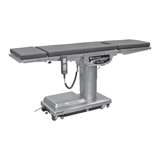
Page 7: 6700 Series Hercules General Purpose Surgical Table Specifications
Page 5 6700 Series Specifications 14-1/2" 12-1/2" 19-1/4" 23" 24-1/4" 14-1/2" 19-3/4" TOP VIEW 79" 60° 6" 22" 3" 90° 41" MAX 23" MIN 5-3/4" 8-1/2" 19" 37" SIDE VIEW END VIEW ETL LISTED CONFORMS TO UL STD 60601-1 CERTIFIED TO CAN/CSA STD C22.2 NO.601.1 Electrical Specifications Power requirements... -
Page 8: Section I Hydraulic System
Page 6 SECTION I HYDRAULIC SYSTEM 1-1. General b. Motor/Pump Assembly - A positive displace- ment gear type pump provides the necessary oil Electro-Hydraulic System pressure and volume. The hydraulic system (with the exception of the hy- c. Pressure Relief Valve - Provides an alternate draulic cylinders and hoses) is contained within the oil path when the hydraulic cylinders reach the end base of the table. -
Page 9: Component Operation
Page 7 1-2. Component Operation The main component of the valve is an adjustable spring loaded plunger that when it is pushed off from a. Motor/Pump Operation its seat by the oil pressure, the oil flows back into the reservoir. See figure 1-4. Turning the adjustment The motor/pump assembly is a gear type pump that nut clockwise increases the amount of oil pressure provides the oil pressure and volume for the entire... -
Page 10: Mini-Valves
Page 8 c. Mini-Valves the return oil. If the pump puts out more volume The operation of the mini-valves is identical for to a slave cylinder than is allowed by the speed all table functions except the elevation and brake control, the pressure relief valve opens and pro- circuits. - Page 11 Page 9 Mini-Valve Left Port Activated Mini-Valve Right Port Activated (See figure 1-7.) (See figure 1-6) Left Mini-Valve Port is Supply Line Right Mini-Valve Port is Supply Line Right Mini-Valve Port is Return Line Left Mini-Valve Port is Return Line INLET OUTLET OUTLET...
-
Page 12: Hydraulic Cylinders (Slave Cylinders)
Page 10 d. Hydraulic Cylinders (Slave Cylinders) 2. Trendelenburg Cylinder Assembly - The Tren- There are several different types of hydraulic cyl- delenburg tilt assembly consists of two cylinders, inders used in the table that activate the control pistons and connecting rods. The connecting rods functions. - Page 13 Page 11 4. Elevation Cylinder - This single action cylinder does not have hydraulic fluid on both sides of the piston. It depends on the weight of the table top as- sembly to lower it. The cylinder is set in the center of KIDNEY LIFT the elevation main column.
-
Page 14: Elevation Cylinder Return Circuit
Page 12 e. Elevation Cylinder Return Circuit A three-way (single check valve type) mini-valve 2. 3-way (single check valve type) mini-valve. controls both the elevation and return circuits. The elevation circuit operation within the mini-valve is 3. Manually controlled emergency brake re- identical to the operation of the four-way valves lease. -
Page 15: Emergency Brake Release
Page 13 h. Flex/Reflex System When activated, the return hydraulic circuit operates The Flex/Reflex system incorporates an additional similar to the elevation cylinder return circuit. Re- mini-valve which connects the trendelenburg and turn springs inside the single action brake cylinders back section hydraulic systems in a series. -
Page 16: Hydraulic Adjustments
PLUMBING BOLT Figure 1-18. 041905.033 The type of oil that should be used is SKYTRON P.N. D6-010-90 or equivalent. This is a very high quality Figure 1-19. hydraulic oil. The table requires approximately two quarts of oil to operate properly. Excercise caution when determining equivalance to avoid damage to 2. -
Page 17: Speed Controls
Page 15 d. Speed Controls The speed controls restrict the volume of oil returning Any control function should move in either direc-tion back to the reservoir thereby controlling the speed at the same rate. If the rate of a certain function of each control function. -
Page 18: Section Ii Mechanical Table Adjustments
Page 16 SECTION II MECHANICAL TABLE ADJUSTMENTS 2-1. Back Section Gear Mesh Adjustment Any twisting or flexing of the back section as it ap- proaches the stalled position indicates that one of The gear mesh is adjusted by the use of an ec- the cylinders is not reaching its fully extended posi- centric cam. -
Page 19: Head Section Adjustment
Page 17 2-3. Head Section Adjustment The head section can be adjusted to eliminate any flexing throughout it's range of travel. NOTE To adjust: The leg section cylinder eccentric cam is located under the nameplate on the Place the head section in level position and remove side casting. -
Page 20: Side Rails
Page 18 2-6 Casters Using a 5mm allen wrench, torque each bolt to 18 Clean and lubricate each of the casters. Remove any debris caught in the casters and old grease. N/meter (13.27 ft/lbs) on the head and foot end of the Trendelenburg cylinder following the star pattern Lubricate using a grease gun and conventional shown in Fig. -
Page 21: Section Iii Hydraulic Troubleshooting
Page 19 SECTION III HYDRAULIC TROUBLESHOOTING 3-1. Precautions 5. Is the problem no movement of a table surface Before attempting to troubleshoot any hydraulic or does the table surface lose position? problem on the table, please read through the pre- cautions and notes below. -
Page 22: Elevation Diagnosis Chart
Page 20 3-3. ELEVATION DIAGNOSIS CHART Reason Problem Pressure Relief Valve Not Set Properly Table will not elevate properly Low on Oil Spool Valve Not Centered Defective Pump Defective Mini-Valve Defective Solenoid or Wiring Defective Relay Box or Pendant Control Leaking Cylinder Hose Uneven Weight Distribution Incorrect Speed Adjustment... -
Page 23: Trendelenburg Diagnosis Chart
Page 21 3-4. TRENDELENBURG DIAGNOSIS CHART Problem Reason Trendelenburg function moves improperly Incorrect Speed Adjustment Spool Valve Not Centered Bad Check Valves Low on Oil Pinched Hose Defective Mini-Valve Pressure Relief Valve Not Set Properly Bad Solenoid or Wiring Defective Relay Box or Pendant Control Trendelenburg function chatters or loses position Defective or Dirty Check Valve Oil Leakage in Circuit... -
Page 24: Lateral Tilt Diagnosis Chart
Page 22 3-5. LATERAL TILT DIAGNOSIS CHART Problem Reason Lateral tilt function moves improperly Incorrect Speed Adjustment Spool Valve Not Centered Bad Check Valves Low on Oil Pinched Hose Defective Mini-Valve Pressure Relief Valve Not Set Properly Bad Solenoid Defective Relay Box or Pendant Control Lateral tilt function chatters or loses position Defective or Dirty Check Valves Oil Leakage in Circuit... -
Page 25: Flex System Diagnosis Chart
Page 23 3-6. FLEX SYSTEM DIAGNOSIS CHART Problem Reason Back Section or Trendelenburg function moves Incorrect Speed Adjustment (Trendelenburg, improperly Back section or Flex - check with gauge) NOTE Spool Valve Not Centered Bad Check Valves If Flex System does not function Low on Oil properly, check the back section and Pinched Hose... -
Page 26: Back Section Diagnosis Chart
Page 24 3-7. BACK SECTION DIAGNOSIS CHART Reason Problem Incorrect Speed Adjustment Back Section function moves improperly Spool Valve Not Centered Bad Check Valves Low on Oil Pinched Hose Defective Mini-Valve Pressure Relief Valve Not Set Properly Bad Solenoid Defective Relay Box or Pendant Control Kidney Bridge Raised Defective or Dirty Check Valves Back Section function chatters or loses position... -
Page 27: Leg Section Diagnosis Chart
Page 25 3-8. LEG SECTION DIAGNOSIS CHART Problem Reason Leg function moves improperly Incorrect Speed Adjustment Spool Valve Not Centered Bad Check Valves Low on Oil Pinched Hose Defective Mini-Valve Pressure Relief Valve Not Set Properly Bad Solenoid Defective Relay Box or Pendant Control Leg function chatters or loses position Defective or Dirty Check Valves Oil Leakage in Circuit... -
Page 28: Kidney Lift Diagnosis Chart
Page 26 3-9. KIDNEY LIFT DIAGNOSIS CHART Reason Problem Incorrect Speed Adjustment Kidney Lift moves improperly Spool Valve Not Centered Bad Check Valve Low on Oil Pinched Hose Defective Mini-Valve Pressure Relief Valve Not Set Properly Bad Solenoid Defective Relay Box or Pendant Control Defective or Dirty Check Valve Kidney Lift chatters or loses position OiI Leakage in Circuit... -
Page 29: Brake Circuit Diagnosis Chart
Page 27 3-10. BRAKE CIRCUIT DIAGNOSIS CHART Problem Reason Emergency Brake Release Valve Open or Defec- Brakes will not set properly tive Spool Valve Not Centered NOTE Bad Check Valve If brakes have been released with Low on Oil the Emergency Brake Release Valve, Pressure Relief Valve Not Set Properly brakes will not reset until BRAKE UN- Pinched Hose... -
Page 30: Flexible Hose Identification And Placement
Page 28 3-11. Flexible Hose Identification and Placement the hoses from the plumbing terminal to their re- spective hydraulic cylinders. Figure 3-9 shows the correct placement of the flexible hydraulic hoses The flexible hydraulic hoses used in the table are and their respective number codes. -
Page 31: Kidney Lift System
Page 29 3-12. Kidney Lift System The Kidney Lift cylinders are connected in series so that both cylinders operate simultaneously. Hydraulic pressure on one side of the lead piston causes the piston to move. The piston movement LEFT CYLINDER forces the hydraulic fluid on the other side of the piston through the system to the other cylinder. - Page 32 Page 30 b. Cylinder Adjustment If either of the kidney lift cylinders reaches the end 4. Leave the bypass valve open and activate of the down stroke before the other one, an adjust- "KIDNEY DOWN". Hydraulic pressure keeps the ment is needed. Use the following procedure to piston in chamber "C", the hydraulic fluid passes adjust the system.
- Page 33 Page 31 SOLENOID PENDANT RETURN COIL 24VDC CONTROL CIRCUIT HN10 HN11 MINI-VALVES BUZZER CN1B RELAY BOX CN1A 22 VAC FROM AUXILIARY TRANSFORMER SWITCHES CN11 BATTERIES CN10 120 VAC TO PUMP TRANSFORMER CIRCUIT BREAKER CAPACITOR/ RECTIFIER POWER CORD BASE CONNECTOR MAIN FOOT BATTERY POWER...
-
Page 34: Section Iv Electrical System
SECTION IV ELECTRICAL SYSTEM Page 32 4-1. General 4-2. Components The complete electrical system (with the excep-tion Refer to figure 4-1 for the relationship of the elec- of the hand-held pendant control and the return trical components. circuit micro-switches) is contained within the base of the table. -
Page 35: Section V Electrical Troubleshooting
SECTION V ELECTRICAL TROUBLESHOOTING Page 33 5-1. General 5-3. Main Switch The battery table components operate on 24VDC. The main power supply, 120 VAC, 60 HZ, comes The internal charging system also incorporates in through the power cord and through the components to transform the 120VAC input to Power Switch. -
Page 36: Batteries
Page 34 b. Test Results a. Battery System Test If the correct voltage is obtained, everything is 1. Disconnect the main power cord and using good up to this point and the problem would have a DC voltmeter, test each individual battery at its to be in another area. -
Page 37: Capacitor / Rectifier / Ac120V Transformer
Page 35 5-5. Capacitor / Rectifier / AC120V Transformer The Capacitor / Rectifier Unit contains the battery charging system as well as the components for AC120V operation (except the transformer). a. Transformer Test 1. Confirm 120VAC input at HN1 using Main Switch test in 5-3a. -
Page 38: Pendant Control
Page 36 NOTE Normal charging time for a fully dis- charged battery is approximately 8 hours. e. Charging Indicator Test Charging Indicator contains 10 LEDs, 3 red, 4 yel- low and 3 green. 041905.005 All Indicators illuminated indicates full charge. Figure 5-6 Indicators flash when charging is in process. - Page 39 If the correct readings are obtained, this part of the circuit is okay and the problem may be the Pendant Control or the Relay Box. Contact SKYTRON if all tests performed indicate that the problem is located in the Pendant Control.
-
Page 40: Auxiliary Switches
Page 38 5-7. Auxiliary Switches The following tests will determine if the auxiliary switches are functioning properly. a. Switch Test Disconnect connector CN2 at the Relay Box and using an ohmmeter check for continuity at the con- nector pins (pin 1A common) while activating the appropriate switch. -
Page 41: Relay Box
Page 39 BATTERY MODE TEST (main power OFF) 5-8. Relay Box The power supply is directly connected to the relay contacts. When these contacts are closed, 24 volts is supplied to the solenoids which are mounted on the hydraulic mini-valves. One relay is used to supply 1-RED (+) power to the pump/motor and is always activated 2-BLUE (-) - Page 42 Checking Output to Pendant Control The output to the Pendant Control can not be tested without specialized equipment. If all tests have been conducted and it appears that the Relay Box is faulty, contact SKYTRON.
-
Page 43: Main Wire Harness Continuity Tests
Page 41 5-9. Main Wire Harness Continuity Tests If correct meter readings are not received in tests between components, before replacing the com- ponents, test the Main Wire Harness to be sure all connectors and wires are making a good con- nection. -
Page 44: Solenoids
Page 42 5-10. Solenoids 1. Disconnect connectors CN1A and CN1B. Measure the resistance between the two pins The solenoids are energized by 24 volt potential at the connector for the solenoid in question as that is controlled by the relay box. The solenoid shown in figure 5-17. -
Page 45: Motor/Pump Assembly
Page 43 NOTE 1. Turn OFF both BATTERY and AC120V op- erating modes. Whenever there are several components of the same type, a defective unit 2. Use an ohmmeter to test for continuity be- can also be detected by substituting tween terminals 3 and 4 on the connector HN4. -
Page 46: Return-To-Level / Positioning Inhibit Micro-Switches
Page 44 5-12. Return-to-Level / Positioning Inhibit Micro-Switches. exceeds 20°. Likewise, Trendelenburg positioning The return-to-level feature is activated by a single is limited to 20° if lateral tilt positioning exceeds button on the pendant control and automatically 20°. An audible alarm will sound if the positioning levels the major table functions, lateral tilt, Trende- maximums are achieved. -
Page 47: Micro-Switch Troubleshooting
Page 45 5-13. Troubleshooting All of the micro-switches are connected to the relay If a problem is suspected in the return / positioning box via a wiring harness and the micro-switch riser circuits, disconnect the connector CN10 from the cord using connectors CN10, HN10 and HN11. Relay Box to eliminate the circuits. - Page 48 Page 46 a. Switch Test NOTE Turn Main Power ON, lock the table brakes, and If you do not receive the proper conti- place the table top sections in a level position with nuity results at connector CN10 it does the Kidney Lift down.
- Page 49 Page 47 CAUTION Incorrect "Inhibit" micro-switch adjust- ment may allow component collision causing table damage and compromise patient safety. BACK SECTION LEG SECTION NS-2 LS-2 NS-1 BLACK PURPLE/ WHITE WHITE/BLACK WHITE (HN10) CN10 (HN10) CN10 (HN11) RISER CORD RISER CORD CN10 (HN10) ORANGE...
- Page 50 Page 48 CAUTION Incorrect "Inhibit" micro-switch adjust- ment may allow component collision causing table damage and compromise patient safety. BACK SECTION LEG SECTION LS-3 LS-3 NS-3 NS-3 NS-4 WHITE NS-4 YELLOW BROWN GREEN (HN10) CN10 (HN10) CN10 (HN11) RISER CORD RISER CORD BLUE CN10...
- Page 51 Page 49 BACK SECTION NS-6 LEG SECTION NS-6 PURPLE BROWN/WHITE BLUE PINK NS-5 NS-5 (HN10) (HN10) CN10 RISER CORD CN10 (HN10) CN10 (HN10) When the Back Section is Down, When the Back Section is Up, NS-5 brings the Back Section Up to level. NS-6 brings the Back Section Down to level.
- Page 52 Page 50 LEG SECTION BACK PINK/WHITE SECTION NS-7 NS-7 BLACK/WHITE GRAY GRAY NS-8 NS-8 BLACK (HN10) PINK/WHITE (HN11) CN10 GRAY (HN11) RISER CORD CN10 GRAY (HN10) CN10 BLACK (HN10) BLACK/WHITE When the Leg Section is Down, When the Leg Section is Up, NS-7 brings the Leg Section Up to level.
- Page 53 Page 51 b. Switch Adjustment. If proper readings are not obtained during test or if table does not properly return to level, use the following procedure to adjust the switches. 1. Apply table brakes and (using a level) level 3. To adjust the Leg Section switches remove the table top using the TRENDELENBURG and seat section top, loosen the 2 phillips head screws LATERAL-TILT function buttons on the pendant...
-
Page 54: Appendix
Page 52 i = Inspect APPENDIX: MODEL 6700 SERIES MAINTENANCE MATRIX r = Replace COMPONENT REFERENCE YEAR YEARS YEARS YEARS YEARS Check for Hydraulic leaks Pg. 3; 19 (3-1 thru 3-10) Check Lateral Tilt Housing bolts Pg. 22 Check Side Rails & Gravity Stops Pg. - Page 55 Page 53 i = Inspect APPENDIX: MODEL 6700 SERIES MAINTENANCE MATRIX r = Replace COMPONENT REFERENCE YEAR YEARS YEARS YEARS YEARS Brake Cylinders Pg. 12 (1-2d,6) Emergency Brake Release Valve Pg. 14 (1-2g) Pump/Motor Assembly Pg. 7 (1-1b); 8 (1-2a); 42 (5- 9b);...
- Page 56 5085 Corporate Exchange Blvd. S.E. Grand Rapids, MI 49512 • 1-616-656-2900 • FAX 1-616-656-2906...
Need help?
Do you have a question about the HERCULES 6700 Series and is the answer not in the manual?
Questions and answers