Table of Contents
Advertisement
Quick Links
10014566-A
Safety, Operation, & Maintenance Manual
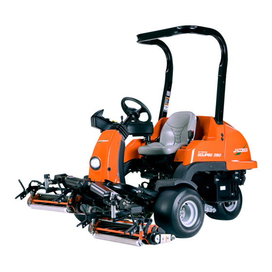
ECLIPSE 360 RIDING GREENS MOWER
LITHIUM BATTERY POWER
Product Code: 10029194
Series: CAG
WARNING
Warning: If incorrectly used, this machine can
cause severe injury. Those who use and maintain
this machine should be trained in its proper use,
warned of its dangers, and must read the entire
manual before attempting to set up, operate, adjust,
or service the machine.
When Performance Matters.
™
GB
Advertisement
Table of Contents
Troubleshooting

Related Manuals for Jacobsen ECLIPSE 360


Summary of Contents for Jacobsen ECLIPSE 360
- Page 1 10014566-A Safety, Operation, & Maintenance Manual ECLIPSE 360 RIDING GREENS MOWER LITHIUM BATTERY POWER Product Code: 10029194 Series: CAG WARNING Warning: If incorrectly used, this machine can cause severe injury. Those who use and maintain this machine should be trained in its proper use,...
- Page 2 FOREWORD This manual contains adjustment, maintenance, troubleshooting instructions, and parts list for your new machine. This manual should be stored with the equipment for reference during operation. Before you operate your machine, you and each operator you employ should read the manual carefully in its entirety. By following the safety, operating, and maintenance instructions, you will prolong the life of your equipment and maintain its maximum efficiency.
-
Page 3: Table Of Contents
TABLE OF CONTENTS SAFETY OVERLOAD PROTECTION........49 MOWING............... 49 HOW TO OPERATE SAFELY ........ 5 HILLSIDE OPERATION ........51 IMPORTANT SAFETY NOTES ......8 LOADING MOWER ON TRAILER ......53 SPECIFICATIONS TOWING MOWER ..........54 DAILY MAINTENANCE......... 56 HOW TO OPERATE SAFELY ........ 9 PRODUCT IDENTIFICATION ........ - Page 4 TABLE OF CONTENTS REEL ASSEMBLY ..........79 REEL BEARING ........... 80 REEL STABILIZER RODS........81 BEDKNIFE ADJUSTER SPRING ......81 BEDKNIFE ADJUSTER TENSION ....... 82 GRINDING BEDKNIFE ......... 82 STEERING CHAIN TENSION ......82 ARMREST HEIGHT ADJUSTMENT..... 83 ARMREST PIVOT..........83 GRASS CATCHER YOKE ADJUSTMENT ...
-
Page 5: Safety
Know the location and correct operation of controls. Operators without experience must receive instruction from another person that knows the correct operation of the equipment before you operate the mower. Only use parts, accessories and attachments approved by Jacobsen. Safe Operation •... - Page 6 SAFETY Operation • Never operate the engine without enough ventilation or in an enclosed area. The carbon monoxide in the exhaust fumes can increase to dangerous levels. • Never carry passengers. Keep other persons or animals away from the mower. •...
- Page 7 • Do not remove the ROPS from the mower. • Jacobsen must approve any changes to the ROPS. Maintenance and Storage • Before you clean, adjust or repair this equipment, push PTO switch to the OFF position, lower the cutting unit to the ground, engage the parking brake, stop the engine and remove the key.
-
Page 8: Important Safety Notes
Adjustments and maintenance should always be performed by a qualified technician. If additional information or service is needed, contact your Authorized Jacobsen Dealer who is kept informed of the latest methods to service this equipment and can provide prompt and efficient service. -
Page 9: Specifications
Know the location and correct operation of controls. Operators without experience must receive instruction from another person that knows the correct operation of the equipment before you operate the mower. Only use parts, accessories and attachments approved by Jacobsen. WARNING EQUIPMENT OPERATED INCORRECTLY OR WITHOUT TRAINING CAN BE DANGEROUS. -
Page 10: Vibration Level
Information Supplied for Physical Agents Directive 2002/44/EC By reference to: Hand/Arm Standards: BS EN ISO 5349-1 (2001) BS EN ISO 5349-2 (2001) Eclipse 360 Hand/Arm Maximum Left Hand or Right Hand Accelerations m/s Acceleration Level Mean Value of X, Y, Z Aeq Battery Powered Mowers 0.75 ±... - Page 11 SPECIFICATIONS Weights and Dimensions Dimensions: ..........Inches (cm) Length - Grass Catchers On ......101 (256.5) Height - Top of ROPS ........79.3 (201.4) Wheel Base............. 52 (132.1) Width - Mowing Position....... 67.7 (172.0) Width - Wheel..........59 (150.0) Turning Radius ..........18 (45.7) Weights: ............Lb (kg)
-
Page 12: Accessories & Support Literature
ACCESSORIES & SUPPORT LITERATURE _______________________________ Contact your area Jacobsen Dealer for a complete listing of accessories and attachments. CAUTION Use of other than Jacobsen authorized parts and accessories may cause personal injury or damage to the equipment. Accessories Traction Pedal Test Connector......4225240 Field Test Kit.... - Page 13 SPECIFICATIONS TrueSet™ 11 Blade Reel ......62832 TrueSet™ 15 Blade Reel ......62833 Reel Conversion Kit........4218680 Rollers Grooved Front Roller........68527 Solid Roller ..........68530 Grooved Front Roller (Steel) ......68613 Grooved Front Roller (Aluminum) ....68614 High Cut Roller 15/16 in.
- Page 14 SPECIFICATIONS Notes: en-14 Safety, Operation, & Maintenance Manual Lithium...
-
Page 15: Decals
Only use parts, accessories and attachments approved by Jacobsen. INSTRUMENT PANEL ________________________________________________ Familiarize yourself with the following decals. They are critical to the safe operation of the mower. REPLACE DAMAGED DECALS IMMEDIATELY. - Page 16 DECALS Danger To avoid injury when working with battery: 1.Always connect the black (-) ground last and remove it first. 2.Keep sparks and flames away, and avoid contact with acid. To avoid injury when jumping battery: 1.Connect positive (+) terminal to positive (+) terminal. 2.Connect negative (-) terminal on good battery to frame of vehi- cle that has dead battery.
- Page 17 DECALS WARNING Read all mower manuals before operating or per- forming any maintenance. 4181860 IMPORTANT DO NOT USE STARTING ASSIST FLUIDS Use of starting assist fluids in the air intake system may be potentially explosive or cause a “runaway” engine condition. This could result in serious engine damage. 4181863 Familiarize yourself with the following decals.
- Page 18 DECALS Notes: en-18 Safety, Operation, & Maintenance Manual Lithium...
-
Page 19: Controls
Know the location and correct operation of controls. Operators without experience must receive instruction from another person that knows the correct operation of the equipment before you operate the mower. Only use parts, accessories and attachments approved by Jacobsen. ICONS Read Manual... -
Page 20: Instrument Panel
CONTROLS WARNING Never attempt to drive the mower unless you have read the Safety and Operation Man- ual and know how to operate all controls correctly. Familiarize yourself with the icons shown above and what they represent. Learn the location and purpose of all of the controls and gauges before operating this mower. INSTRUMENT PANEL LCD Display Unit (LDU) Used to display and set operating conditions. - Page 21 CONTROLS Light Switch (G) Controls operation of the work lights. Press front of switch to turn lights ON. Press rear of switch to turn lights OFF. Switch is not active if system power switch is not in RUN position. System Power Switch (H) Used to energize the electrical system and start the hybrid engine if installed.
-
Page 22: Operator Controls
CONTROLS OPERATOR CONTROLS Forward Traction Pedal (K) Press forward traction pedal down to move the mower forward. The further the pedal is pressed, the faster the mower will travel. Reverse Traction Pedal (L) Press reverse traction pedal down to move the mower in reverse. The further the pedal is pressed, the faster the mower will travel. -
Page 23: Operator Convenience
CONTROLS OPERATOR CONVENIENCE MCU Access Panel (R) Remove thumbscrew and lift up on front of access panel to view MCU diagnostic lights. Always secure access panel with thumbscrew when operating. Cup Holder (S) Used to hold a beverage cup for the operator or may be used as additional storage pocket. Rubber portion of cup holder is removable for cleaning purposes. - Page 24 CONTROLS Tie Down (AD) Used to secure mower to trailer for transport. Fig. 3 en-24 Safety, Operation, & Maintenance Manual Lithium...
-
Page 25: Lcd Display Unit (Ldu)
(AN) to go forward in the display list or increase setting value, and push the left orange button (AM) to go back in the dis- play list or decrease setting value. The black button (AL) is used to select, reset or change values. JACOBSEN 12 V VERSION X.XX... -
Page 26: Display Operating Hours
Hours hours will be displayed for 1 minute. 00000.0 START UP SCREEN __________________________________________________ The Jacobsen start up screen will display for 5 seconds when the system power switch is turned from the OFF to the RUN Start up JACOBSEN position. The software version of the controllers is displayed... - Page 27 CONTROLS Mode 1 Mode 2 Mode 3 Mode 4 Mode 5 Mode 6 Setting Reel Reel Roller Verticut Spiker Other Reel Speed 2200 rpm 2200 rpm 1800 rpm 2200 rpm Number of reel blades FOC Setting 0.160 in. 0.196 in. (0.4064 (0.4967 Reels Disabled s...
-
Page 28: Operator Mode
CONTROLS OPERATOR MODE ___________________________________________________ Operator mode is used by the opera- tor to view attachment mode, system Operator Operator JACOBSEN JACOBSEN voltage information, travel speed, REVIEW REVIEW mode mode reel motor current, reel motor speed, ALARMS? ALARMS? switch status, operation hours, and... -
Page 29: Maintenance Mode
NOTE: The Maintenance Mode PIN can be customized to a setting of your choice. Please contact your Jacob- sen Dealer or Jacobsen Technical Support for complete instructions. System voltage, travel speed, reel motor current draw and reel motor speed screens are the same as for Operator Mode. - Page 30 CONTROLS Maintenance Hours To display maintenance hours, press either of the orange buttons (AM or AN) on the LDU until the maintenance hours screen is on the LCD display. To reset maintenance hours, press the black button (AL). Select Units To set the display units, press either of the orange buttons (AM or AN) on the LDU until the SELECT UNITS? screen is on the LCD display.
- Page 31 CONTROLS Maximum Transport Speed To set the maximum transport speed, press either of the orange buttons (AM or AN) on the LDU until the set MAX SPEED screen is on the LCD display. Press the black button (AL) to enter set mode. Use the orange buttons to raise (AN) or lower (AM) the maximum transport speed to the desired speed.
- Page 32 CONTROLS Mower Attachment Mode To set the mower attachment mode, press either of the orange buttons (AM or AN) until the MODE CHANGE? screen is on the lcd display. Press the back button (AL) to enter set mode. Press the right orange button until the desired mode is on the screen, then press the black button to select it.
- Page 33 CONTROLS Maintenance MAINTENANCE Displays temp. TCU HS 032F Displays reel REEL MOTOR Mode MODE for TCU and motor status MOTOR 032F traction motor Displays system SYSTEM VOLTS Displays current Change reel 1 = REEL voltage 48.0 VDC TRACTION for traction mode MODE CHANGE? 000 AMPS...
-
Page 34: Frequency Of Cut
CONTROLS FREQUENCY OF CUT ________________________________________________ The FOC (Frequency of Cut) is the distance, in inches (cm), the machine travels forward between reel blades contacting the bedknife. The FOC can be adjusted either by changing the Fixed FOC setting or by changing the maximum mow speed and the fixed reel speed on the LCD display. - Page 35 CONTROLS NOTE: Mow speed is measured in mph (kph), FOC is measured in inches (millimeters). 15 Blade Reel FOC Table Reel RPM Speed 1800 1850 1900 1950 2000 2050 2100 2150 2200 Inch Inch Inch Inch Inch Inch Inch Inch Inch (KPH) (cm)
- Page 36 CONTROLS Reel RPM Speed 1800 1850 1900 1950 2000 2050 2100 2150 2200 Inch Inch Inch Inch Inch Inch Inch Inch Inch (KPH) (cm) (cm) (cm) (cm) (cm) (cm) (cm) (cm) (cm) 4.50 0.176 0.171 0.167 0.162 0.158 0.155 0.151 0.147 0.144 (7.24)
- Page 37 CONTROLS 11 Blade Reel FOC Table Reel RPM Speed 1800 1850 1900 1950 2000 2050 2100 2150 2200 Inch Inch Inch Inch Inch Inch Inch Inch Inch (KPH) (cm) (cm) (cm) (cm) (cm) (cm) (cm) (cm) (cm) 0.053 0.052 0.051 0.049 0.048 0.047...
- Page 38 CONTROLS Reel RPM Speed 1800 1850 1900 1950 2000 2050 2100 2150 2200 Inch Inch Inch Inch Inch Inch Inch Inch Inch (KPH) (cm) (cm) (cm) (cm) (cm) (cm) (cm) (cm) (cm) 4.25 0.227 0.221 0.215 0.209 0.204 0.199 0.194 0.190 0.185 (6.84)
- Page 39 CONTROLS 9 Blade Reel FOC Table Mow Speed Reel RPM 1800 1850 1900 1950 2000 2050 2100 2150 2200 Inch Inch Inch Inch Inch Inch Inch Inch Inch (KPH) (cm) (cm) (cm) (cm) (cm) (cm) (cm) (cm) (cm) 0.065 0.063 0.062 0.060 0.059...
- Page 40 CONTROLS Mow Speed Reel RPM 1800 1850 1900 1950 2000 2050 2100 2150 2200 Inch Inch Inch Inch Inch Inch Inch Inch Inch (cm) (cm) (cm) (cm) (cm) (cm) (cm) (cm) (cm) (KPH) (6.84) (7.037) (6.847) (6.666) (6.495) (6.333) (6.179) (6.031) (5.891) (5.757)
- Page 41 CONTROLS 7 Blade Reel FOC Table Reel RPM Speed 1800 1850 1900 1950 2000 2050 2100 2150 2200 Inch Inch Inch Inch Inch Inch Inch Inch Inch (KPH) (cm) (cm) (cm) (cm) (cm) (cm) (cm) (cm) (cm) 0.084 0.082 0.079 0.077 0.075 0.074...
-
Page 42: Electronic Traction Control System
CONTROLS Reel RPM Speed 1800 1850 1900 1950 2000 2050 2100 2150 2200 Inch Inch Inch Inch Inch Inch Inch Inch Inch (KPH) (cm) (cm) (cm) (cm) (cm) (cm) (cm) (cm) (cm) 4.25 0.356 0.347 0.337 0.329 0.321 0.313 0.305 0.298 0.291 (6.84) -
Page 43: Lift System
CONTROLS LIFT SYSTEM _______________________________________________________ The Eclipse 360 lift system operates in one of two modes, service mode and mow mode, depending on the position of the mow switch (B). Service Mode - Service mode is active with mow switch (B) in OFF (down) position and parking brake engaged. Service mode is used to raise or lower the individual reels for servicing, without activating reel motors. - Page 44 CONTROLS Notes: en-44 Safety, Operation, & Maintenance Manual Lithium...
-
Page 45: Operations
OPERATION OPERATIONS DAILY INSPECTION __________________________________________________ CAUTION The daily inspection should be performed only when the system power is off. Turn mow switch OFF, lower reels to the ground, turn system power switch to OFF position, and remove the key. Perform a visual inspection of the entire unit, look for signs of wear, loose hardware, and missing or damaged com- ponents. -
Page 46: Operating Procedures
OPERATION Interlock System Check Test Operator Traction Pedal Mow Switch System Seated in Neutral Starts The mow, traction, and steering functions are disabled without operator in seat. ... -
Page 47: Starting
Sit in operator’s seat, make sure mow switch is OFF, and traction pedal is in Neutral. See INSTRUMENT PANEL on page 20, See OPERATOR CONTROLS on page 22. Turn system power switch to RUN. Steering controller will initialize, LDU will display Jacobsen start up screen, and all lights on LDU will be on for two seconds. -
Page 48: Stopping / Parking
OPERATION Fig. 1 STOPPING / PARKING ________________________________________________ To stop: Remove your foot from traction pedal, regen braking will start, bringing the mower to a complete stop. When mower stops, move the parking brake switch to the ON position. The parking brake will engage and the parking brake light on the LDU will turn on. -
Page 49: To Drive / Transport
To reset an overload fault condition, the mower must be shut down and re-started. If the problem persists, inspect the device and the electrical system to determine the cause of the overload or contact an authorized Jacobsen dealer. MOWING ___________________________________________________________... - Page 50 Stopping the mower on a wet green may cause wheel indentations. NOTICE When verticutting with the Eclipse 360 Jacobsen recommends setting the reel speed at 1800 rpm. If the reel motor temperature or current exceeds lim- its, reduce ground speed of mower, reduce reel speed, or adjust verticutter depth.
-
Page 51: Hillside Operation
OPERATION HILLSIDE OPERATION _______________________________________________ WARNING To minimize the possibility of overturning, the safest method for operating on hills and terraces is to travel up and down the face of the slope (vertically), not across the face (horizontally). Avoid unneces- sary turns, travel at reduced speeds, and stay alert for hidden hazards and drop offs. - Page 52 OPERATION How to calculate a slope Tools Required: Level (A), either ....... 1 yard, or 1 meter long. Tape measure (B)............1. With the level (A) positioned horizontally, measure the distance (C) with tape measure (B). Use the chart to calculate either the slope angle or the % grade of the slope (D). Fig.
-
Page 53: Loading Mower On Trailer
OPERATION Height (C) Result (D) Millimeters with 1 Meter Level Inches with 1 Yard Level (A) Slope in Degrees Slope Grade % 31.0 60.0 34.8 69.4 38.7 80.0 39.8 83.3 42.0 1000 45.0 LOADING MOWER ON TRAILER _______________________________________ Use care when loading and unloading mower onto trailer. Fasten mower to trailer, using tie downs on left and right side and rear of mower, to prevent mower from rolling or shifting during transport. -
Page 54: Towing Mower
OPERATION WARNING To prevent injury, keep bystanders away when load- ing or unloading a disabled mower on trailer. Mower brakes have been disabled and may not be used to stop mower. Do not attempt to roll mower down trailer ramp with- out use of winch or similar device to restrain mower. - Page 55 OPERATION • After towing mower, remove tow bar accessory, attach steering chain, remove brake release harness, connect brake electrical connector (ZX), and connect battery pack connector. WARNING Do Not operate mower with parking brake manually disengaged. Remove brake release harness and connect steer- ing chain before returning mower to normal opera- tion.
-
Page 56: Daily Maintenance
OPERATION DAILY MAINTENANCE ________________________________________________ IMPORTANT: For more detailed maintenance information, adjustments and maintenance/lubrication charts, see the Parts & Maintenance manual. Park the mower on a flat, level surface. Fully lower the reels to the ground, stop the engine and remove key from ignition switch. -
Page 57: Maintenance And Lubrication Charts
MAINTENANCE & LUBE CHARTS MAINTENANCE AND LUBRICATION CHARTS GENERAL __________________________________________________________ WARNING Before you clean, adjust, or repair this equipment, disengage all drives, lower implements to the ground, engage parking brake, stop engine and remove key from ignition switch to prevent injuries •... -
Page 58: Lubrication Chart
MAINTENANCE & LUBE CHARTS Note: Loose fitting reel motor couplers will damage the motor shaft and this will not be covered under war- ranty after 1 year or 300 hours whichever occurs first. • Manual grease gun with NLGI Grade 2 (Service Class LB). •... -
Page 59: Batteries
BATTERIES BATTERIES BATTERY SAFETY___________________________________________________ Charging should be performed when ambient temperatures are between 40°F and 110°F (4°C and 42°C). The battery pack may be charged or topped off after every use. The battery management system (BMS) and charger cooperate to make sure that charging occurs at the proper rate for the battery temperature. - Page 60 BATTERIES The storage time for properly charged Lithium-Ion batteries supplied with this vehicle varies based on the ambient tem- perature. Temperature Length of Storage Time -22°F to -4°F (-30°C to -20°C) One month at 100% battery charge, all accessories turned off. -4°F to 113°F (-20°C to 45°C) Six months at 100% battery charge, all accessories turned off.
-
Page 61: Battery Charging And Maintenance
BATTERIES BATTERY CHARGING AND MAINTENANCE ______________________________ The charger should be operated in accordance with the charger manufacturer’s instructions. Never charge batteries in a hazardous environment. Risk of electric shock. Connect the charger power cord to an outlet that is correctly installed and connected to an electrical ground according to all codes and regulations. - Page 62 BATTERIES Notes: en-62 Safety, Operation, & Maintenance Manual Lithium...
-
Page 63: Maintenance
Always use jack stands. • Adjustment and maintenance should always be performed by a qualified technician. If proper adjustments cannot be made, contact an Authorized Jacobsen Dealer. • Inspect the equipment on a regular basis, establish a maintenance schedule and keep detailed records. -
Page 64: Axle Hub Inspection
MAINTENANCE AXLE HUB INSPECTION ______________________________________________ The following procedure must be performed once a year or every 300 hours, whichever comes first. Remove and discard cotter pin (A) from the axle. With tire on ground, break castle nut (B) free. Do not fully remove the castle nut. Raise the mower and support front axle on jack stands. -
Page 65: Parking Brake Inspection
MAINTENANCE PARKING BRAKE INSPECTION ________________________________________ Refer to the parts catalog as an aid for the removal and assembly of components. NOTE: The motor brake may be removed with the front axle motor in the vehicle. Use a dust mask and gloves to protect lungs and hands from brake dust. Disconnect the main power connector. - Page 66 MAINTENANCE Install the eleven clutch springs (P) into the brake hous- ing (R). 10. Assemble the pressure plate (N) into the brake housing (R). Align marks (F). 11. Place brake disk and hub (L) on the pressure plate (N). Brake disk should be centered on the pressure plate. 12.
-
Page 67: Lift Actuator Calibration
Park the mower on a flat and level surface. Enter Maintenance Mode. See Maintenance Mode on page 29.. Press either of the orange buttons (AM or AN) on the JACOBSEN 12 V LDU until the ACTUATOR CALIBRATE? screen is on VERSION X.XX the LCD display. -
Page 68: Backlapping And Grinding
MAINTENANCE BACKLAPPING AND GRINDING ________________________________________ To backlap: Park the mower on a flat and level surface. Enter Maintenance Mode. See Maintenance Mode on page 29.. Press either of the orange buttons (AM or AN) on the LDU until the BACKLAP ENABLE? screen is on the LCD display. -
Page 69: Tires
MAINTENANCE TIRES _____________________________________________________________ 1. Keep tires properly inflated to prolong tire life. Check inflation pressure while the tires are cool. Inspect tread wear. 2. Check the pressure with an accurate, low pressure tire gauge. 3. Keep tires inflated to: Front ......16 psi (1.1 BAR) Rear...... -
Page 70: Storage
Clean all plastic or rubber components with a mild soap solution and warm water, or use commercially available vinyl/rubber cleaners. • Repair damaged metal surfaces and use Jacobsen touch-up paint. Wax the equipment for maximum paint protec- tion. CAUTION Clean grass and debris from cutting units, drives, muffler, and engine to prevent fires. -
Page 71: Electrical System
• Check the interlock system, fuses, and circuit breakers regularly. • If the interlock does not function properly and the problem cannot be corrected, contact an authorized Jacobsen Dealer. • Keep the wire harness and all individual wires away from moving parts to prevent damage. -
Page 72: Pdu And Controller Locations
ELECTRICAL SYSTEM Controller Location/Function 3WD Controller Located at the rear of the unit below the hood. 3WD controller is used to control the rear wheel motor. The 3WD controller has one green light for diagnostics. (3WD) PDU AND CONTROLLER LOCATIONS___________________________________ Power Distribution Unit (PDU) Circuit Breakers Used to protect electrical system. - Page 73 ELECTRICAL SYSTEM Traction Controller Steering Controller Braking Resistor RCU Controller Diagnostic Lights Diagnostic Light Diagnostic Light Controller 3WD Controller Diagnostic Light 12VDC Steering PDU Manual Reset Circuit Breakers MCU Controller Diagnostic Lights Figure 0A Safety, Operation, & Maintenance Manual en-73 Lithium...
-
Page 74: Rcu Controller Lights
ELECTRICAL SYSTEM RCU CONTROLLER LIGHTS ___________________________________________ The RCU controller is a solid state device that monitors and controls reel and lift electrical functions. The RCU communi- cates with the MCU via the CAN network. Each input and output signal is displayed through lamps located on front face of the controller. An active circuit will turn an input lamp on, an inactive circuit will turn a lamp off. -
Page 75: Mcu Controller Lights
ELECTRICAL SYSTEM MCU CONTROLLER LIGHTS___________________________________________ The MCU controller is a solid state device that monitors and controls mower functions. The MCU communicates with the other controllers via the CAN network. Each input and output signal is displayed through lamps located on top face of the controller. A closed input switch indi- cates an active circuit and will turn an input lamp on, an open switch an inactive circuit and will turn a lamp off. -
Page 76: Pdu
ELECTRICAL SYSTEM PDU _______________________________________________________________ The PDU is located to the left of the operator seat, under the MCU, and is used to switch 48V and 12V motor/controller outputs on or off. Three circuit breakers are located on the rear of the PDU. Before working on, or opening the PDU, shut mower off, remove key, disconnect 48 volt battery connector, and discon- nect 12 volt battery connector (Hybrid mowers). -
Page 77: Adjustments
Always use jack stands. • Adjustments and maintenance should always be performed by a qualified technician. If proper adjustment cannot be made, contact an authorized Jacobsen Dealer. • Replace, do not adjust, worn or damaged components. -
Page 78: Bedknife Adjustment
ADJUSTMENTS • A flat surface of at least 1/32 in. (0.08 cm) minimum must be maintained on the front face of the bedknife. Use a standard flat file to dress the bedknife. • If wear or damage is beyond the point where the reel or bedknife can be corrected by the lapping process, they must be reground. -
Page 79: Cutting Height
ADJUSTMENTS CUTTING HEIGHT ___________________________________________________ Note: Always make the reel to bedknife adjustment before adjusting height of cut. See Bedknife-To-Reel on page 77 and See Bedknife Adjustment on page 78. Set desired cutting height on the gauge (E). • Measure distance between the underside of screw head and gauge block surface (F). -
Page 80: Reel Bearing
ADJUSTMENTS 10. Route left front reel motor harness along lift yoke and under lift arm. Open connector cover (AU) and assemble motor harness to mower harness. Check to be certain harness does not contact moving parts, and secure har- Right ness to lift arm using one cable tie (AW) and lift yoke Reel using two cable ties (AV). -
Page 81: Reel Stabilizer Rods
ADJUSTMENTS REEL STABILIZER RODS _____________________________________________ The reel stabilizer rods help keep the reels level when raising or lowering reels or making turns. Pre-Adjustment On the end of the reel stabilizer rod with the springs and lock collar, the adjustment is set at the factory, and should not need to be changed. -
Page 82: Bedknife Adjuster Tension
ADJUSTMENTS BEDKNIFE ADJUSTER TENSION _______________________________________ NOTICE Over tightening slotted nut (S) will make bedknife adjuster rod (T) difficult to adjust. Remove cotter pin (U) and fully loosen, then tighten slot- ted nut (S) to remove clearance (no end play) between components. -
Page 83: Armrest Height Adjustment
ADJUSTMENTS ARMREST HEIGHT ADJUSTMENT ______________________________________ The armrest has three available height settings for operator convenience. To adjust armrest height: Shut mower off and remove key. Remove three bolts (V) from bracket on right side of seat. Raise or lower armrest as needed until another set of holes in armrest bracket line up with seat bracket. -
Page 84: Hood Stops
ADJUSTMENTS HOOD STOPS _______________________________________________________ Adjust position of hood stop bumpers (Z) as required so hood contacts bumpers with approximately 1/8 in. (0.3 cm) clearance between hood and cowlings. Adjust left and right side bumpers as required so hood is level. Test operation of hood latch. -
Page 85: Headlight Adjustment
ADJUSTMENTS HEADLIGHT ADJUSTMENT ___________________________________________ Headlight has four adjustment positions to change distance head light beam lights up. To Adjust headlight: Remove access plug (AM) from left side of steering col- umn. Raise or lower adjustment tab (AN) until headlight latches in desired detent position. Insert access plug. -
Page 86: Torque Specification
All torque values included in these charts are approximate and are for reference only. Use of these torque values is at your sole risk. Jacobsen is not responsible for any loss, claim, or damage arising from the use of these charts. Extreme caution should always be used when using any torque value. -
Page 87: Specific Torque
ADJUSTMENTS METRIC FASTENERS Non Critical Fasteners 10.9 12.9 into SIZE UNITS Aluminum Lubri- Lubri- Lubri- Lubri- cated cated cated cated Nm (in- – – – – – – 3.83 (34) 5.11 (45) 2.0 (18) Nm (in- 1.80 (16) 2.40 (21) 4.63 (41) 6.18 (54) 6.63 (59) 8.84 (78) 7.75 (68) 10.3 4.0 (35) (910 Nm (in-... - Page 88 ADJUSTMENTS Notes: en-88 Safety, Operation, & Maintenance Manual Lithium...
-
Page 89: Ldu Error Codes
LDU ERROR CODES LDU ERROR CODES GENERAL INFORMATION _____________________________________________ When the Eclipse mower encounters an error or fault in one of the controllers, an error code will display on the LDU, and certain machine functions may shut down. Record any error codes that appear on the LDU, and notify maintenance at the end of the day. Refer to the following list for LDU error codes and machine functions. -
Page 90: Reel Control Unit Error Codes
LDU ERROR CODES REEL CONTROL UNIT ERROR CODES __________________________________ RCU error codes are displayed on the LDU as a message. Alarm Caution Engine Traction Sound- Mow Stop Stop Stop LDU Error Message Error Description Yes No Yes No Yes No Yes No Left Reel Motor Temperature above ... - Page 91 LDU ERROR CODES Alarm Caution Engine Traction Sound- Mow Stop Stop Stop LDU Error Message Error Description Yes No Yes No Yes No Yes No Right Reel Motor current over 35 Amps for 30 seconds. Shut mower RIGHT REEL off, and remove key.
- Page 92 LDU ERROR CODES Alarm Caution Engine Traction Sound- Mow Stop Stop Stop LDU Error Message Error Description Yes No Yes No Yes No Yes No Center Actuator Overcurrent. Shut mower off, and remove key. Check C ACTUATOR grass catcher for excessive weight.
-
Page 93: Traction & Steering Controller Error Codes
LDU ERROR CODES Alarm Caution Engine Traction Sound- Mow Stop Stop Stop LDU Error Message Error Description Yes No Yes No Yes No Yes No Right actuator did not reach position within 6 seconds. Shut mower off, and CHECK RIGHT remove key. - Page 94 LDU ERROR CODES Alarm Caution Engine Traction Sound- Mow Stop Stop Stop LDU Error Code Description Yes No Yes No Yes No Yes No Phase UW Not Connected: A startup check of the motor connec- TRACTION tions measured current i phase U to FAULT 2317 be under the defined limit.
- Page 95 LDU ERROR CODES Alarm Caution Engine Traction Sound- Mow Stop Stop Stop LDU Error Code Description Yes No Yes No Yes No Yes No PWM Unexpected Off: TRACTION The power stage was unexpectedly FAULT 2360 turned off. STEERING FAULT 2360 3WD TRACTION FAULT 2360 PWM Unexpected Off Glitch:...
- Page 96 LDU ERROR CODES Alarm Caution Engine Traction Sound- Mow Stop Stop Stop LDU Error Code Description Yes No Yes No Yes No Yes No DC Voltage is above the High Trip level. Shut mower off, then restart. If TRACTION fault returns, mower must be towed FAULT 3211...
- Page 97 LDU ERROR CODES Alarm Caution Engine Traction Sound- Mow Stop Stop Stop LDU Error Code Description Yes No Yes No Yes No Yes No 5V C Out of Range: TRACTION The internal 5V C is out of range. FAULT 3304 The valid range is 4.5V to 5.5V.
- Page 98 LDU ERROR CODES Alarm Caution Engine Traction Sound- Mow Stop Stop Stop LDU Error Code Description Yes No Yes No Yes No Yes No Heatsink temperature is above 185° F (85° C). Shut mower off and wait ten TRACTION minutes.
- Page 99 LDU ERROR CODES Alarm Caution Engine Traction Sound- Mow Stop Stop Stop LDU Error Code Description Yes No Yes No Yes No Yes No Short Circuit Ch1: TRACTION A hardware short circuit is detected. FAULT 5411 Disabling of the output is required to clear the fault.
- Page 100 LDU ERROR CODES Alarm Caution Engine Traction Sound- Mow Stop Stop Stop LDU Error Code Description Yes No Yes No Yes No Yes No Short Circuit Ch6: TRACTION A hardware short circuit is detected. FAULT 5416 Disabling of the output is required to clear the fault.
- Page 101 LDU ERROR CODES Alarm Caution Engine Traction Sound- Mow Stop Stop Stop LDU Error Code Description Yes No Yes No Yes No Yes No Not Connected Ch1: TRACTION The measured current is below the FAULT 5451 not connected level. STEERING FAULT 5451 3WD TRACTION FAULT 5451...
- Page 102 LDU ERROR CODES Alarm Caution Engine Traction Sound- Mow Stop Stop Stop LDU Error Code Description Yes No Yes No Yes No Yes No Curr Meas When Off Ch1: TRACTION More than 200 mA of current is FAULT 5461 detected when the output should be off.
- Page 103 LDU ERROR CODES Alarm Caution Engine Traction Sound- Mow Stop Stop Stop LDU Error Code Description Yes No Yes No Yes No Yes No Curr Meas When Off Ch6: TRACTION More than 200 mA of current is FAULT 5466 detected when the output should be off.
- Page 104 LDU ERROR CODES Alarm Caution Engine Traction Sound- Mow Stop Stop Stop LDU Error Code Description Yes No Yes No Yes No Yes No High Side Output Low: TRACTION The system detected that the high FAULT 5502 side output is low. This indicates that the high side input has a short circuit STEERING to B-.
- Page 105 LDU ERROR CODES Alarm Caution Engine Traction Sound- Mow Stop Stop Stop LDU Error Code Description Yes No Yes No Yes No Yes No High Side Plausibility Error: STEERING An internal high side failure was FAULT 5507 detected. This indicates that the high side output is not producing the expected voltage.
- Page 106 LDU ERROR CODES Alarm Caution Engine Traction Sound- Mow Stop Stop Stop LDU Error Code Description Yes No Yes No Yes No Yes No Checksum Error on Can’t Talk: TRACTION The system has detected a FAULT 5524 checksum error on a can’t talk EEPROM segment.
- Page 107 LDU ERROR CODES Alarm Caution Engine Traction Sound- Mow Stop Stop Stop LDU Error Code Description Yes No Yes No Yes No Yes No Vehicle Speed Counter Error: STEERING The vehicle speed counter value has FAULT 6101 not been updated. Zero Speed Error: STEERING The received vehicle speed is...
- Page 108 LDU ERROR CODES Alarm Caution Engine Traction Sound- Mow Stop Stop Stop LDU Error Code Description Yes No Yes No Yes No Yes No Throttle Sensor Error. Shut mower off, then restart, making certain traction TRACTION pedal is in neutral.
- Page 109 LDU ERROR CODES Alarm Caution Engine Traction Sound- Mow Stop Stop Stop LDU Error Code Description Yes No Yes No Yes No Yes No Signal 2 Offset Out of Range: The adapted offset is too high or too STEERING low. FAULT 7213 3WD TRACTION FAULT 7213...
- Page 110 LDU ERROR CODES Alarm Caution Engine Traction Sound- Mow Stop Stop Stop LDU Error Code Description Yes No Yes No Yes No Yes No Sensor Supply Not Connected: The sensor supply current is too low. TRACTION The limit is 0.000 A FAULT 7221 STEERING FAULT 7221...
- Page 111 LDU ERROR CODES Alarm Caution Engine Traction Sound- Mow Stop Stop Stop LDU Error Code Description Yes No Yes No Yes No Yes No No Rotation: The motor does not accelerate to the STEERING target speed within the specified time. FAULT 7251 Possible causes could be inertia is too high, friction is too high, DC volt-...
- Page 112 LDU ERROR CODES Alarm Caution Engine Traction Sound- Mow Stop Stop Stop LDU Error Code Description Yes No Yes No Yes No Yes No Bad or Shorted Inputs: Bad state machine transition. This TRACTION can idicate shorted inputs. FAULT 7351 Loss of Ch A: Only Ch B is toggling and Ch A is not.
- Page 113 LDU ERROR CODES Alarm Caution Engine Traction Sound- Mow Stop Stop Stop LDU Error Code Description Yes No Yes No Yes No Yes No Tool High Zero Speed Slip: The slip speed is too high compared TRACTION to the expected slip speed at zero FAULT 8071 sensor speed.
- Page 114 LDU ERROR CODES Alarm Caution Engine Traction Sound- Mow Stop Stop Stop LDU Error Code Description Yes No Yes No Yes No Yes No PDO1 Timeout: TRACTION Rx PDO1 has not been received FAULT 8101 within the timeout time on Rx PDO1. STEERING FAULT 8101 3WD TRACTION...
- Page 115 LDU ERROR CODES Alarm Caution Engine Traction Sound- Mow Stop Stop Stop LDU Error Code Description Yes No Yes No Yes No Yes No Sync Timeout: STEERING A sync was not received within the FAULT 8105 timeout time. PDO6 Timeout: TRACTION Rx PDO6 has not been received FAULT 8106...
- Page 116 LDU ERROR CODES Alarm Caution Engine Traction Sound- Mow Stop Stop Stop LDU Error Code Description Yes No Yes No Yes No Yes No PDO12 Timeout: TRACTION Rx PDO12 has not been received FAULT 810C within the timeout time on Rx PDO12.
- Page 117 LDU ERROR CODES Alarm Caution Engine Traction Sound- Mow Stop Stop Stop LDU Error Code Description Yes No Yes No Yes No Yes No PDO18 Timeout: TRACTION Rx PDO18 has not been received FAULT 8112 within the timeout time on Rx PDO18.
- Page 118 LDU ERROR CODES Alarm Caution Engine Traction Sound- Mow Stop Stop Stop LDU Error Code Description Yes No Yes No Yes No Yes No SDO1 Session Busy: STEERING An SDO request is not finished and a FAULT 8118 new SDO request was received. PDO25 Timeout: TRACTION Rx PDO25 has not been received...
- Page 119 LDU ERROR CODES Alarm Caution Engine Traction Sound- Mow Stop Stop Stop LDU Error Code Description Yes No Yes No Yes No Yes No PDO31 Timeout: TRACTION Rx PDO31 has not been received FAULT 811F within the timeout time on Rx PDO31.
- Page 120 LDU ERROR CODES Alarm Caution Engine Traction Sound- Mow Stop Stop Stop LDU Error Code Description Yes No Yes No Yes No Yes No SDO3 Timeout: TRACTION No SDO message has been FAULT 814C received within the timeout time on SDO3.
- Page 121 LDU ERROR CODES Alarm Caution Engine Traction Sound- Mow Stop Stop Stop LDU Error Code Description Yes No Yes No Yes No Yes No Rx Timeout: STEERING A message received has timed out. FAULT 8302 Bad Function Argument: STEERING The system has detected an invalid FAULT 8303 argument in the internal communication module.
- Page 122 LDU ERROR CODES Alarm Caution Engine Traction Sound- Mow Stop Stop Stop LDU Error Code Description Yes No Yes No Yes No Yes No Windowed Watchdog Timeout: TRACTION The MCU internal windowed FAULT 8401 watchdog was not reset in time causing the MCU to reset.
- Page 123 LDU ERROR CODES Alarm Caution Engine Traction Sound- Mow Stop Stop Stop LDU Error Code Description Yes No Yes No Yes No Yes No Execution Time High Independent TRACTION Supervision: FAULT 8412 The average execution time is higher than 500U us. STEERING FAULT 8412 3WD TRACTION...
- Page 124 LDU ERROR CODES Alarm Caution Engine Traction Sound- Mow Stop Stop Stop LDU Error Code Description Yes No Yes No Yes No Yes No Execution Time Mod High Fast App: TRACTION The average execution time is higher FAULT 8417 than 300U us. STEERING FAULT 8417 3WD TRACTION...
- Page 125 LDU ERROR CODES Alarm Caution Engine Traction Sound- Mow Stop Stop Stop LDU Error Code Description Yes No Yes No Yes No Yes No Boot Internal Error: TRACTION An internal error occurred in boot. It FAULT 8452 may occur if an incompatible application is running with the boot 3WD TRACTION code.
- Page 126 LDU ERROR CODES Alarm Caution Engine Traction Sound- Mow Stop Stop Stop LDU Error Code Description Yes No Yes No Yes No Yes No CRC Error: STEERING The system has received a message FAULT F010 with a CRC error. Sequence Error: STEERING CRC Error: FAULT F011...
- Page 127 LDU ERROR CODES Alarm Caution Engine Traction Sound- Mow Stop Stop Stop LDU Error Code Description Yes No Yes No Yes No Yes No Vehicle Speed Counter Error: STEERING The received speed counter counter FAULT F021 value has not been updated. Speed Fit Error: STEERING The speed value in the received...
- Page 128 LDU ERROR CODES Alarm Caution Engine Traction Sound- Mow Stop Stop Stop LDU Error Code Description Yes No Yes No Yes No Yes No Vehicle Speed Value Error: STEERING The received vehicle speed was FAULT F02A equal to the error indicator value. This indicates that there was an error in the speed measurement in the traction controller.
- Page 129 LDU ERROR CODES Alarm Caution Engine Traction Sound- Mow Stop Stop Stop LDU Error Code Description Yes No Yes No Yes No Yes No Msg Timeout Consumer0: STEERING No heartbeat message was received FAULT F03A within the timeout time from the node.
- Page 130 LDU ERROR CODES Alarm Caution Engine Traction Sound- Mow Stop Stop Stop LDU Error Code Description Yes No Yes No Yes No Yes No Execution Time High CAN: STEERING The average execution time was FAULT F058 higher than 1000U us. Internal Error: STEERING Most likely a static configuration...
- Page 131 LDU ERROR CODES Alarm Caution Engine Traction Sound- Mow Stop Stop Stop LDU Error Code Description Yes No Yes No Yes No Yes No Checkpoint1: STEERING The startup test of the checkpoint1 FAULT F083 failed. Full RAM March: STEERING The startup test of the full RAM FAULT F084 march failed.
- Page 132 LDU ERROR CODES Alarm Caution Engine Traction Sound- Mow Stop Stop Stop LDU Error Code Description Yes No Yes No Yes No Yes No Signal2 Offset Out of Range: STEERING The adapted offset is too high or too FAULT F093 low.
- Page 133 LDU ERROR CODES Alarm Caution Engine Traction Sound- Mow Stop Stop Stop LDU Error Code Description Yes No Yes No Yes No Yes No Signal2 Amplitude Out of Range: STEERING The adapted amplitude is too high or FAULT F0B1 too low. Signal1 Offset Out of Range: STEERING The adapted offset is too high or too...
- Page 134 LDU ERROR CODES Alarm Caution Engine Traction Sound- Mow Stop Stop Stop LDU Error Code Description Yes No Yes No Yes No Yes No Stepper Signal2 High: STEERING The filtered stepper signal1 is above FAULT F0D2 4000mV. Stepper Signal2 Low: STEERING The filtered stepper signal1 is below FAULT F0D3...
-
Page 135: Troubleshooting
TROUBLESHOOTING TROUBLESHOOTING TROUBLE SHOOTING ________________________________________________ Problem Possible Cause/Items to Check Additional Items to Check Key switch ON - No power 48VDC Battery or 48VDC Buffer Battery not Check battery connections and voltage. to LDU connected or discharged. No 12V power to LDU. Overcurrent protec- Cycle power once corrected. - Page 136 TROUBLESHOOTING No steering (Electric steer- Check if Seat Switch is functioning. Check Check switch and harness connection. ing system) MCU LED #24 should be on when on seat and off when off seat. SCU does not have power. Check to see if circuit breaker 5 is tripped. Fault Code on LDU Review any fault codes and take appropriate action.
-
Page 137: Quality Of Cut
QUALITY OF CUT QUALITY OF CUT QUALITY OF CUT TROUBLESHOOTING _________________________________ It is recommended that a “test cut” be performed to evaluate the mower’s performance before beginning repairs. An area should be available where “test cuts” can be made. This area should provide known and consistent turf condi- tions to allow accurate evaluation of the mower’s performance. -
Page 138: Washboarding
QUALITY OF CUT WASHBOARDING____________________________________________________ Washboarding is a cyclical pattern of varying cutting heights, resulting in a wave-like cut appearance. In most cases, the wave tip-to-tip distance is approximately 6—8 in. (15—20 cm). Color variation (light-to-dark) may also be noticed. This condition is usually caused by a rocking motion in the cutting unit(s). -
Page 139: Marcelling
QUALITY OF CUT MARCELLING _______________________________________________________ Marcelling, like washboarding, is a cyclical pattern of varying cutting heights, resulting in a wave-like cut appearance. In most cases, the wave tip-to-tip distance is 2 in. (5 cm) or less. TN0220 NOTE: Arrow indicates direction of travel. Probable Cause Remedy Mowing (ground) speed is too fast. -
Page 140: Step Cutting
QUALITY OF CUT STEP CUTTING ______________________________________________________ Step cutting occurs when grass is cut taller on one side of a reel than the other or one cutting unit to another. This is usually caused by mechanical wear or an incorrect roller or HOC (height-of-cut) adjustment. -
Page 141: Scalping
QUALITY OF CUT SCALPING _________________________________________________________ Scalping is a condition in which areas of grass are cut noticeably shorter than the surrounding areas, resulting in a light green or even brown patch. This is usually caused by an excessively low height-of-cut (HOC) setting and/or uneven turf. -
Page 142: Stragglers
QUALITY OF CUT STRAGGLERS ______________________________________________________ Stragglers are scattered blades of uncut or poorly cut grass. TN0223 NOTE: Arrow indicates direction of travel. Probable Cause Remedy Bedknife improperly adjusted. Adjust reel-to-bedknife setting. Dull reel or bedknife cutting edges. Sharpen or replace reel blade and bedknife as necessary. Mowing (ground) speed is too fast. -
Page 143: Streaks
QUALITY OF CUT STREAKS __________________________________________________________ A streak is a line of uncut grass. This is usually caused by a nicked or bent bedknife. TN0224 NOTE: Arrow indicates direction of travel. Probable Cause Remedy Damaged bedknife. Replace bedknife. Damaged or unevenly worn reel. Inspect reel. -
Page 144: Windrowing
QUALITY OF CUT WINDROWING ______________________________________________________ Windrowing is the deposit of clippings concentrated at one end of cutting unit(s) or between two cutting units, forming a line in the direction of travel. TN0225 NOTE: Arrow indicates direction of travel. Probable Cause Remedy Grass is too tall. -
Page 145: Rifling Or Tramlining
QUALITY OF CUT RIFLING OR TRAMLINING_____________________________________________ Rifling or tramlining is a pattern of varying cutting heights, resulting in a wave-like cut appearance, usually due to heavy contact points across a reel and/or bedknife. NOTE: Arrow indicates direction of travel. Probable Cause Remedy Reel and/or bedknife unevenly worn. - Page 146 QUALITY OF CUT Notes: en-146 Safety, Operation, & Maintenance Manual Lithium...
- Page 148 Health & Safety Management Cert No. FS609275 Cert No. EMS609276 Cert No. OHS609277 United Kingdom Ransomes Jacobsen Limited West Road, Ransomes Europark, Ipswich, IP3 9TT English Company Registration No. 1070731 T: +44 1473 270000 W: www.ransomes.com Europe office Ransomes Jacobsen France...
Need help?
Do you have a question about the ECLIPSE 360 and is the answer not in the manual?
Questions and answers