
Related Manuals for National Instruments NI 9242


Summary of Contents for National Instruments NI 9242
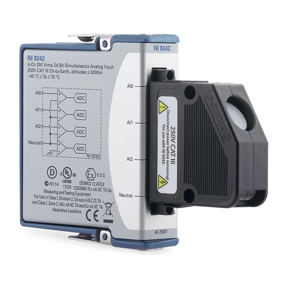
- Page 1 USER MANUAL AND SPECIFICATIONS NI 9242 4-Channel, 250 V , 24-Bit Simultaneous Analog Input Module Français Deutsch ni.com/manuals...
- Page 2 This document describes how to use the National Instruments 9242 and includes specifications and pin assignments for the NI 9242. The safety guidelines and specifications in this Note document are specific to the NI 9242. The other components in the system might not meet the same safety ratings and specifications.
- Page 3 You can compromise the safety protection built into the product if the product is damaged in any way. If the product is damaged, return it to National Instruments for repair. NI 9242 User Manual and Specifications | © National Instruments | 3...
- Page 4 /60 VDC), you must ensure that devices and circuits connected to the module are properly insulated from human contact. You must use the NI 9967 connector backshell kit to ensure that the terminals are not accessible. 4 | ni.com | NI 9242 User Manual and Specifications...
- Page 5 Figure 1 shows the NI 9967 connector backshell. Figure 1. NI 9967 Connector Backshell NI 9242 User Manual and Specifications | © National Instruments | 5...
- Page 6 Safety Guidelines for Hazardous Locations The NI 9242 is suitable for use in Class I, Division 2, Groups A, B, C, D, T4 hazardous locations; Class I, Zone 2, AEx nA IIC T4, and Ex nA IIC T4 hazardous locations; and nonhazardous locations only.
- Page 7 -40 °C ≤ Ta ≤ 70 °C. If you are using the NI 9242 in Gas Group IIC hazardous locations, you must use the device in an NI chassis that has been evaluated as Ex nC IIC T4, EEx nC IIC T4, Ex nA IIC T4, or Ex nL IIC T4 equipment.
- Page 8 Furthermore, any changes or modifications to the product not expressly approved by National Instruments could void your authority to operate it under your local regulatory rules. 8 | ni.com | NI 9242 User Manual and Specifications...
- Page 9 In addition, take precautions when designing, selecting, and installing measurement probes and cables to ensure that the desired EMC performance is attained. NI 9242 User Manual and Specifications | © National Instruments | 9...
- Page 10 Connecting the NI 9242 The NI 9242 provides connections for four analog input channels. Figure 2. NI 9242 Pinout Neutral 10 | ni.com | NI 9242 User Manual and Specifications...
- Page 11 You can use the backshell with 12 AWG to 24 AWG wires with the NI 9967. 12 AWG to 14 AWG, 16 AWG, and 18 AWG to 24 AWG require different strain-relief pieces. NI 9242 User Manual and Specifications | © National Instruments | 11...
- Page 12 14 AWG wires. Figure 3. 12 AWG to 14 AWG Installation 1 Route wires over the strain-relief piece. 2 Secure strain-relief piece and NI 9967 backshell in place using captive screws. 12 | ni.com | NI 9242 User Manual and Specifications...
- Page 13 Complete the following steps to install the NI 9967 using 16 AWG wires. Figure 4. 16 AWG Installation 1 Route wires through the strain-relief pieces. 2 Secure strain-relief piece and NI 9967 backshell in place using captive screws. NI 9242 User Manual and Specifications | © National Instruments | 13...
- Page 14 Complete the following steps to install the NI 9967 using 16 AWG wires. Figure 5. 18 AWG to 24 AWG Installation 1 Route wires over the strain-relief piece. 2 Secure strain-relief piece and NI 9967 backshell in place using captive screws. 14 | ni.com | NI 9242 User Manual and Specifications...
- Page 15 Signals The NI 9242 has three AI terminals and a Neutral terminal. You can connect three-phase and single-phase measurement configurations to the NI 9242. The NI 9242 supports standard service levels up to 250 V Line-to-Neutral (L-N) and 400 V Line-to-Line (L-L).
- Page 16 To ensure that measurements to chassis ground are correct, NI recommends connecting the chassis to earth ground using the chassis grounding screw. Refer to your chassis manual for information about connecting the chassis to earth ground. 16 | ni.com | NI 9242 User Manual and Specifications...
- Page 17 NI recommends using the following phase measurement configurations for typical power distribution networks. Other valid configurations are possible if the connections do not exceed the safety rating of the NI 9242. NI 9242 User Manual and Specifications | © National Instruments | 17...
- Page 18 You can connect WYE or delta measurement configurations to the NI 9242. Figure 7. Connecting a 4-Wire WYE Measurement Configuration Phase A Phase B Phase C Neutral Neutral NI 9242 18 | ni.com | NI 9242 User Manual and Specifications...
- Page 19 Figure 8. Connecting a High-Leg Delta Measurement Configuration Phase A Phase B Phase C Neutral Neutral NI 9242 NI 9242 User Manual and Specifications | © National Instruments | 19...
- Page 20 Figure 9. Connecting a 3-Wire Delta Measurement Configuration Phase A Phase B Phase C NI 9242 20 | ni.com | NI 9242 User Manual and Specifications...
- Page 21 Figure 10. Connecting a Corner Grounded 2-Wire Delta Measurement Configuration Phase A Phase B Phase C NI 9242 Corner grounded 2-wire delta measurement Note configurations support only standard service levels up to 240 V L-L. NI 9242 User Manual and Specifications | © National Instruments | 21...
- Page 22 Connecting Single-Phase Measurement Configurations You can connect 3-wire or 2-wire single-phase measurement configurations to the NI 9242. Figure 11. Connecting a 3-Wire Measurement (Split Phase) Configuration Neutral NI 9242 22 | ni.com | NI 9242 User Manual and Specifications...
- Page 23 For example, if using a 320:1 ratio potential transformer, multiply the readings by 320. NI 9242 User Manual and Specifications | © National Instruments | 23...
- Page 24 Figure 13. 4-Wire WYE-to-WYE (Full) Phase A Phase B Phase C Neutral NI 9242 24 | ni.com | NI 9242 User Manual and Specifications...
- Page 25 Ensure that you scale each NI 9242 channel reading with the corresponding transformer ratio. Figure 14. 4-Wire WYE-to-WYE (Partial) Phase A Phase B Phase C Neutral NI 9242 NI 9242 User Manual and Specifications | © National Instruments | 25...
- Page 26 For 4-wire WYE-to-WYE (partial) configurations, follow these guidelines for the best accuracy results. • Connect the Neutral terminal of the NI 9242 to the isolated ground of the potential transformer to reduce noise between the potential transformer ground and the chassis ground.
- Page 27 Phase C NI 9242 1 Optional You can use the Neutral channel for any other measurement if the measurement does not exceed the Neutral-to-Earth and L-N input range. NI 9242 User Manual and Specifications | © National Instruments | 27...
- Page 28 Figure 16. Delta-to-WYE Phase A Phase B Phase C NI 9242 28 | ni.com | NI 9242 User Manual and Specifications...
- Page 29 Use the L-N voltage measurements the NI 9242 returns as the default value. You can convert L-N voltage measurements to channel-to-earth ground by adding the Neutral terminal measurement to each of the AI channels. NI 9242 User Manual and Specifications | © National Instruments | 29...
- Page 30 Phase A Phase B Phase C NI 9242 You can use the Neutral channel for any other measurement if the measurement does not exceed the Neutral-to-Earth and L-N input range. 30 | ni.com | NI 9242 User Manual and Specifications...
- Page 31 Connect the Neutral terminal of the NI 9242 to the isolated ground of the potential transformer to reduce noise between the potential transformer ground and the chassis ground. NI 9242 User Manual and Specifications | © National Instruments | 31...
- Page 32 • Connect the Neutral terminal of the NI 9242 as close as possible to the isolated ground of the potential transformer. • Use the L-N voltage measurements the NI 9242 returns as the default value. You can convert L-N voltage measurements to channel-to-earth ground by adding the Neutral terminal measurement to each of the AI channels.
- Page 33 Refer to the following equation for an example of converting L-N measurements to L-Earth. Line to Earth = AIx + Neutral where AIx is the analog input channel reading Neutral is the Neutral channel reading NI 9242 User Manual and Specifications | © National Instruments | 33...
- Page 34 Refer to Figure 19 for an illustration of using ferrules. Figure 19. 4-Terminal Detachable Screw-Terminal Connector with Ferrule 34 | ni.com | NI 9242 User Manual and Specifications...
- Page 35 Understanding NI 9242 Filtering The NI 9242 uses a combination of analog and digital filtering to provide an accurate representation of in-band signals while rejecting out-of-band signals. The filters discriminate between signals based on the frequency range, or bandwidth, of the signal.
- Page 36 Therefore, the stopband frequency scales precisely with the data rate. The stopband rejection is the minimum amount of attenuation applied by the filter to all signals with frequencies within the stopband. 36 | ni.com | NI 9242 User Manual and Specifications...
- Page 37 12.8 MHz, but the module also can accept an external master timebase or export its own master timebase. To synchronize the data rate of an NI 9242 with other modules that use master timebases to control sampling, all of the modules must share a single master timebase source.
- Page 38 16.667 kS/s, and so on down to 1.613 kS/s, depending on the value of n. When using an external timebase with a frequency other than 12.8 MHz, the NI 9242 has a different set of data rates. The NI 9151 R Series Expansion chassis does not Note support sharing timebases between modules.
- Page 39 The following specifications are typical for the range -40 °C to 70 °C unless otherwise noted. Input Characteristics Scaling coefficient ......59,605 nV/LSB Number of channels......4 analog input channels NI 9242 User Manual and Specifications | © National Instruments | 39...
- Page 40 , n = 1, 2, …, 31 -------------------- - The data rate must remain within the appropriate data rate range. Refer to the Understanding NI 9242 Data Rates section for more information. 40 | ni.com | NI 9242 User Manual and Specifications...
- Page 41 Calibrated typ (23 °C ±5 °C) 0.05% 0.022% Uncalibrated max (-40 °C to 70 °C) 0.50% 0.26% Uncalibrated typ (23 °C ±5 °C) 0.18% 0.06% Range equals 354 V (250 V × √2) NI 9242 User Manual and Specifications | © National Instruments | 41...
- Page 42 Nonlinearity (at 25 °C) ..... 20 ppm Stability Gain drift ........12.1 ppm/ °C Offset drift ........3.4 mV/ °C The NI 9242 returns L-N and N-Earth values only. Refer to Converting L-N Measurements to L-L Converting L-N Measurements to L-Earth sections for details on changing the point of reference of the measurement.
- Page 43 + 1.5 µs -------- - Passband Frequency ........0.453 * f Flatness 0 kHz to 20 kHz ......±50 mdB max 0 kHz to 10 kHz ......±20 mdB max NI 9242 User Manual and Specifications | © National Instruments | 43...
- Page 44 Zero phase sequence error at 50 Hz and 60 Hz At 5% unbalance Maximum......0.21% Typical........0.09% At 1% unbalance Maximum......0.22% Typical........0.1% Stopband Frequency ........0.547 * f Rejection........-95 dB Alias-free bandwidth ......0.453 * f 44 | ni.com | NI 9242 User Manual and Specifications...
- Page 45 Power consumption from chassis Active mode ....... 332 mW max Sleep mode ......... 50 µW max Thermal dissipation Active mode ....... 582 mW max Sleep mode ......... 250 mW max NI 9242 User Manual and Specifications | © National Instruments | 45...
- Page 46 Torque for screw terminals ....0.5 N · m to 0.6 N · m (4.42 lb · in. to 5.30 lb · in.) Ferrules ..........0.25 mm to 2.5 mm Weight..........150 g (5.3 oz) 46 | ni.com | NI 9242 User Manual and Specifications...
- Page 47 Do not connect the NI 9242 to signals or use Caution for measurements within Measurement Categories IV. NI 9242 User Manual and Specifications | © National Instruments | 47...
- Page 48 • IEC 61010-1, EN 61010-1 • UL 61010-1, CSA 61010-1 • EN 60079-0:2009, EN 60079-15:2010 • IEC 60079-0:2007; Ed 5, IEC 60079-15:2010; Ed 4 48 | ni.com | NI 9242 User Manual and Specifications...
- Page 49 AS/NZS CISPR 11: Group 1, Class A emissions • AS/NZS CISPR 22: Class A emissions • FCC 47 CFR Part 15B: Class A emissions • ICES-001: Class A emissions NI 9242 User Manual and Specifications | © National Instruments | 49...
- Page 50 Note Online Product Certification section. CE Compliance This product meets the essential requirements of applicable European Directives as follows: • 2006/95/EC; Low-Voltage Directive (safety) • 2004/108/EC; Electromagnetic Compatibility Directive (EMC) 50 | ni.com | NI 9242 User Manual and Specifications...
- Page 51 Certification column. Shock and Vibration To meet these specifications, you must panel mount the system. If you are using the NI 9242 with screw terminal, you also must either affix ferrules to the ends of the terminal wires. Operating vibration Random (IEC 60068-2-64)..
- Page 52 Ingress protection......IP 40 Operating humidity (IEC 60068-2-56)......10% to 90% RH, noncondensing Storage humidity (IEC 60068-2-56)......5% to 95% RH, noncondensing Pollution Degree ....... 2 Maximum altitude......5,000 m Indoor use only. 52 | ni.com | NI 9242 User Manual and Specifications...
- Page 53 WEEE recycling center. For more information about WEEE recycling centers, National Instruments WEEE initiatives, and compliance with WEEE Directive 2002/96/EC on Waste and Electronic Equipment, visit ni.com/environment/ weee NI 9242 User Manual and Specifications | © National Instruments | 53...
- Page 54 NI Application Engineers. Visit for NI Factory Installation Services, ni.com/services repairs, extended warranty, and other services. 54 | ni.com | NI 9242 User Manual and Specifications...
- Page 55 United States, visit the Worldwide Offices section of to access the branch office ni.com/niglobal websites, which provide up-to-date contact information, support phone numbers, email addresses, and current events. NI 9242 User Manual and Specifications | © National Instruments | 55...
- Page 56 For patents covering National Instruments products/technology, refer to the appropriate location: Help»Patents in your software, the patents.txt file on your media, or the National Instruments Patent Notice at ni.com/patents . You can find end-user license agreements (EULAs) and third-party legal notices in the readme file for your NI product.
Need help?
Do you have a question about the NI 9242 and is the answer not in the manual?
Questions and answers