
Related Manuals for National Instruments NI 9210


Summary of Contents for National Instruments NI 9210
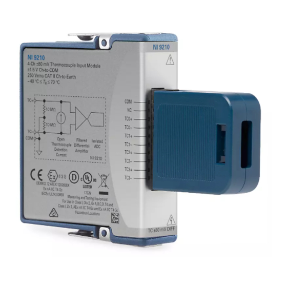
- Page 1 GETTING STARTED GUIDE NI 9210 4-Channel, 14 S/s Aggregate, ±80 mV C Series Temperature Input Module...
-
Page 2: Safety Guidelines
This document explains how to connect to the NI 9210. In this document, the NI 9210 with mini-TC and the NI 9210 with spring terminal are referred to inclusively as the NI 9210. Before you begin, complete the software and... -
Page 3: Ni 9210 With Mini-Tc Safety Voltages
Connect only voltages that are within the following limits: Isolation Channel-to-channel None Channel-to-earth ground Continuous 60 V DC, Measurement Category I Withstand 1,000 V RMS, verified by a 5 s dielectric withstand test NI 9210 Getting Started Guide | © National Instruments | 3... - Page 4 Such voltage measurements include signal levels, special equipment, limited-energy parts of equipment, circuits powered by regulated low-voltage sources, and electronics. Do not connect the NI 9210 with mini-TC to Caution signals or use for measurements within Measurement Categories II, III, or IV.
-
Page 5: Ni 9210 With Spring Terminal Safety Voltages
115 V for U.S. or 230 V for Europe. Do not connect the NI 9210 with spring Caution terminal to signals or use for measurements within Measurement Categories III or IV. NI 9210 Getting Started Guide | © National Instruments | 5... -
Page 6: Safety Guidelines For Hazardous Locations
Safety Guidelines for Hazardous Locations The NI 9210 is suitable for use in Class I, Division 2, Groups A, B, C, D, T4 hazardous locations; Class I, Zone 2, AEx nA IIC T4 Gc and Ex nA IIC T4 Gc hazardous locations; and nonhazardous locations only. -
Page 7: Special Conditions For Hazardous Locations Use In Europe And Internationally
II 3G and is suitable for use in Zone 2 hazardous locations, in ambient temperatures of -40 °C ≤ Ta ≤ 70 °C. If you are using the NI 9210 in Gas Group IIC hazardous locations, you must use the device in an NI chassis that has been evaluated as Ex nC IIC T4, Ex IIC T4, Ex nA IIC T4, or Ex nL IIC T4 equipment. -
Page 8: Electromagnetic Compatibility Guidelines
To minimize interference with radio and television reception and prevent unacceptable performance degradation, install and use this product in strict accordance with the instructions in the product documentation. 8 | ni.com | NI 9210 Getting Started Guide... -
Page 9: Special Conditions For Marine Applications
LR certificate, or look for the Lloyd’s Register mark on the product. In order to meet the EMC requirements for Caution marine applications, install the product in a shielded NI 9210 Getting Started Guide | © National Instruments | 9... -
Page 10: Preparing The Environment
EMC performance is attained. Preparing the Environment Ensure that the environment in which you are using the NI 9210 meets the following specifications. Operating temperature -40 °C to 70 °C... -
Page 11: Ni 9210 With Mini Tc Pinout
NI 9210 with Mini TC Pinout NI 9210 Getting Started Guide | © National Instruments | 11... - Page 12 Table 1. Signal Descriptions Signal Description Common reference connection to isolated ground Thermocouple connection 12 | ni.com | NI 9210 Getting Started Guide...
-
Page 13: Ni 9210 With Spring Terminal Pinout
NI 9210 with Spring Terminal Pinout TC0+ TC0– TC1+ TC1– TC2+ TC2– TC3+ TC3– NI 9210 Getting Started Guide | © National Instruments | 13... -
Page 14: Thermocouple Connections
Connect the COM terminal to a common-mode voltage reference on the thermocouple. A valid common-mode voltage reference is a voltage that is within ±1.5 V of the common-mode voltage of all the connected thermocouples 14 | ni.com | NI 9210 Getting Started Guide... -
Page 15: Minimizing Thermal Gradients
Keep the NI 9210 in a stable and consistent orientation. • Allow the thermal gradients to settle after a change in system power or in ambient temperature. A change in system power NI 9210 Getting Started Guide | © National Instruments | 15... -
Page 16: Ni 9210 Connection Guidelines
Make sure that devices you connect to the NI 9210 are compatible with the module specifications. • For the NI 9210 with spring terminal, push the wire into the terminal when using a solid wire or a stranded wire with a ferrule. -
Page 17: Ni 9210 With Mini Tc Com Connection Guidelines
Overvoltage Protection The NI 9210 provides overvoltage protection for each channel. Refer to the device datasheet on ni.com/manuals Note for more information about overvoltage protection. NI 9210 Getting Started Guide | © National Instruments | 17... -
Page 18: Where To Go Next
NI 9210 Datasheet NI 9210 Datasheet NI-RIO Help NI-DAQmx Help LabVIEW FPGA Help LabVIEW Help RELATED INFORMATION C Series Documentation Services & Resources ni.com/services ni.com/info cseriesdoc Located at ni.com/manuals Installs with the software 18 | ni.com | NI 9210 Getting Started Guide... -
Page 19: Worldwide Support And Services
You can obtain the DoC for your product by visiting ni.com/certification. If your product supports calibration, you can obtain the calibration certificate for your product at ni.com/calibration. NI 9210 Getting Started Guide | © National Instruments | 19... - Page 20 For patents covering NI products/technology, refer to the appropriate location: Help»Patents in your software, file on your media, or the National Instruments Patent Notice at patents.txt ni.com/ . You can find information about end-user license agreements (EULAs) and third-party patents legal notices in the readme file for your NI product.
Need help?
Do you have a question about the NI 9210 and is the answer not in the manual?
Questions and answers