
Related Manuals for VEVOR LB175A


Summary of Contents for VEVOR LB175A
- Page 1 Customer Support Monday-Friday:9:00am-17:00pm Mail:vevorkitchen18888 @outlook .com You can contact us when you meet any problems, we will serve you with all our heart. Your satisfaction is our priority! More about Our Ice Maker...
-
Page 2: Table Of Contents
Water supply/Purge --------------- -------5 6.1 Water Supply ------ ---------------- -------5 The manual covers the following Purge ---------------- --------- -----------5 LB175A,LB210A,LB300A ---------------- 7. Power supply ------- ----------6 Sanitation after Installation-------------- Check after Installation ---------------- ---6 --------------- 10. Operation ------------- ---------7 11. Working process------------ ------------------ 12. - Page 3 Safety Tips Safety Tips When operates and maintains an ice maker ,be sure to pay attention to the safety tips in the manual. Ignoring these tips may result in personal injury and ice maker damage. In this manual, you will see the following forms of security tips: Warning Possible personal injury would be happened when not following up regulations of installation, operation or using altered equipment.
-
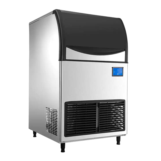
Page 4: Features
1 ... ice maker door 2. Decorative panel 3. Ventilation windows ④. Top cover plate 5. Display screen 6. Right panel ⑦. Adjust the base foot Ice maker size list (in cm) LB175A 66.5 84.5 72.5 . ⑧. Backplane 9 drain hole 10. Water intake LB210A 66.5... -
Page 5: Unpack
Safety Tips Water supply/Purge Do not block the ventilation window of the ice 3. Unpack maker. There should be enough air Before unpacking, check whether the anti-tilt convection space around the ice maker; mark (if any) is in good condition, whether the The ice maker can not work at sub-zero ... -
Page 6: Water Supply
Safety Tips Water supply/Purge Drain hose should be wrapped with insulation material to prevent 6. Water supply/ Purge condensation. The drain hose of the water-cool condenser and the drain hose of ice Warning bin should be placed separately Ice makers shall be installed in About 2.5 centimeters drop needed ... -
Page 7: Power Supply
Safety Tips Power supply 7. Power supply The voltage, frequency and capacity of 9. Check after Installation the power supply shall be consistent with the nameplate of the machine. After the ice maker is installed, check ±10% fluctuation of rated power voltage ... -
Page 8: Operation
Safety Tips Ice Maker Operation ice; when the ice is removed, the ice machine 10. Operation begins to make ice; b. in standby state, press "once, start making "boot/ shutdown " : mode ice. ▲ attention " ": Booking / Plus: Lighting / Subtraction ": Clean/set "... - Page 9 Safety Tips Ice Maker Operation after drainage, enter automatic rinsing stage, Clean for 3 minutes, drain for 30 s, and recyclefor 5 times. The cleaning process ends and the screen shows OFF", enter standby state; Note: if you need quick cleaning, you can not wait 15 minutes to start drainage directly after 30 s, enter the rinsing stage, rinse if you do not need to cycle many times can press...
-
Page 10: Working Process
Safety Tips Working Process turn to ice full. Three times in a row for more than 11. Working process 6 minutes, turn to deicing timeout stop. 11.1. Ice melting process: the display screen is 11.4. Ice full detection: after the ice is removed, if fully bright after power on and completely the ice in the refrigerator is not full, enter the ice extinguished after 1 second.Display C00 indicates... -
Page 11: Routine Cleaning
Safety Tips Check before operation ★ important 13. Routine cleaning If necessary, it is not recommended to remove the top cover plate, please have the relevant ▲ attention knowledge or under the guidance of It is strictly forbidden to wash the ice ... -
Page 12: Evaporator Cleaning
Safety Tips Cleaning and Disinfection the clamps, unplug the upper water pipe, pump and float plug-in to remove the pump and float clean; 13.2. Evaporator cleaning Scrub the evaporator surface with a brush or sponge dipped in scale remover or vinegar; Use soft ground materials such as brush or Use nylon brush to dip in scale remover or sponge to dip in scale remover or vinegar to... -
Page 13: Cleaning Of Condenser
Safety Tips Cleaning and disinfection 13.4 Condenser cleaning Warning Clean condenser, must disconnect ice Pull up the filter on the ventilation machine power supply. Condenser edge sharp, clean carefully cut. ▲ attention window It is strictly forbidden to wash the ice ... -
Page 14: Cleaning & Disinfection
Safety Tips Cleaning and disinfection deicing program (see "10.4 forced deicing "above) so that the ice maker stops making 14. Cleaning and disinfection ice, press the" key "in standby state, In order to make the operation of ice maker and the screen displays" OFF";" on the screen stable and efficient, the user has the responsibility to operate according to the requirements of cleaning and disinfection (cleaning and... - Page 15 Safety Tips Cleaning and disinfection Soak the parts in the cleaning solution for more than 5 minutes (if the scale is heavy, it is recommended to soak for more than 10 minutes). 30 s after completion of drainage; While soaking parts, wipe the surface of parts in contact with water and ice with nylon brush or soft cloth dipping cleaning liquid, such as Enter the automatic rinsing phase, clean for 3...
-
Page 16: Disinfection Process
Safety Tips Cleaning and disinfection Brush pipe mandrel Brush pump bottom Plastic parts around brush steam Flush hose and mandrel Remove the soaked parts and rinse them with clean water (5 times). 14.2 Disinfection process The 1. is mixed with 8 liters of warm water Brush evaporator (45~50℃) and 2 packets of disinfectant (KAY5,28.4/ package) to form disinfectant (the... -
Page 17: Removal / Installation Of Parts
Safety Tips Cleaning and disinfection drainage begins and the evaporator is flushed After 20 minutes, remove the soaked parts and 30 s after completion of drainage; rinse with water Wash the sterilized parts.Parts to be removed Installed in situ with reference to 14.3 parts removed In addition to / installation process) strictly follow the requirements of this step. - Page 18 Safety Tips Cleaning and disinfection Note: when the pipe is assembled, the pipe hole position and mandrel hole position direction should be opposite, must not be the same direction, the correct diagram is as Unplug pipe follows: b.Remove two screws c....
-
Page 19: Out Of Use/Winterization
Safety Tips Maintenance 16. Maintenance 15. Out of use/Winterization Before applying for repair, please consider the Note following aspects in order to quickly identify and If water is left in the machine in an environment below 0°C, it may cause serious improve the efficiency of machine recovery. -
Page 20: Circuit Diagram
Safety Tips Circuit diagram 17. Circuit diagram Number: JT190199990 Version Number: A1 Note: Subsequent versions of this specification are subject to change without prior notice. Thank you 19/23... -
Page 21: Exploded Drawing
Safety Tips Assembly system 18. Explosive maps Assembly system Serial number Figure 1 LB175A LB210A LB300A Backward back panel Rear vertical bracket A of inner guard Left panel Floor Machine foot Front vertical bracket Windscreen B of inner guard Filter... - Page 22 Safety Tips Refrigeration system Refrigeration system Serial number Figure 1 LB175A LB210A LB300A Solenoid valve Compressor Condenser Number: JT190199990 Version Number: A1 Note: Subsequent versions of this specification are subject to change without prior notice. Thank you 21/23...
- Page 23 Safety Tips Water circulation system Water circulation system Serial number Figure 1 LB175A LB210A LB300A Ice storage tanks Water intake valve Drainage Water intake Feed pipe joints Pump Water mains Flats Flow pipe Number: JT190199990 Version Number: A1 Note: Subsequent versions of this specification are subject to change without prior notice. Thank you...
- Page 24 Safety Tips Electric control system Electric control system Serial number Figure 1 LB175A LB210A LB300A Compressor Water intake valve Pump solenoid valve coil Power switch Circuit Board Display Number: JT190199990 Version Number: A1 Note: Subsequent versions of this specification are subject to change without prior notice. Thank you...
Need help?
Do you have a question about the LB175A and is the answer not in the manual?
Questions and answers
I need a part number on a board to order a new one