Table of Contents
Advertisement
Quick Links
[1]
Safety Precaution For Service Manual ..........1-1
[2]
Important Service Notes (for U.K. only)......... 1-1
[3]
Specifications ................................................1-1
[4]
Name Of Parts............................................... 1-2
[1]
Disassembly .................................................. 2-1
[1]
Function Table Of IC...................................... 3-1
[1]
Voltage .......................................................... 4-1
!
Parts marked with "
" are important for maintaining the safety of the set. Be sure to replace these parts with
specified ones for maintaining the safety and performance of the set.
SHARP CORPORATION
SERVICE MANUAL
MODEL
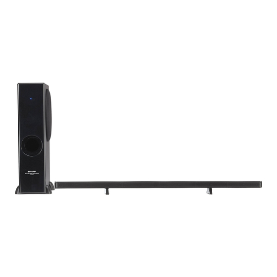
HT-SL50 Sound Bar Home Theater system consisting of
Sound Bar and Subwoofer.
• In the interests of user-safety the set should be restored to its
original condition and only parts identical to those specified
be used.
CONTENTS
CHAPTER 5. DIAGRAM
[1]
Block Diagram................................................5-1
LAYOUT
[1]
Notes On Schematic Diagram .......................6-1
[2]
Types Of Transistor And LED.........................6-1
[3]
Schematic Diagram................................ . ........6-2
[4]
Chart Of Connecting Wires.................... . ........6-8
[5]
Wiring Side Of PWB .............................. . ........6-9
This document has been published to be used
for after sales service only.
The contents are subject to change without notice.
No. S4107HTSL50HE
SOUND BAR HOME
THEATER SYSTEM
HT-SL50
HT-SL50
Advertisement
Table of Contents

Related Manuals for Sharp HT-SL50


Summary of Contents for Sharp HT-SL50
-
Page 1: Table Of Contents
SOUND BAR HOME THEATER SYSTEM HT-SL50 MODEL HT-SL50 Sound Bar Home Theater system consisting of Sound Bar and Subwoofer. • In the interests of user-safety the set should be restored to its original condition and only parts identical to those specified be used. -
Page 2: Precautions For Using Lead-Free Solder
HT-SL50 PRECAUTIONS FOR USING LEAD-FREE SOLDER 1. Employing lead-free solder "MAIN, SMPS, HDMI PWB" of this model employs lead-free solder. The LF symbol indicates lead-free solder, and is attached on the PWB and service manuals. The alphabetical character following LF shows the type of lead-free solder. -
Page 3: Chapter 1. General Description
HT-SL50 CHAPTER 1: GENERAL DESCRIPTION [1] Safety Precaution For Service Manual WARNING This unit contains no user serviceable parts. Never remove covers unless qualified to do so. This unit contains dangerous voltages, always remove mains plug from the socket before any service operation and when not in use for a long period. - Page 4 HT-SL50 [4] Names Of Parts FRONT VIEW REAR VIEW Sound Bar 1. Left Front Speaker 2. Right Front speaker 3. Bass Reflex Duct 4. Right Front Speaker terminal (Red/Black) 5. Left Front Speaker terminal (White/Black) FRONT VIEW REAR VIEW ACTIVE SUBWOOFER SYSTEM...
-
Page 5: Chapter 2. Mechanism Description
HT-SL50 CD-ES700/CD-ES77 CD-ES700/CD-ES77 Service Manual CD-ES700/CD-ES77 Market CHAPTER 2. MECHANISM DESCRIPTION [1] Disassembly Caution On Disassembly Follow the below-mentioned notes when disassembling the unit and reassembling it, to keep it safe and ensure excellent performance: 1. Be sure to remove the power supply plug from the wall outlet before starting to disassemble the unit. -
Page 6: Chapter 3. Major Part Drawing
HT-SL50 CHAPTER 3. MAJOR PART DRAWING [1] Function Table Of IC IC501 RH-IXA308AW00 : System Microcomputer (IXA308AW) (1/3) NAME INPUT / SOFT FORM FUNCTION OUTLINE OUTPUT PULL-UP PORT_TYPE CMOS INPUT/ OUTPUT I2C SERIAL CLOCK BUS LINE OUTPUT P3_5 / SCL / SSCK / (TRCIOD) - Page 7 HT-SL50 IC501 RH-IXA308AW00 : System Microcomputer (IXA308AW) (2/3) NAME INPUT / SOFT FORM FUNCTION OUTLINE OUTPUT PULL-UP PORT_TYPE LED RED CMOS INPUT/ LED indicator. OUTPUT OUTPUT STANDBY condition: H P0_5 / AN2 / CLK1 LED BLUE CMOS INPUT/ LED indicator.
- Page 8 HT-SL50 IC501 RH-IXA308AWZZ : System Microcomputer (IXA308AW) (3/3) DIR_CKSEL P3_4 / TRAO / SSO / RXD1 / (TXD1) DAP_RST P3_3 / INT3 / SSI / TRCCLK RESET RESET P1_0 / KI0 / AN8 DAP_PWN NO USE DAP_MUTE VSS / AVSS...
-
Page 9: Chapter 4. Circuit Description
HT-SL50 CHAPTER 4. CIRCUIT DESCRIPTION [1] Voltage 1. Main PWB IC301 IC501 IC502 CN500 VOLTAGE VOLTAGE VOLTAGE VOLTAGE 10.500m 73.000m 1.490 220.000m -0.000m 140.000m 1.440 -343.000m 0.405 154.000m 1.430 226.000m 2.400m 3.010 0.000m 139.000m 0.200m 0.000m 1.490 22.000m 93.900m 3.000 1.490... - Page 10 HT-SL50 IC901 VOLTAGE VOLTAGE VOLTAGE VOLTAGE 0.460 0.610 0.450 260.000m 2.270 0.610 265.000m 376.000m 0.000m 0.000m 0.000m 32.200m 0.000m 0.000m 242.000m 0.000m 2.280 0.000m 333.000m 0.000m 0.100m 38.800m 187.000m 175.000m 37.600m 0.000m 0.000m 375.000m 0.100m 3.314 0.000m 286.000m 0.000m 3.024 188.000m...
- Page 11 HT-SL50 VOLTAGE VOLTAGE VOLTAGE VOLTAGE -2.920 -3.022 -0.100m -1.223 -0.000m -0.100m -0.849 -200.000m -0.900m -3.021 -2.194 -0.100m -0.000m -3.023 -0.100m -0.200m 69.400m -0.000m -0.752 -0.300m -353.000m -0.000m -0.818 -3.900m -0.750 -0.000m -0.632 -0.000m -1.230 -0.000m -0.758 -0.300m -2.990 -0.000m -10.440m -0.700m...
-
Page 12: Block Diagram
HT-SL50 CHAPTER 5. DIAGRAMS [1] Block Diagram TO/FROM MICOM HDMI RST HDMI INT MICOM FLASH FROM SUBWOOFER BOX CN500 +1.8V +3.3V UNSW IC901 STA5342L BICOLOR LED HDMI PWB CN700 Y2 (24MHZ) Y3 (18.432MHZ) +12V Under- C I 3 HDMI IN... -
Page 13: Chapter 6. Circuit Schematics And Parts
HT-SL50 CHAPTER 6. CIRCUIT SCHEMATICS AND PARTS LAYOUT [1] Notes On Schematic Diagram Resistor: • • Schematic diagram and Wiring Side of P.W.Board To differentiate the units of resistors, such symbol as this model subject change K and M are used: the symbol K means 1000 ohm improvement without prior notice. -
Page 14: Schematic Diagram
HT-SL50 [3] Schematic Diagram MAIN PWB-A MICOM REFLASH AUDIO SIGNAL HDMI SECTION ONLY B711AW +28.4V L922 +28.4V R995 GND1 Figure 6-1: MAIN SCHEMATIC DIAGRAM 6 – 2... - Page 15 HT-SL50 TX_AVDD33 TX_VDD18 TX_VDD18 VDD18 C502 0.1u C500 C501 C503 0.1u 0.1u 0.1u ] 5 [ HDMI PWB-C EP91A1K_RSTb TX_VDD18 B100 C528 15p C504 201209-300 C505 0.1u R513 VDDE 18.432M TX_VDD18 C527 C526 15p R522 0.1u R512 SPDIF IICA R511...
- Page 16 HT-SL50 HDMI PWB-C M33D M33D CLOSE TO PAD MCU Section CLK24M1 C77> C78> 24MHz 24MHz 0.1u 0.1u 0.1u 0.1u R137 EPF021A_P62 EPF021A_P63 CECRX_PRG M33D R142 R143 R144 R145 CEC_RSTb M33D R700 M33D M33D M33D M33D 0.1u R100 M33D R141 R140...
-
Page 17: Chart Of Connecting Wires
HT-SL50 [4] Chart Of Connectng Wires SPEAKER SYSTEM EXTERNAL MICOM LINE INPUT REFLASH ONLY HDMI OUT HDMI IN FIRMWARE FLASH TV ARC ONLY CN500 SUBWOOFER CNS301 HDMI PWB-C BICOLOR LED CNS700 Bi801 Bi800 CON1 CNS800 SMPS PWB-B AC POWER SUPPLY CORD... -
Page 18: Wiring Side Of Pwb
HT-SL50 [5] Wiring Side Of PWB MAIN PWB-A 5 4 3 2 1 3 4 5 6 7 8 9 1 0 TOP VIEW BOTTOM VIEW Lead-free solder indication Lead-free solder is used in the MAIN PWB. Refer to "Precautions for handling lead-free solder" for instructions and precautions. - Page 19 HT-SL50 HDMI PWB-C TOP VIEW BOTTOM VIEW Lead-free solder indication Lead-free solder is used in the HDMI PWB. Refer to "Precautions for handling lead-free solder" for instructions and precautions. Figure 6-6: WIRING SIDE OF HDMI PWB 6 – 7...
- Page 20 HT-SL50 -MEMO- 6 – 8...
-
Page 21: Parts Guide
HT-SL50 PARTS GUIDE SOUND BAR HOME THEATER SYSTEM HT-SL50 MODEL HT-SL50 Sound Bar Home Theater system consisting of Sound Bar and Subwoofer. CONTENTS RESISTORS INTEGRATED CIRCUITS OTHER CIRCUITRY PARTS TRANSISTORS CABINET PARTS / DIODES SUBWOOFER PARTS COILS [10] ACCESSORIES / PACKING PARTS CRYSTALS / VIBRATORS [11] P.W.B. - Page 22 HT-SL50 PRICE PART PARTS CODE DESCRIPTION RANK MARK RANK [1] INTEGRATED CIRCUITS VHiEP91H0++-1 HDMI 1.4 Audio Return Channel Transceiver VHiEPF011C+-1 Generic MCU with 64K Embedded Flash RH-IXA310AW00 HDMI iC VHiEP91A1K+-1 HDMI 1.3 1 Out Repeater with Audio Output iC301 VHiPCM1808P-1...
- Page 23 HT-SL50 PRICE PART PARTS CODE DESCRIPTION RANK MARK RANK [6] CAPACITORS RC-KZ3035AWZZ 47 µF,10V,Electrolytic VCKYCY1HB104K 0.1 µF,50V VCKYCY1HB104K 0.1 µF,50V RC-KZA110WJZZ 10 µF,25V VCKYCY1HB104K 0.1 µF,50V VCKYCY1EB105K 1 µF,50V VCKYCY1HB104K 0.1 µF,50V VCCCCY1HH330J 33 pF (CH),50V VCKYCY1HB104K 0.1 µF,50V VCKYCY1HB104K 0.1 µF,50V...
- Page 24 HT-SL50 PRICE PART PARTS CODE DESCRIPTION RANK MARK RANK [6] CAPACITORS C621 VCTYPA1HF104Z 0.1 µF,50V C622 VCKYPA1HB222K 2200 pF,50V C624 VCCCCZ1HH390J 39 pF,50V C625 VCCCCZ1HH390J 39 pF,50V C633 VCKYCZ1EB104K 0.1 µF,25V C636 VCKYCZ1EB104K 0.1 µF,25V C648 VCKYCZ1EB104K 0.1 µF,25V C653 VCKYCZ1EB104K 0.1 µF,25V...
- Page 25 HT-SL50 PRICE PART PARTS CODE DESCRIPTION RANK MARK RANK [7] RESISTORS VRS-CY1JB000J 0 ohms,Jumper,0.8X1.55mm VRS-CY1JB000J 0 ohms,Jumper,0.8X1.55mm VRS-CY1JB000J 0 ohms,Jumper,0.8X1.55mm VRS-CY1JB000J 0 ohms,Jumper,0.8X1.55mm VRS-CY1JB000J 0 ohms,Jumper,0.8X1.55mm VRS-CY1JB103F 10 kohm,1/16W VRS-CY1JB103F 10 kohm,1/16W VRS-CY1JB103F 10 kohm,1/16W VRS-CY1JB560J 56 ohm,1/16W VRS-CY1JB273F 27 kohm,1/16W...
- Page 26 HT-SL50 PRICE PART PARTS CODE DESCRIPTION RANK MARK RANK [7] RESISTORS R514 VRS-CZ1JB102J 1 kohm,1/16W [Use in MAIN PWB-A] R515 VRS-CZ1JB102J 1 kohm,1/16W [Use in MAIN PWB-A] R515 VRS-CY1JB103F 10 kohm,1/16W [Use in HDMI PWB-C] R516 VRS-CZ1JB102J 1 kohm,1/16W [Use in MAIN PWB-A]...
- Page 27 HT-SL50 PRICE PART PARTS CODE DESCRIPTION RANK MARK RANK [7] RESISTORS R982 VRS-CZ1JF3R3J 3.3 ohm,1/16W R983 VRS-CZ1JF3R3J 3.3 ohm,1/16W R984 VRS-CZ1JF3R3J 3.3 ohm,1/16W R985 VRS-CZ1JF3R3J 3.3 ohm,1/16W R990 VRS-CY1JB103J 10 kohm,1/16W R991 VRS-CY1JB103J 10 kohm,1/16W R992 VRS-CY1JB103J 10 kohm,1/16W R993...
- Page 28 HT-SL50 [9] CABINET PARTS / SUBWOOFER PARTS 603 x 2 608 x 4 605 x 4 607 x 4 PWB-A 602 x 2 FROM HDMI PWB 601 x 3 205 x 2 FROM HDMI 606 x 2 PWB-B 601 x 4...
- Page 29 HT-SL50 PRICE PART PARTS CODE DESCRIPTION RANK MARK RANK [9] CABINET PARTS / SUBWOOFER PARTS GiTARA822AWSA Rear Panel LANGT0042AWFW Bracket, PWB Support LBSHC0002AWZZ Bushing, AC Power Supply Cord LCHSMA110AWFW Chassis, Main PCUSGA182AWZZ Cushion, Heat Sink PRDARA224AWFW Heat Sink, IC QACCBA008AW00 AC Power Supply Cord [ For U.K.
- Page 30 HT-SL50 [10] CABINET PARTS / SUBWOOFER PACKING METHOD (FOR U.S.A ONLY) 1 Sound Bar Ass'y B3CPSB50//2 11 Packing Add, Top SPAKAA311AWZZ 2 Subwoofer Stand Ass'y GiTAUA004AW01 12 Packing Add, Bottom SPAKAA312AWZZ 3 Sound Bar Stand GITAUA012AWSB 13 Packing Case SPAKCA864AWZZ...
- Page 31 HT-SL50 -MEMO-...
- Page 32 HT-SL50 COPYRIGHT 2011 BY SHARP CORPORATION ALL RIGHTS RESERVED. No part of this publication may be reproduced, stored in a retrieval system, or transmitted in any form or by any means, electronic, mechanical, photocopying, recording, or otherwise, without prior written permission of the publisher.
- Page 33 The sound bar is unable to decode the audio. ACTION You need examine the connected equipment and change the Digital Audio Output from Bitstream to PCM. Sharp Electronics (UK) Limited Reference – RG16012012 Revision - 1 White – Carry out as required Yellow –...
- Page 34 IC 501 Main CPU RH-iXA326AW00 Sound Bar Ass'y, B3CPSB50N/2 Sharp Electronics (UK) Limited Reference – TSI 11X0004 Revision - 1 White – Carry out as required Yellow – Carry out as required and whenever the unit comes in for service...
- Page 35 HT-SL70 only, C622 removal. 1. Remove the 4 screw at the back of the unit. 2. Remove the 5 x bottom screws as shown above Sharp Electronics (UK) Limited Reference – RG20120119 Revision - 1 White – Carry out as required Yellow –...
- Page 36 3. Cut Cable Tie to enable easier removal of Chassis. 4. Locate C622 and remove ( Green Disc capacitor ). 5. Re-address cable, fit new cable tie, relocate the chassis and refit screws. Sharp Electronics (UK) Limited Reference – RG20120119 Revision - 1 White –...
- Page 37 2. Connect the Software writer jig as shown below. Figure 1. Jig Red light should be iluminated. 3. Press the RH tip button. Figure 2. R.H. Button press to start programming cycle. Sharp Electronics (UK) Limited Reference – RG20120119 Revision - 1 White – Carry out as required Yellow –...
- Page 38 4. Yellow light should iluminate to show unit in programming mode 5. When operation is completed Blue light will iluminate. 6. When completed un-plug the mains supply Leave programming jig in place . Sharp Electronics (UK) Limited Reference – RG20120119 Revision - 1 White –...
- Page 39 8. Ensure the Red Light is ON if not adjust switch J3. 9. Turn OFF the Mains supply. 10. Start PC program (EPFlash) program installed on the PC. Sharp Electronics (UK) Limited Reference – RG20120119 Revision - 1 White – Carry out as required Yellow –...
- Page 40 13. When reprograming is completed the message “ Write Block ( 0 – 155 ) OK” will be displayed as below 14. Unplug the Mains supply and remove programming tools and check funtionality to ensure all is OK. Sharp Electronics (UK) Limited Reference – RG20120119 Revision - 1 White – Carry out as required Yellow –...