Table of Contents
Advertisement
Quick Links
ORDER NO. EMID0103013C0
A4
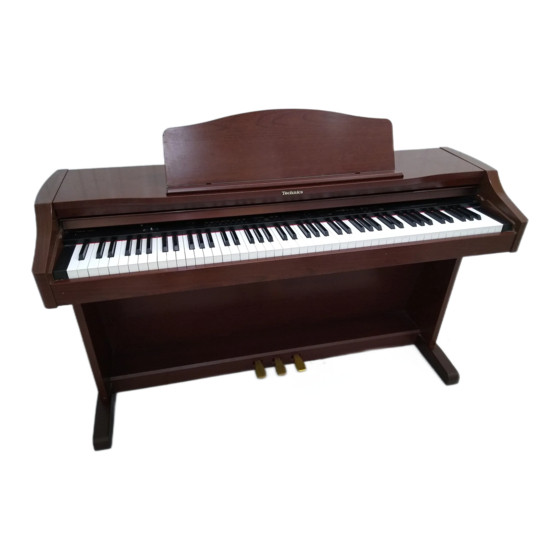
Digital Piano
SX-PX662
Colours
(K) ...................Black
(M) ...................Walnut
Areas
(P) U.S.A., Mexico
(PC) Canada
(EX) Norway, Sweden, Denmark, Finland, Spain, Portugal, Greece,
Poland, Czeco,South Africa
(EG) Switzerland, France, Austria, Holland, Belgium, Italy
(EQ) Germany
(EB) the United Kingdom
(GW) Argentina
(GH) Hong Kong, Saudi Arabia, Kuwait
(GT) Taiwan
(GM) Malaysia, Singapore
(GU) Thailand, Panama, Philippines
(GW) Argentina
(GN) Australia, New Zealand
1
Advertisement
Table of Contents

Related Manuals for Technics SX-PX662


Summary of Contents for Technics SX-PX662
- Page 1 ORDER NO. EMID0103013C0 Digital Piano SX-PX662 Colours (K) ....Black (M) ....Walnut Areas (P) U.S.A., Mexico (PC) Canada (EX) Norway, Sweden, Denmark, Finland, Spain, Portugal, Greece, Poland, Czeco,South Africa (EG) Switzerland, France, Austria, Holland, Belgium, Italy (EQ) Germany (EB) the United Kingdom...
-
Page 2: Specifications
SPECIFICATIONS SPECIFICATIONS KEYBOARD 88 KEYS MAX. POLYPHONY 64 NOTES SOUND 8 SOUNDS : GRAND, UPRIGHT, E PIANO 1, E PIANO 2, HARPSI, VIBES, STRINGS, PIPE ORGAN PEDAL SOFT, SOSTENUTO, SUSTAIN DIGITAL EFFECT BRILLIANCE MELLOW, BRIGHT (5 STEPS) DIGITAL REVERB O (ROOM, STAGE, HALL, CONCERT) TOUCH SENSITIVITY LIGHT, NORMAL, HEAVY... - Page 3 POWER REQUIREMENT 100W 110W (NORTH AMERICA AND MEXICO) AC120/ 220/ 230-240V 50/ 60Hz AC120V 60Hz (NORTH AMERICA AND MEXICO) AC230-240V 50/ 60Hz (EUROPE, AUSTRALIA, ANDNEW ZEALAND) DIMENSIONES (W×H×D) 140.4cm×102.5cm×48.1cm (55-9/32”×40-11/32”×18-15/16”) NET WEIGHT 46kg (101.4lbs) ACCESSORIES AC CORD, MUSIC STAND 1. Warning To prevent the risk of fire, smoke, or electrical shock and to ensure safe operation, please be sure to follow the safety guidelines below.
-
Page 4: Safety Precaution
the unfinished or rough edge of a part. 7. When replacing the power cord (except for the plug-in type), tug it from various directions to confirm that it does not slip out of place. 8. Spacing If soldering was done on the AC primary circuit, confirm that the interval between the soldered terminals or between the terminal and surrounding metallic parts is at least the minimum required (between the primary circuit and the chassis: atleast 6.5 mm;... - Page 5 allexposed parts. (refer to Fig. 1 Fig. 1 3. How to Assemble the Piano 4. Sounds and Effects 5. Initial Setting The following procedure resets all programmable settings, functions and memories to their initialized (factory-preset) status. Use this procedure if the buttons, keys, etc. malfunction, or when you wish to reset the memories and functions.
- Page 6 7. Connections 8. Symptom which Apper to be Signs of Trouble 9. Parts Location 10. Disassembly Instructions 10.1. Removing the top cover and the keyboard cover [Fig. 2] (Step2) Remove the top cover in the direction of arrows (refer to [Fig.
- Page 7 10.2. Removing the control panel - Follow the (Step1)-(Step3) of item 10.1. [Fig. 3] (Step3) Slide the control panel forward and pull out in the direction of arrow (refer to [Fig. 3] 10.3. Removing the keyboard assembly - Follow the (Step1)-(Step3) of item 10.1. - Follow the (Step1)-(Step3) of item 10.2.
- Page 8 claw from the chassis (refer to [Fig. 5] (Step3) Lift the key and remove it. [Fig. 5] 10.4.2. Disassembly (black keys) (Step1) While pressing slightly the front of the key, push the rear of the key forward to disengage the key claw from the chassis (refer to [Fig.
- Page 9 (Step2) Insert the plate spring into the hammer notch (refer to [Fig. 7] (Step3) While slowly lowering the key into the chassis, insert the plate spring into the notch at the rear of the key (refer to [Fig. 7] (Step4) Carefully insert the key into the opening in the chassis and slide the key towards the rear to lock it in place (refer to [Fig.
- Page 10 10.6. Removing the speakers - Follow the (Step1)-(Step3) of item 10.1. 10.6.1. Removing the speakers Remove 4 screws (refer to [Fig. 9] [Fig. 9] 10.7. Removing the printed circuit boards - Follow the (Step1)-(Step3) of item 10.1. - Pull out the connectors on the printed circuit boards. 10.7.1.
- Page 11 (Step2) Release the claws of the 3 P.C.B. holders. - HP P.C.B. Follow the item 10.3. (Step1) Remove the headphone jack mounting nuts ×2 (refer to [Fig. 10] (Step2) Remove the ground wire holding screw (refer to [Fig. 10] (Step2) Remove the HP P.C.B.
- Page 12 (Step2) Remove the CPL P.C.B. mounting screws ×3, ×1, ×1and ×10 (refer to [Fig. 11] - CPR P.C.B. (Step1) Remove the CPR P.C.B. mounting screws ×1, ×1, ×3and ×10 (refer to [Fig. 11] [Fig. 11] 11. About the Self-Diagnostic Function This model has some self-diagnostic capabilities.
- Page 13 TEST MODE Procedure CPU (IC1) check 1. Connect the CHECKING DEVICE to CN9 on the MAIN P.C.B. Checking Device switch should be off). 2. Press and hold the two D keys shown below, and then the power switch. When the power switch is turned on, the LED of the CHECKING DEVICE flashes 4 times. order of the LED flashes corresponds to the CPU (IC) on the respective P.C.B.s as shown below.
-
Page 14: Test Mode
TEST MODE Procedure MAIN Wave ROM check 1. Press and hold the two E keys shown below, and then the power switch. MAIN: IC12 2. Select the UPRIGHT sound. 3. Reduce the MAIN VOLUME level low enough. When set to the self-diagnostic mode, the Wave ROM outputs a sine wave. The Wave correspond to the keyboard keys as shown in the diagram to the right. - Page 15 TEST MODE Procedure CPL / Control Panel buttons Press and hold the two F keys shown below, and then turn LED ligting check power switch. Press the buttons on the control panel and confirm that the corresponding LEDs light. Control Panel LED Press and hold the two G keys shown below, and then turn display check power switch.
- Page 16 3. To measure the waveforms, first set this unit to the service diagnostic mode (refer to “WAVE ROM test”). The WAVE ROM output will then be output as a sine wave to facilitate the servicing check. 13.2. Important safety notice - Components identified by a mark have special characteristics impotant for safety.
-
Page 17: Specification
- Capacitors without symbolic mark are POLYESTER CAPACITORS. (ECQM-type, ECQG-type, ±10% Tolerance) - Polarized capacitors without symbolic mark are Aluminum Electrolytic Capapcitors. (ECEA-type, ±20% Tolerance) Table-2 SPECIFICATION TYPE SYMBOL Non-Polarized Electrolytic ECEA_KN_type Capacitors Non-Polarized Electrolytic (for ECEA_Y_type Network system) Tantalum Solid Electrolytic ECS_type Capacitors Metalized Plastic Film... - Page 19 14.2. Measuring Condition of FJASP P.C.B. Note When measuring the waveforms, set this piano’s state as Fig.2 in “10. Disassembly Instructions”.
- Page 20 15. Schematic Diagram 16. Printed Circuit Board Diagram 17. Block Diagram 18. Wiring Connection Diagram...
-
Page 21: Replacement Parts List
19. Replacement Parts List Notes: *Important safety notice: / Components identified by mark have special characteristics important for safety. / Funrthermore, special parts which have purposes of fire-retardant (resistors), high-quality sound (capacitors),low-noise (resistors), etc. are used. / When replacing any of components, be sure to use only manufacture’s specified parts shown in the parts list. / * Warning: This product uses a laser diode. - Page 22 QKQGA148ABZ TOP COVER ASS’Y [SPC](M) QMRG7021AA BUSH [SPC](K) QMRG7021AB BUSH [SPC](M) QMFG1274AA FELT [SPC] QMFG1057AA FELT [SPC] SGBG160B TECHNICS BADGE [SPC] QKQGF040AAZ KEYBOARD COVER ASS’Y [SPC](K) QKQGF040ABZ KEYBOARD COVER ASS’Y [SPC](M) QMRG7056AA HOLDER [SPC] QWBG0002AA HOLDER [SPC] QXQG007AA AXLETREE [SPC]...
- Page 23 Ref. No. Part No. Part Name & Description Remarks QMFG1283AA FELT [SPC] QMRG5229AA CUSHION [SPC] QMRG5230AA CUSHION [SPC] SBNG7050A KNOB [SPC] XTW3+10Q SCREW [SPC] QKQGB563AAZ LEFT PLANK ASS’Y [SPC](K) QKQGB563ABZ LEFT PLANK ASS’Y [SPC](M) 36-1 XTT4+25A SCREW [SPC] QKQGB564AAZ RIGHT PLANK ASS’Y [SPC](K) QKQGB564ABZ RIGHT PLANK ASS’Y...
- Page 24 Ref. No. Part No. Part Name & Description Remarks QMWG8038AA HAMMER SUPPORT(WHITE KEY) [SPC] QMWG9025AA HAMMER(WHITE KEY) [SPC] QMWG9025AB HAMMER(WHITE KEY) [SPC] QMWG9025AC HAMMER(WHITE KEY) [SPC] QMWG9025AD HAMMER(WHITE KEY) [SPC] QMWG8039BA HAMMER SUPPORT(BLACK KEY) [SPC] QMWG9027AA HAMMER(BLACK KEY) [SPC] QMWG9027AB HAMMER(BLACK KEY) [SPC] QMWG9027AC...
- Page 25 Ref. No. Part No. Part Name & Description Remarks QCBG1H104ZFA 50V 0.1U F1E1H104A001 [SPC]CPL ECRR1H104ZF 50V 0.1P [SPC]FAJSP ECUV1H104ZFX 50V 0.1U [SPC]MAIN ECRR1H104ZF 50V 0.1P [SPC]FAJSP ECUV1H104ZFX 50V 0.1U [SPC]MAIN ECEA1CKA100 16V 10U [SPC]FAJSP ECUV1H104ZFX 50V 0.1U [SPC]MAIN QCBG1H104ZFA 50V 0.1U F1E1H104A001 [SPC]CPL ECA1CM101 16V 100P...
- Page 26 Ref. No. Part No. Part Name & Description Remarks ECCR1H100D5 50V 10P [SPC]FAJSP ECUV1H104ZFX 50V 0.1U [SPC]MAIN ECCR1H100D5 50V 10P [SPC]FAJSP ECUV1H104ZFX 50V 0.1U [SPC]MAIN ECQV1H224JM 50V 0.22U [SPC]FAJSP ECUV1H104ZFX 50V 0.1U [SPC]MAIN ECQB1H223JF 50V 0.022U [SPC]FAJSP ECUV1H104ZFX 50V 0.1U [SPC]MAIN ECQV1H104JM 50V 0.1U...
- Page 27 Ref. No. Part No. Part Name & Description Remarks C109 ECUV1H101JG 50V 100P [SPC]MAIN C110 ECRR1H104ZF 50V 0.1P [SPC]MAIN C111 ECUV1H104ZFX 50V 0.1U [SPC]MAIN C116 ECEA0JKA101 6.3V 100 [SPC]MAIN C117 ECUV1H104ZFX 50V 0.1U [SPC]MAIN C120,21 ECUV1H221JG 50V 220P [SPC]MAIN QJTG016050AA CONNECTOR(5P) [SPC]PKB QJUG00212AA...
- Page 28 Ref. No. Part No. Part Name & Description Remarks MA4180TA DIODE MAZ418000F [SPC]FAJSP EK04W DIODE B0JAME000042 [SPC]FAJSP MA111TX DIODE MA2J11100L [SPC]MAIN EK04W DIODE B0JAME000042 [SPC]FAJSP MA111TX DIODE MA2J11100L [SPC]MAIN MA165TA5 DIODE MA2C16500E [SPC]FAJSP MA8056 DIODE MAZ8056 [SPC]MAIN MA165TA5 DIODE MA2C16500E [SPC]FAJSP MA8047 DIODE [SPC]MAIN...
- Page 29 Ref. No. Part No. Part Name & Description Remarks XBA2C10TB0 FUSE,T1A K5D102BL0005 [SPC]FJASP*5, F4,5 XBA1C20NB100 FUSE,2A [SPC]FAJSP(P,PC) F4,5 XBA2C16TB0L FUSE,T1.6A K5Y162B00002 [SPC]FJASP*5, HD74LS138P C0JACN000001 [SPC]MKB1 KIA7815PI C0CAALG00016 [SPC]FAJSP M37471M2196S C2BBDB000023 [SPC]CPL ST93C46CB1 C3EACZ000004 [SPC]MKB1 TMP95C061BF C2CBAA000002 [SPC]MAIN D74HC139GSE2 C0JBAN000169 [SPC]MAIN HD74LS07P C0JACB000006 [SPC]CPL KIA7915PI...
- Page 31 Ref. No. Part No. Part Name & Description Remarks QLQGT1B100MA 10UH G0A100G00005 [SPC]MAIN QLQGT2T100LA 10UH~2 [SPC]FAJSP QLQGT3T131LA 130UH~3 [SPC]HP QLBG005A COIL G0ZZ00001936 [SPC]MAIN QLQGT1B101KA 100UH G0C101K00030 [SPC]MAIN L6,L7 QLBG005A COIL G0ZZ00001936 [SPC]MAIN L34,35 BK2125LM252T 2.5K J0JBC0000023 [SPC]MAIN LC92 BK2125LM252T 2.5K J0JBC0000023 [SPC]MAIN LED1 T512SRDBS119...
- Page 32 Ref. No. Part No. Part Name & Description Remarks 2SA1015TPE2 TRANSISTOR B1ACCF000016 [SPC]FAJSP 2SA1725PY TRANSISTOR B1BCEJ000004 [SPC]FAJSP 2SC4511PY TRANSISTOR B1BAEJ000008 [SPC]FAJSP 2SA1725PY TRANSISTOR B1BCEJ000004 [SPC]FAJSP 2SC4511PY TRANSISTOR B1BAEJ000008 [SPC]FAJSP 2SA1015Y TRANSISTOR B1ACCF000006 [SPC]FAJSP ERDS2T0T 1/4W 0 [SPC]MAIN ERDS2TJ103 1/4W 10K [SPC]FAJSP ERDS2TJ472 1/4W 4.7K...
- Page 33 ERJ6GEYJ154V 1/10W 150K [SPC]MAIN Ref. No. Part No. Part Name & Description Remarks ERDS2TJ103 1/4W 10K [SPC]CPL ERDS2TJ472 1/4W 4.7K [SPC]FAJSP ERJ6GEYJ152V 1/10W 1.5K [SPC]MAIN ERDS2TJ103 1/4W 10K [SPC]CPL ERJ6GEYJ152V 1/10W 1.5K [SPC]MAIN ERDS2FJ332 1/4W 3.3K [SPC]FAJSP ERDS2TJ103 1/4W 10K [SPC]CPL ERJ6GEYJ152V 1/10W 1.5K...
- Page 34 Ref. No. Part No. Part Name & Description Remarks ERDS2TJ563 1/4W 56K [SPC]FAJSP ERDS2TJ682T 1/4W 6.8K [SPC]FAJSP ERJ6GEYJ222V 1/10W 2.2K [SPC]MAIN ERDS2TJ153 1/4W 15K [SPC]FAJSP ERJ6GEYJ222V 1/10W 2.2K [SPC]MAIN ERDS2TJ102 1/4W 1K [SPC]FAJSP ERJ6GEYJ222V 1/10W 2.2K [SPC]MAIN ERDS2TJ184 1/4W 180K [SPC]FAJSP ERJ6GEYJ222V 1/10W 2.2K...
- Page 35 Ref. No. Part No. Part Name & Description Remarks ERJ6GEYJ105 1/10W 1M ERJ6GEYJ105V [SPC]MAIN ERDS2FJ104 1/4W 100K [SPC]FAJSP ERJ6GEYJ103V 1/10W 10K [SPC]MAIN ERDS2TJ564 1/4W 560K [SPC]FAJSP ERDS2TJ102 1/4W 1K [SPC]FAJSP ERDS2TJ272 1/4W 2.7K [SPC]FAJSP ER0S2TKF1001 1/4W 1K EROS2TKF1001 [SPC]FAJSP ER0S2TKF1002 1/4W 10K EROS2TKF1002 [SPC]FAJSP ER0S2TKF1001...
- Page 36 R116 ERJ6GEYJ471V 1/10W 470 [SPC]MAIN...
- Page 37 Ref. No. Part No. Part Name & Description Remarks R116 ERQ14AJ2R0 [SPC]FAJSP R117 ERJ6GEYJ471V 1/10W 470 [SPC]MAIN R118 ERDS2FJ221 1/4W 220 [SPC]FAJSP R118 ERJ6GEYJ471V 1/10W 470 [SPC]MAIN R200,01 ERJ6GEY0R00V 1/10W 0 [SPC]MAIN R202 ERJ6GEYJ221V 1/10W 220 [SPC]MAIN R204 ERJ6GEY0R00V 1/10W 0 [SPC]MAIN R210,11 ERJ6GEY0R00V...
-
Page 38: Cabinet Parts Location
4.7K Ref. No. Part No. Part Name & Description Remarks EXBV8V223J D1H82234A007 [SPC]MAIN 2.2K 20. Cabinet Parts Location... - Page 39 21. Manual Keyboard Parts Location...
- Page 40 22. Packaging...
- Page 41 H010400000 KA/HH...
- Page 42 (On the back of piano) LINE OUT AUX IN MIDI PEDAL IN / MONO / MONO PEDAL IN HEADPHONES (phones) 2 Connect the cord from the included stand to this terminal. (Beneath the keyboard, on the left side) For silent practice headphones may be used. When AUX IN (input level 0.5 Vrms, 6 kW) plugged in, the speaker system is automatically switched off, and sound is heard only through the headphones.
- Page 43 Phenomenon Remedy • No sound is produced when the No sound is produced if the MAIN VOLUME is set to MIN. keyboard is played. Use the sliding control to set the volume to an appropriate level. • If the MIDI LOCAL CONTROL is set to off, set it to on. •...
-
Page 44: Local On/Off
Digital piano Transmitted Recognized Function Remarks 1–16 memorized Basic Default 1–16 1–16 1–16 Channel Changed memorized 1, 3 Default × × Mode Messages — — Altered Note *21–108 0–127 Number True voice — *0–127 Velocity Note ON × × Note OFF (9nH: V=0) ×... -
Page 45: Main Circuit
SCHEMATIC DIAGRAM-1 NOTE: The number which noted at the connectors on the schematic diagram as "SCHEMATIC DIAGRAM-1" or "SCHEMATIC DIAGRAM-2" indicates the schematic diagram serial number located on the left corner in the schematic diagram. MAIN CIRCUIT +5D 2 1.5K SOFT 3 1.5K SOSU 4... -
Page 46: Schematic Diagram
SCHEMATIC DIAGRAM-2 2SD601AQ +15V 2SB709AR 2.5K R113 R114 4.7K MA8056 A B C A B C D E F G H I J K L 100x4 P70/PG00 P71/PG01 P72/PG02 P61/CS1 P73/PG03 P62/CS2 P20/A16 P74/PG10 P63/CAS P21/A17 P75/PG11 P64/RAS P22/A18 P76/PG12 P65/REFOUT P23/A19 P77/PG13... - Page 47 SCHEMATIC DIAGRAM-3 QLQGT1B101KA 2SB621A-R 100x4 100P 35V47 0.1P 2SC1815TPE2 100x4 EK04W D74HC139GSE2 100x4 (DECORDER) 0.1P 100x4 A B C M5256DFP70LL M5256DFP70LL 2SD601AQ (256KBIT STATIC RAM) (256KBIT STATIC RAM) 3.3K D6 13 D5 14 D4 15 D3 16 D2 17 D1 18 D0 19 K3E040Z00003 (4MBIT MASK ROM)
- Page 48 SCHEMATIC DIAGRAM-4 A B C N H I G J F D K C B A H A G B F +3.3 TG CLOCK NRSTSG RAMDT2 NRSTCPU RAMDT4 RAMDT3 SDIREV SDOREV SDICH0 SDOCH0 SDIDRY SDODRY TEMODE3 TEMODE2 2.2K DIVOUT SDOMIX LRCK IC10 ROMDT11...
- Page 49 SCHEMATIC DIAGRAM-5 QLBG005A 10uH QLBG005A QLBG005A IC15 TC7W04FTE12L (TRIPLE INVERTER) A B C M N H I G J F D K C B A +VCC 1 2 3 4 5 6 7 8 R65 1M +3.3 H A G B F 11.28MHz NRSTSG RAMDT2...
- Page 50 SCHEMATIC DIAGRAM-6 IC14 R200 TC7W08FTE12L (DUAL 2-INPUT AND GATE) VCC BYTE R201 1 2 3 4 5 6 7 8 AD21 2SC1815TPE2 +3.3 R202 VSS VSS MA1039MTR IC12 IC11 C3CBND000044 LH5P832N-10 (64MBIT MASK ROM) (256KBIT PSEUDO STATIC RAM) IC20 TC7W08FTE12L (DUAL 2-INPUT AND GATE) VCC BYTE 1 2 3 4 5 6 7 8...
- Page 51 SCHEMATIC DIAGRAM-7 C107 100P C116 6.3V100 IC21 PCM1734EA-E2 R103 C105 R106 (D/A CONVERTER) 50N0.47 100K 1Kx4 LRCK ML/IIS C108 PMUT DATA MC/DW1 +VCC MD/DW0 CLKO MUTE +15V -VCC -15V MODE IC26 +15V CS/IW0 M5218AFPE3 R102 (OP.AMP) SUMR DGND SUML ZERO VCC2R VCC2L AGND2R AGND2L...
- Page 52 SCHEMATIC DIAGRAM-8 FJASP CIRCUIT PRODUCTS FOR POWER GW GM GH GT TRANSFORMER QSRGT006AA BLUE J172 4700P BLACK POWER 10uHx2 CORD BLUE ERA1502V5 ERA1502V5 PRODUCTS FOR P PC 4700P 10uHx2 LINE OUT L 2200P LINE OUT R 2200P /R+L PRODUCTS FOR OTHERS J172 4700P AUX L...
- Page 53 SCHEMATIC DIAGRAM-9 KIA7815PI +15M +VCC (+15 VOLTAGE REGULATOR) 2SA1015TPE2 4.7K MA4180TA SVDS3V40 16V10 35V3300 0.1P EK04W SVDS3V40 2SA1015TPE2 2SA1015TPE2 35V3300 0.1P 16V100P +15HM SVDS3V40 4.7K MA4180TA EK04W SVDS3V40 2SC1815TPE2 3.3K -VCC -15M KIA7915PI (-15 VOLTAGE REGULATOR) 2SC1815TPE2 PMUT R100 2SC1815TPE2 100K MA165TA5 0.1P...
- Page 54 SCHEMATIC DIAGRAM-10 PINL 0.22 100K 560K +VCC 0.022 0.0022 2SC1815TPE2 P,PC +15M SIPG2244281A OTHERS 2SA1725PY 2.7K +VCC 0.022 MA165TA5 M5218AL (EQUALIZING) MA165TA5 -VCC +15M 2SA1015TPE2 2.7K 0.022 0.022 -15M 2SC4511PY EK04W +VCC IC11 -VCC M5218AL (POWER AMPLIFIER) +VCC -VCC +15M 0.0068 0.001 2SA1725PY...
- Page 55 SCHEMATIC DIAGRAM-11 R102 PEDAL IN R104 0.1P +5DM R106 R118 +5DM R110 MIDI OUT R111 MA165TA5 2SA1015Y 220P MA165TA5 IC12 QCPL-260L (PHOTO COUPLER) R113 MIDI IN +5DM R114 MA165TA5 VOUT 0.047 EOINL 330K C43 10P 2SB621A-R R25 270K +15HM 2.2K 2SD592ARS +VCC M5218AL...
- Page 56 SCHEMATIC DIAGRAM-12 CPL CIRCUIT +5IP M37471M2196S (8BIT MICROCOMPUTER) +5IP 4MHz 4.7K XOUT R2 0 R3 0 +5IP 0.022 6.3V100 R4 100 +5IP VREF DATA 2SA830STPB 6.3V100 2SA830STPB SOUT 2SA830STPB R8 470 CNTR1 2SA830STPB +5IP 100K 2SA830STPB SUMR SUML VOLR VOLL ------ QRVG25P01B53 SEG0...
- Page 57 SCHEMATIC DIAGRAM-13 SW81 SW89 SW73 PIPE DIGITAL E.PIANO2 ORGAN REVERB SW66 SW74 GRAND HARPSI SW59 SW67 SW75 DEMO UPRIGHT VIBES SW60 SW84 SW68 SW76 MODE DIGITAL E.PIANO1 STRINGS EFFECT D256 D257 D258 D259 LN282RPXVTX2 LN282RPXVTX2 LN282RPXVTX2 LN282RPXVTX2 E.PIANO2 HARPSI VIBES STRINGS D265 D266...
- Page 58 SCHEMATIC DIAGRAM-14 CPR CIRCUIT TEMP MELLOW DOWN SW10 TEMP BRIGHT D232 D233 LN282RPXVTX2 LN282RPXVTX2 MELLOW BRIGHT D240 D241 LN282RPXVTX2 LN282RPXVTX2 METRONOME VOLUME...
- Page 59 SCHEMATIC DIAGRAM-15 SW17 SW33 SW25 SW41 SW49 START TRANSPOSE /STOP TRACK1 DOWN METRONOME TOUCH SW34 SW18 SW26 SW42 TRANSPOSE RECORD TRACK2 VOLUME D234 D235 D236 D237 D238 LN282RPXVTX2 LN282RPXVTX2 LN282RPXVTX2 LN282RPXVTX2 LN282RPXVTX2 START/STOP RECORD TRACK1 TRACK2 TRANSPOSE DOWN D242 D244 D245 D246 LN282RPXVTX2...
- Page 60 SCHEMATIC DIAGRAM-16 10 27 23 17 28 22 12 14 19 18 D239 LN282RPXVTX2 TRANSPOSE UP 21 16 24 20 15 LED1 T512SRDBS119...
- Page 61 SCHEMATIC DIAGRAM-17 MKB1 CIRCUIT HD74LS138P +VCC (3 TO 8 DECODER) 6.3V47 UNLESS OTHERWISE SPECIFIED: DIODES ARE MA165TA5.
- Page 62 SCHEMATIC DIAGRAM-18...
- Page 63 SCHEMATIC DIAGRAM-19 MKB2 CIRCUIT UNLESS OTHERWISE SPECIFIED: DIODES ARE MA165TA5.
- Page 64 SCHEMATIC DIAGRAM-20 HD74LS138P (3 TO 8 DECODER) +VCC...
- Page 65 SCHEMATIC DIAGRAM-21 HD74LS138P (3 TO 8 DECODER) +VCC...
- Page 66 SCHEMATIC DIAGRAM-22...
- Page 67 SCHEMATIC DIAGRAM-23 PKB CIRCUIT PEDAL CORD CN1 +5 PEDAL QSTGT001AA QSTGT001AA QSTGT001AA 4.7K 4.7K 4.7K...
- Page 68 MAIN P.C.B. (COMPONENT SIDE) Z32 Z21 Z20 Z19 Z18 Z17 TG CLOCK R204 C116 IC12 C108 C120 IC10 R102 IC11 IC21 C107 R106 R201 IC26 C121 R107 C105 C109 R105 IC22 Z33 Z31 Z30 Z29 Z28 Z27 C110 C106 C101 IC18 IC16 IC17...
- Page 69 MAIN P.C.B. (FOIL SIDE) D25D26 C111 R113 R114 R200 IC14 C117 R104 R103 IC15 C100 R210 IC20 R117 R118 (SXPG235041)
- Page 70 FJASP P.C.B. PMUT R102 R118 JP14 JP15 JP16 R116 JP20 R104 J15 J14 R106 R59 R58 JP13 JP21 JP22 R115 JP12 R113 JP11 R56 C32 R60 C36 IC10 IC12 J30 J29 R114 D12 C10 JP19 JP17 R24 J66 R18 R20 JP18 R110 R45 C21...
- Page 71 CPL P.C.B. JP10 J1 J2 GRAND D265 MODE SW59 SW66 SW60 DEMO JP17 JP12 JP11 PIPE UPRIGHT E.PIANO1 E.PIANO2 VIBES STRINGS ORGAN R34 R35 DIGITAL D266 D267 D256 D257 D258 D259 D291 D288 J36 J37 REVERB D280 D281 DIGITAL SW74 D282 EFFECT SW67...
- Page 72 CPR P.C.B. J5 J6 METRONOME MELLOW BRIGHT D232 D233 D240 VOLUME /BEAT LED1 D241 TEMPO TEMPO DOWN D242 SW10 SW41 SW42 START TRANSPOSE TRANSPOSE /STOP RECORD TRACK1 TRACK2 DOWN D237 D238 D239 D236 D235 D234 TOUCH D244 D245 D246 SW18 SW33 SW17 SW25...
- Page 73 MKB1 P.C.B. D72 D70 SW40 SW38 SW32 SW30 SW29 SW28 SW27 SW26 SW25 SW24 SW23 SW43 SW42 SW41 SW39 SW37 SW36 SW35 SW34 SW33 SW31 SW44 D25 J6 SW19 SW18 SW15 SW22 SW21 SW20 SW17 SW16 SW14 SW13 SW12 SW11 SW10 (SXPG231111A) MKB2 P.C.B.
- Page 74 PKB P.C.B. JR1 JR3 SUSTAIN SOSUTENUTO SOFT (SXPG218221) HP P.C.B. HEADPHONE1 HEADPHONE2 POWER INDICATOR (SXPG224322)
- Page 75 MKB1 MKB2 DECODER SWITCHES & DECODER DECODER DIODES SWITCHES & DIODES IC10 SDOMIX RXD,TXD,SCKIN,SCKOUT KDB0-KDB4 KB0-KB4 WD0-WD15 KF0-KF3, KS0-KS3 KF0-KF3, KS0-KS3 RD0-RD7 16BIT TONE A1-A20 A1-A4 MICROCOMPUTER GENERATOR D0-D15 D0-D15 SOFT, SOSU, MRXD MTXD SUST RA0-RA14 WA0-WA19 IC16 DATA BUS WD0-WD15 SDOMIX D0-D15...
- Page 76 MAIN SWITCHES & LEDS SWITCHES & LEDS +15V +5A REGULATOR IC2,3 Q2 6 BUFFER LED DRIVE MAIN -15V VOLUME SEG0-SEG11 CM0-CM5 SW0-SW7 LED1 8BIT MICROCOMPUTER +VCC DATA,SCK LED DISPLAY Q7,8 +5D REGULATOR +3.3V +3.3V REGULATOR IC21 IC26A CONVERTER IC22 IC26B CONVERTER WD0A-WD15A RD0A-RD7A...
- Page 77 FJASP +15V +VCC D7,9 +15V POWER REGULATOR POWER TRANSFORMER SWITCH -15V -VCC D4,6 -15V REGULATOR AC CORD +VCC IC11B IC3B IC5,6,9,10A Q11,12,15,16 SP1 (Lch) 14cm; 6 IC11A IC3A IC7,8,9,10B Q13,14,17,18 SP2 (Rch) 14cm; 6 MIXING EQUALIZING POWER AMPLIFIER POWER INDICATOR +15V IC4A Q7,8...
- Page 78 MAIN P.C.B. QEXGSS16055A QEXGVH020608 QEXGSS16022B CPL P.C.B. 14cm,6 QEXGSS06105A MKB1 P.C.B. QEXGSS16022C QEXGSS16022C HP P.C.B.
- Page 79 AC CORD FJASP P.C.B. AC IN POWER TRANSFORMER POWER SWITCH QEXGVH02040B CPR P.C.B. 14cm,6 MKB2 P.C.B. PKB P.C.B.
- Page 80 Follow the steps below to assemble your Technics piano. Make sure you are using the correct parts and that they are in the correct direction. • At least 2 people are required for assembly. • To disassemble the piano, reverse the procedure.
- Page 81 (2) Adjust the piano body so that the right and left sides project Confirm evenly over the stand. After assembling, check these points. • Are any parts left over? Check the assembly procedure again. • Does the piano rattle when it is rocked? Make sure all the screws are securely tightened.
-
Page 82: Digital Reverb
SOUND Press one of the SOUND buttons to select the desired sound. DIGITAL REVERB Each sound features Touch Response, which increases the volume when the keyboard is DIGITAL REVERB applies a reverberation effect to played harder. the sound. Select from four echo types \ROOM, •... -
Page 83: Touch Sensitivity
BRILLIANCE TOUCH SENSITIVITY The BRILLIANCE allows you to select the The keyboard touch (Touch Response) brightness of the sound from 5 settings. can be changed to match your type of If either of the buttons is pressed once, the current playing.
Need help?
Do you have a question about the SX-PX662 and is the answer not in the manual?
Questions and answers