Table of Contents
Advertisement
Quick Links
ORDER NO. EMID0005008C0
A5
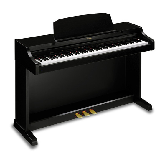
Digital Piano
SX-PX552 / SX-PX552M
Colours
(K) ...................Black (SX-PX552)
(M) ...................Walnut (SX-PX552M)
Areas
(P) U.S.A., Mexico
(PC) Canada
(EX) Norway, Sweden, Denmark, Finland, Switzerland, France,
Austria, Spain, Portugal, Holland, Belgium, Italy, Greece,
Poland,South Africa
(EZ) Germany
(EB) the United Kingdom
(XD) Hong Kong, Saudi Arabia, Kuwait
(XC) China
(XT) Taiwan
(XS) Malaysia, Singapore
(X) Thailand, Indnesia, Iran, U.A.E., Panama, Brasil, Philippines,
Venezuela, Ecuador, Colombia, Chile
(GN) Australia, New Zealand
1
Advertisement
Table of Contents

Related Manuals for Technics SX-PX552


Summary of Contents for Technics SX-PX552
- Page 1 ORDER NO. EMID0005008C0 Digital Piano SX-PX552 / SX-PX552M Colours (K) ....Black (SX-PX552) (M) ....Walnut (SX-PX552M) Areas (P) U.S.A., Mexico (PC) Canada (EX) Norway, Sweden, Denmark, Finland, Switzerland, France, Austria, Spain, Portugal, Holland, Belgium, Italy, Greece, Poland,South Africa (EZ) Germany (EB) the United Kingdom...
- Page 2 SPECIFICATIONS SPECIFICATIONS KEYBOARD 88 KEYS MAX. POLYPHONY 32 NOTES SOUND 8 SOUNDS : GRAND, UPRIGHT, E PIANO 1, E PIANO 2, HARPSI, VIBES, STRINGS, PIPE ORGAN PEDAL SOFT, SOSTENUTO, SUSTAIN DIGITAL EFFECT BRILLIANCE MELLOW, BRIGHT (5 STEPS) DIGITAL REVERB O (ROOM, STAGE, HALL, CONCERT) TOUCH SENSITIVITY LIGHT, NORMAL, HEAVY...
- Page 3 POWER REQUIREMENT 110W 100W (NORTH AMERICA AND MEXICO) AC120/ 220/ 230-240V 50/ 60Hz AC120V 60Hz (NORTH AMERICA AND MEXICO) AC230-240V 50/ 60Hz (EUROPE, AUSTRALIA, AND NEW ZEALAND) DIMENSIONES (W×H×D) 138.7cm×103.2cm×48.5cm (54-19/32”×40-5/8”×19-3/32”) NET WEIGHT 47kg (103.6lbs) ACCESSORIES AC CORD, MUSIC STAND 2000 Matsushita Electric Industrial Co., Ltd.
-
Page 4: Safety Precaution
the unfinished or rough edge of a part. 7. When replacing the power cord (except for the plug-in type), tug it from various directions to confirm that it does not slip out of place. 8. Spacing If soldering was done on the AC primary circuit, confirm that the interval between the soldered terminals or between the terminal and surrounding metallic parts is at least the minimum required (between the primary circuit and the chassis: at least 6.5 mm;... - Page 5 Measurements should range from 4 MOhm to infinity for all exposed parts. Figure-1 3. How to Assemble the Piano 4. Arrangement of Control Panel 5. Initial Setting The following procedure resets all programmable settings, functions and memories to their initialized (factory-preset) status. Use this procedure if the buttons, keys, etc.
- Page 6 7. Terminals 8. Parts Location 9. Disassembly Instructions 9.1. Removing the top cover and the keyboard cover [Fig. 1]...
-
Page 7: Removing The Control Panel
(Step2) Remove the top cover in the direction of arrows (refer to [Fig. 1]). (Step3) Remove the keyboard cover in the direction of arrow (refer to [Fig. 1]). 9.2. Removing the control panel - Follow the (Step1)-(Step3) of item 9.1. [Fig. - Page 8 9.4. Disassembly and assembly of key(s) - Follow the (Step1)-(Step3) of item 9.1. - Follow the (Step1)-(Step3) of item 9.2. - Follow the (Step1) of item 9.3. 9.4.1. Disassembly (Step1) Insert the thin solid board between white key and black key, push the claw (refer to [Fig.
-
Page 9: Disassembly Of The Pedal Assembly
9.4.2. Assembly (Step1) Insert the front part of the key into the chassis. (Step2) Insert the plate spring into the hammer notch (refer to [Fig. 5]). (Step3) While slowly lowering the key into the chassis, insert the plate spring into the notch at the rear of the key (refer to [Fig. -
Page 10: Removing The Printed Circuit Boards
9.6. Removing the speakers - Follow the (Step1)-(Step3) of item 9.1. 9.6.1. Removing the speaker box Remove 4 screws (refer to [Fig. 7]). 9.6.2. Removing the speakers Remove 4 screws (refer to [Fig. 7]). [Fig. 7] 9.7. Removing the printed circuit boards - Follow the (Step1)-(Step3) of item 9.1. - Page 11 - FJASP P.C.B. (Step1) Remove the 4 screws ×2 and ×2 (refer to [Fig. 8]). (Step2) Release the claws of the 3 P.C.B. holders. - COM P.C.B. (Step1) Remove the screw (refer to [Fig. 8]). (Step2) Release the claws of the 2 P.C.B. holders. - HP P.C.B.
-
Page 12: Symptoms Which Appear To Be Signs Of Trouble
Remove the CPR P.C.B. mounting screws ×1, ×1, ×3 and ×10 (refer to [Fig. 9]). [Fig. 9] 10. Symptoms Which Appear to be Signs of Trouble The following changes in performance may occur in the Technics Digital Ensemble but do not... - Page 13 indicate trouble. Phenomenon Remedy No sound is produced when the keyboard is No sound is produced if the MAIN VOLUME is set played. Use the sliding control to set the volume to an appropriate level. If the MIDI LOCAL CONTROL is set to off, set it to Nothing is shown on the display.
- Page 14 TEST MODE Procedure MAIN RAM (IC8, 9), ROM (IC6) 1. Connect the CHECKING DEVICE to CN9 on the MAIN P.C.B., check and turn on the CHECKING DEVICE switch. 2. Turn on the power switch. When the power switch is turned on, the LED of the CHECKING DEVICE flashes 8 times. first 4 flashes are for the RAM check , and the latter 4 flashes are for the ROM check.
-
Page 15: Test Mode
TEST MODE Procedure MAIN Wave ROM check 1. Press and hold the two E keys shown below, and then the power switch. MAIN: IC12 2. Select the POP GRAND sound. 3. Reduce the MAIN VOLUME level low enough. When set to the self-diagnostic mode, the Wave ROM outputs a sine wave. The Wave correspond to the keyboard keys as shown in the diagram to the right. -
Page 16: Midi Implementation Chart
TEST MODE Procedure Keyboard ROM (IC1) Press and hold the two A keys shown below, and then turn check power switch. If the keyboard ROM (IC1) is OK, the TOUCH SENSITIVITY LIGHT LED only flashes on control panel. If it is defective, the LEDs (LIGHT and NORMAL, or LIGHT, NORMAL and HEAVY) flash. Connection between serving CHECKING DEVICE and MAIN P.C.B. - Page 17 13.2. Important safety notice - Components identified by a mark have special characteristics impotant for safety. - When replacing any of these components, use only manufacture’s specified parts. 13.3. Symbolic Marks The symbolic marks for resistors and capacitors which used in this circuits are classified as following Table-1 and Table-2.
-
Page 18: Specification
SPECIFICATION TYPE SYMBOL Non-Polarized Electrolytic ECEA_KN_type Capacitors Non-Polarized Electrolytic ECEA_Y_type (for Network system) Tantalum Solid Electrolytic ECS_type Capacitors Metalized Plastic Film ECQV_type Capacitors (TF Series) Temperature Compensating ECC_type Ceramic Capacitors High-Dielecytric Constant ECK_type Ceramic Capacitors ECR_type Axial Lead Ceramic ECB_type Capacitors Metalized Polyester Film ECQ_EW_type... - Page 20 14.2. Measuring Condition of FJASP P.C.B.
- Page 21 15. Schematic Diagram 16. Printed Circuit Board Diagram 17. Block Diagram 18. Wiring Connection Diagram 19. Replacement Parts List Notes: *Important safety notice: / Components identified by mark have special characteristics important for safety. / Funrthermore, special parts which have purposes of fire-retardant (resistors), high-quality sound (capacitors), low-noise (resistors), etc.
- Page 22 13-1 SBLG230A STAY QKQGA136AAZ TOP COVER ASS'Y QKQGA136ABZ TOP COVER ASS'Y 14-2 QMFG1274AA FELT 14-3 QMFG1057AA FELT 14-4 SGBG160B TECHNICS BADGE QKQGF036AAZ KEYBOARD COVER ASS'Y QKQGF036ABZ KEYBOARD COVER ASS'Y 15-1 QMRG7056AA HOLDER 15-2 QWBG002AA HOLDER 15-3 QXQG007AA AXLETREE 15-4 QGKG0140AA...
- Page 23 Ref. No. Part No. Part Name & Description Remarks QKQGN989AAZK LEFT PLANK QKQGN989ABZK LEFT PLANK QKQGN990AAZK RIGHT PLANK QKQGN990ABZK RIGHT PLANK QKQGM105AAZ PEDAL BOX ASS'Y QKQGM105ABZ PEDAL BOX ASS'Y 27-1 QGKG0113AA ORNAMENT QMBG009AA SPRING QMFG1133AA FELT QMFG1134AA FELT QMWG4002AA PEDAL ARM QMFG1135AA FELT QKAG0011AA...
- Page 24 Ref. No. Part No. Part Name & Description Remarks XTB35+14A SCREW XTN4+16F SCREW XYA35+JA12 SCREW XTW3+10Q SCREW XTW3+20TFZ SCREW XTT4+12AFZ SCREW XYA35+JA12 SCREW XYN3+C8FZ SCREW XTV3+10JFZ SCREW XYN4+F16 SCREW XTT4+20A SCREW QHDG021AA SCREW QHWG007AA QHDG055AA SCREW XTT4+25A SCREW GTT4+25AFZ SCREW QHDG016AB SCREW WITH WASHER XTB35+16A...
- Page 25 QCBG1H104ZFA 50V 0.1U...
- Page 26 Ref. No. Part No. Part Name & Description Remarks ECBT1E223ZF5 25V 0.022U ECRF1H104ZF 50V 0.1U ECRR1H104ZF1 50V 0.1U MAIN ECA1VM472 35V 4700 FJASP ECEA0JKA470 6.3V 47U MKB1 ECEA0JKS101 6.3V 100U ECEA1HKA010 50V 1U MAIN ECRF1H104ZF 50V 0.1U MKB2 ECA1VM472 35V 4700 FJASP ECRF1H104ZF 50V 0.1U...
- Page 27 Ref. No. Part No. Part Name & Description Remarks EECS5R5V105 5.5V 1 MAIN ECEA1HKN010 50V 1U FJASP ECUV1H104ZFX 50V 0.1U MAIN ECQB1H473JF 50V 0.047U FJASP ECQB1H333JF 50V 0.0033U FJASP ECQG1H682KZ 50V 0.0068U FJASP ECQV1H224JM 50V 0.22U FJASP ECQG1H472KZ 50V 0.0047U FJASP ECQB1H473JF 50V 0.047U...
- Page 28 Ref. No. Part No. Part Name & Description Remarks C85,86 ECUV1H101JG 50V 100P MAIN ECRR1H104ZF1 50V 0.1U MAIN ECA1VM470 35V 47 MAIN ECRR1H104ZF1 50V 0.1U MAIN ECUV1H101JG 50V 100P MAIN ECA0JM102 6.3V 1000U MAIN ECUV1H102JX 50V 0.01U MAIN ECUV1H102JX 50V 0.01U MAIN C107 ECUV1H101JG...
- Page 29 D3,D4 MA165 DIODE MKB1...
- Page 30 Ref. No. Part No. Part Name & Description Remarks SVDGS3V20-15 DIODE FJASP D5,D6 MA165 DIODE MKB1 SVDGS3V20-15 DIODE FJASP MA165 DIODE MKB1 SVDGS3V20-15 DIODE FJASP MA111 DIODE MAIN MA165 DIODE MKB1 MA111 DIODE MAIN MA165 DIODE MKB1 MA165TA5 DIODE SVDGS3V20-15 DIODE FJASP MA111...
- Page 31 Ref. No. Part No. Part Name & Description Remarks MA165TA5 DIODE MA111 DIODE MAIN MA165 DIODE MKB1 MA165TA5 DIODE MA111 DIODE MAIN MA165 DIODE MKB1 MA111 DIODE MAIN MA165 DIODE MKB1 MA111 DIODE MAIN D29,30 MA165 DIODE MKB1 MA165TA5 DIODE FJASP MA111 DIODE...
- Page 32 Ref. No. Part No. Part Name & Description Remarks D232-42 LN282RPXVTX2 D244-46 LN282RPXVTX2 D256-59 LN282RPXVTX2 D265-67 LN282RPXVTX2 D280-83 LN282RPXVTX2 D288 LN282RPXVTX2 D291 LN282RPXVTX2 XBA1C40NU100 FUSE,4A FJASP(P,PC,PY) XBA2C16TB0 FUSE,T1.6A FJASP(X,XS,XD,XT,XA) XBA2C10TB0 FUSE,T1.0A FJASP(X,XS,XT,XD,XA) XBA2C10TB0 FUSE,T1.0A FJASP(EX,EZ,EG,EB,GN) XBA2C10TB0 FUSE,T1.0A FJASP(X,XS,XD,XT,XA) XBA2C16TB0 FUSE,T1.6A FJASP(EX,EZ,EG,EB,GN) XBA2C16TB0 FUSE,T1.6A...
- Page 33 Ref. No. Part No. Part Name & Description Remarks IC26 M5218AFPE3 MAIN QJJG010AA JACK,HEADPHONE QJSG007AA JACK,PEDAL IN FJASP QJSG017AA JACK,COMPUTER QJJG010AA JACK,HEADPHONE QJSG016AA JACK,MIDI IN FJASP QJSG016AA JACK,MIDI OUT FJASP QJJG003AA JACK,AUX L FJASP QJJG003AA JACK,AUX R/R+L FJASP QJJG003AA JACK,LINE OUT L FJASP QJJG003AA JACK,LINE OUT R/R+L...
- Page 34 Ref. No. Part No. Part Name & Description Remarks 2SC1815TPE2 TRANSISTOR FJASP 2SA1015TPE2 TRANSISTOR FJASP 2SA830STPB TRANSISTOR 2SD601AQ TRANSISTOR MAIN 2SA830STPB TRANSISTOR 2SC1815TPE2 TRANSISTOR FJASP 2SA1015TPE2 TRANSISTOR FJASP 2SA830STPB TRANSISTOR 2SD601AQ TRANSISTOR MAIN 2SA1015TPE2 TRANSISTOR FJASP 2SA830STPB TRANSISTOR 2SD601AQ TRANSISTOR MAIN 2SB621ARS TRANSISTOR...
- Page 35 Ref. No. Part No. Part Name & Description Remarks ERDS2TJ471 1/4W 470 ERDS2TJ472 1/4W 4.7K ERDS2TJ473 1/4W 47K FJASP ERJ6GEYJ104V 1/10W 100K MAIN ERDS2TJ103 1/4W 10K FJASP ERDS2TJ472 1/4W 4.7K ERJ6GEYJ101V 1/10W 100 MAIN ERDS2TJ103 1/4W 10K ERDS2TJ332 1/4W 3.3K FJASP ERDS2TJ472 1/4W 4.7K...
- Page 36 Ref. No. Part No. Part Name & Description Remarks ERDS2TJ222 1/4W 2.2K FJASP ERJ6GEYJ471V 1/10W 470 MAIN ERDS2TJ101 1/4W 100 ERDS2TJ220 1/4W 220 FJASP ERJ6GEYJ471V 1/10W 470 MAIN ERD25FVJ4R7 FJASP ERDS2TJ101 1/4W 100 ERJ6GEYJ471V 1/10W 470 MAIN ERD2FCVG220 FJASP ERDS2TJ101 1/4W 100 ERJ6GEYJ471V 1/10W 470...
- Page 37 ERDS2TJ394 1/4W 390K FJASP Ref. No. Part No. Part Name & Description Remarks ERJ6GEYJ221V 1/10W 220 MAIN ERDS2TJ332 1/4W 3.3K FJASP ERJ6GEYJ221V 1/10W 220 MAIN ERDS2TJ224 1/4W 220K FJASP ERJ6GEYJ221V 1/10W 220 MAIN ERDS2TJ103 1/4W 10K FJASP ERJ6GEYJ221V 1/10W 220 MAIN ERDS2TJ182 1/4W 1.8K...
- Page 38 Ref. No. Part No. Part Name & Description Remarks ERDS2TJ331 1/4W 330 FJASP ERJ6GEYJ101V 1/10W 100 MAIN ERD2FCVG101 FJASP ERJ6GEY0R00V 1/10W 0 MAIN ERD2FCVJ4R7 FJASP ERJ6GEYJ471V 1/10W 470 MAIN R96,97 ERJ6GEYJ331V 1/10W 330 MAIN ERJ6GEYJ473V 1/10W 47K MAIN R99,00 ERDS2TJ681 1/4W 680 FJASP R102...
-
Page 39: Cabinet Parts Location
Ref. No. Part No. Part Name & Description Remarks QTPG1M025A POWER TRANSFORMER EX,EB,EZ,EG,X,GN,XS,XT QTPG1M025A POWER TRANSFORMER XD,XA QRVG25P01B53 V.R.,VOLUME QJLG013AA PEDAL CORD QEXGST16060B WIRE WITH CONNECTOR QEXGVH03105B WIRE WITH CONNECTOR QEXGSS16022C WIRE WITH CONNECTOR QEXGSS05028A WIRE WITH CONNECTOR QEXGSS06030B WIRE WITH CONNECTOR QEXGSS07010A WIRE WITH CONNECTOR QEXGSS12010A... - Page 41 21. Manual Keyboard Parts Location...
- Page 42 22. Packaging...
- Page 43 Printed in Japan / H000505300 KA/HH...
-
Page 45: Headphones (Phones)
(On the back of piano) LINE OUT AUX IN MIDI COMPUTER PEDAL IN R + L R + L MIDI PEDAL IN COMPUTER Connect the cord from the included stand to this By connecting this terminal to the serial port of terminal. - Page 47 MAIN CIRCUIT +5D 2 1.5K SOFT 3 1.5K FJASP SOSU 4 1.5K SUST 5 MRXD 6 MTXD 7 2SB709ARTX 2.2K MA8030HTX 0.22 2SD601AQTX 0.22 100K 100K SW 2 CHECK TERMINAL LED 3 +5D 4 MAC 1 PC1 2 M5M34051FPE2 PC2 3 (BUS TRANSCEIVER) MIDI 4 MSEL 5...
- Page 48 2SD601AQTX +15V R113 2SB709ARTX R114 4.7K MA8056MTX A B C A B C D E F G H I J K L 100x4 P70/PG00 P71/PG01 P72/PG02 P61/CS1 P73/PG03 P62/CS2 P20/A16 P74/PG10 P63/CAS P21/A17 P75/PG11 P64/RAS P22/A18 P76/PG12 P65/REFOUT P23/A19 P77/PG13 P24/A20 P25/A21 P80/TXD0...
- Page 49 C27 0.1 2SB621ARSTA QLQGT1B101KA 100x4 100P EK04W 2SC1815TPE2 100x4 D74HC139GSE2 100x4 (DECORDER) 100x4 A B C 2SD601AQTX 3.3K D6 13 D5 14 D4 15 D3 16 D2 17 D1 18 D0 19 QSIGX3C04005 M5256DFP70LL M5256DFP70LL /SQTG9011A (256KBIT STATIC RAM) (256KBIT STATIC RAM) /X27C4096DC10 (4MBIT MASK ROM)
- Page 50 A B C N H I G J F D K C B A H A G B F +3.3 TG CLOCK NRSTSG RAMDT2 NRSTCPU RAMDT4 RAMDT3 SDIREV SDOREV SDICH0 SDOCH0 SDIDRY SDODRY TEMODE3 TEMODE2 2.2K DIVOUT SDOMIX LRCK IC10 ROMDT11 D97315GD201 ROMDT4...
- Page 51 IC14 TC7W08FTE12L (DUAL 2-INPUT AND GATE) VCC BYTE R201 1 2 3 4 5 6 7 8 AD21 10uH QLBG002A IC15 TC7W04FTE12L (TRIPLE INVERTER) 2SC1815TPE2 +3.3 +VCC R202 1 2 3 4 5 6 7 8 VSS VSS R65 1M MA1039HTR IC12 IC11...
- Page 52 C107 100P C116 6.3V47 IC21 R106 100K PCM1734EA-E2 (D/A CONVERTER) IC26 M5218AFPE3 C60 0.1 (OP.AMP) 330x4 +15V LRCK ML/IIS PMUT DATA MC/DW1 C108 FJASP +VCC BCK MD/DW0 CLKO MUTE -VCC -15V MODE +15V CS/IW0 R102 SUMR DGND SUML ZERO R107 VCC2R VCC2L 100K AG2R...
- Page 53 FJASP CIRCUIT PRODUCTS FOR X XS XT XD XA POWER TRANSFORMER QSRGT006AA BLUE 4700P BLACK JK9 L1 POWER QLQGT2T100LA CORD BLUE ERA1502V5 ERA1502V5 PRODUCTS FOR P PC 4700P JK9 L1 QLQGT2T100LA LINE OUT L 0.0022 LINE OUT R /R+L 0.0022 PRODUCTS FOR OTHERS 4700P AUX L...
- Page 54 KIA7815PI +15M +VCC (+15 VOLTAGE REGULATOR) 2SA1015TPE2 4.7K MA4180TA SVDGS3V20-15 SVDGS3V20-15 35V4700 16V10 2SA1015TPE2 2SA1015TPE2 35V4700 16V330 SVDGS3V20-15 +15HM 4.7K EK04W MA4180TA SVDGS3V20-15 2SC1815TPE2 3.3K -VCC -15M KIA7915PI (-15 VOLTAGE REGULATOR) 2SC1815TPE2 130uHx3 PMUT 2SC1815TPE2 R100 100K MA165TA5 PMUT 130uHx3 R40 10K 0.015 0.033...
- Page 55 PINL R67 560K +VCC 0.033 0.0022 +15M W6E05 390K 2SA1725PY 2.7K 2SC1815TPE2 +VCC MA165TA5 0.022 M5218AL (EQUALIZING) MA165TA5 -VCC +15M 2.7K 2SA1015TPE2 W6E05 0.033 0.0022 -15M 2SC4511PY EK04W +VCC 390K IC11 M5218AL -VCC (POWER AMPLIFIER) +VCC -VCC +15M 0.0068 0.001 W6E05 2SA1725PY 3.3K...
- Page 56 R102 PEDAL IN R104 +5DM R106 +5DM R110 MIDI OUT R111 MA165TA5 2SA933STRS 220P MA165TA5 IC12 QCPL-260L (PHOTO COUPLER) R113 MIDI IN +5DM R114 MA165TA5 VOUT 0.047 50V1 EOINL 330K C43 10P 2SB621ARSTA R25 270K 2.2K 2SD592ARSTA +VCC M5218AL (HEADPHONE AMPLIFIER) -VCC 2SB621ARSTA 2.2K...
- Page 57 CPL CIRCUIT +5IP M37471M2196S (8BIT MICROCOMPUTER) +5IP EF0MC4004T5 4.7K XOUT R2 0 R3 0 +5IP 0.022 6.3V100 R4 100 +5IP VREF DATA 2SA830STPB 6.3V100 MAIN 2SA830STPB R5 470 R6 220 SOUT 2SA830STPB R7 220 R8 470 CNTR1 2SA830STPB +5IP 100K 2SA830STPB SUMR SUML...
- Page 58 SW81 SW89 SW73 PIPE DIGITAL E.PIANO2 ORGAN REVERB SW66 SW74 GRAND HARPSI SW59 SW67 SW75 DEMO UPRIGHT VIBES SW60 SW84 SW68 SW76 MODE DIGITAL E.PIANO1 STRINGS EFFECT D256 D257 D258 D259 LN282RPXVTX2 LN282RPXVTX2 LN282RPXVTX2 LN282RPXVTX2 E.PIANO2 HARPSI VIBES STRINGS D265 D266 D267 LN282RPXVTX2...
- Page 59 CPR CIRCUIT TEMP MELLOW DOWN SW10 TEMP BRIGHT D232 D233 LN282RPXVTX2 LN282RPXVTX2 MELLOW BRIGHT D240 D241 LN282RPXVTX2 LN282RPXVTX2 METRONOME VOLUME...
- Page 60 SW17 SW33 SW25 SW41 SW49 START TRANSPOSE TRACK1 METRONOME TOUCH /STOP DOWN SW34 SW18 SW26 SW42 TRANSPOSE RECORD TRACK2 VOLUME D234 D235 D236 D237 D238 LN282RPXVTX2 LN282RPXVTX2 LN282RPXVTX2 LN282RPXVTX2 LN282RPXVTX2 START/STOP RECORD TRACK1 TRACK2 TRANSPOSE DOWN D242 D244 D245 D246 LN282RPXVTX2 LN282RPXVTX2 LN282RPXVTX2...
- Page 61 10 27 23 17 28 22 12 14 19 18 D239 LN282RPXVTX2 TRANSPOSE UP 21 16 24 20 15 LED1 T512SRDBS119...
- Page 62 MKB1 CIRCUIT HD74LS138P +VCC (3 TO 8 DECODER) 6.3V47 MAIN UNLESS OTHERWISE SPECIFIED: DIODES ARE MA165.
- Page 64 MKB2 CIRCUIT UNLESS OTHERWISE SPECIFIED: DIODES ARE MA165.
- Page 65 HD74LS138P (3 TO 8 DECODER) +VCC...
- Page 66 HD74LS138P (3 TO 8 DECODER) +VCC...
- Page 68 PKB CIRCUIT PEDAL CORD CN1 +5 PEDAL QSTGT001AA QSTGT001AA QSTGT001AA 4.7K 4.7K 4.7K COM CIRCUIT COMPUTER MIDI MSEL MAIN WGE05 TXD- MIDI TXD+ 1,7,8 COMPUTER RXD+ WGE05 RXD- WGE05 WGE05 WGE05 WGE05...
- Page 69 MAIN P.C.B. (COMPONENT SIDE) Z32 Z21 Z20 Z19 Z18 Z17 TG CLOCK R204 C108 IC12 C121 IC10 R102 IC11 IC21 C107 R106 R201 IC26 C120 R107 C109 C110 R202 R27 R28 Z1 Z2 Z3 R116 RESET R111 R112...
- Page 70 ELECTRICAL PARTS LOCATION Ref.No. Lo.No. Ref.No. Lo.No. Ref.No. Lo.No. Ref.No. Lo.No. Ref.No. Lo.No. MAIN P.C.B. (COMPONENT SIDE) R102 IC10 R106 IC11 R107 IC12 R111 IC21 R112 IC26 R116 R201 R202 R204 C107 C108 C109 C110 C120 C121...
- Page 71 MAIN P.C.B. (FOIL SIDE) L30 L29 L16L17L18 L19L20L21L22 D25D26 C111 R113 IC14 R114 R200 R104 IC15 R117 R118...
- Page 72 ELECTRICAL PARTS LOCATION Ref.No. Lo.No. Ref.No. Lo.No. Ref.No. Lo.No. Ref.No. Lo.No. Ref.No. Lo.No. MAIN P.C.B. (FOIL SIDE) IC14 IC15 R104 R113 R114 R117 R118 R200 C111...
- Page 73 FJASP P.C.B. PMUT J11 R16 R102 R116 R104 J15 J14 R106 R115 R113 R56 C32 R60 C36 IC10 IC12 J30 J29 R114 D12 C10 R24 J66 R18 R20 R110 R45 C21 R41 C17 R31 R34 J105 R111 J104 SUMR J106 J100 SUML P PC...
- Page 74 ELECTRICAL PARTS LOCATION Ref.No. Lo.No. Ref.No. Lo.No. Ref.No. Lo.No. Ref.No. Lo.No. Ref.No. Lo.No. FJASP P.C.B. IC10 R100 IC11 R102 IC12 R104 R106 R110 R111 R113 R114 R115 R116...
- Page 75 CPL P.C.B. JP10 J1 J2 GRAND D265 MODE SW59 SW66 SW60 DEMO JP17 JP12 JP11 PIPE UPRIGHT E.PIANO1 E.PIANO2 VIBES STRINGS ORGAN R34 R35 DIGITAL D266 D267 D256 D257 D258 D259 D291 D288 J36 J37 REVERB D280 D281 DIGITAL SW74 D282 EFFECT SW67...
- Page 76 CPR P.C.B. J5 J6 MELLOW BRIGHT METRONOME D233 D232 D240 VOLUME /BEAT LED1 D241 TEMPO TEMPO DOWN D242 SW10 SW41 SW42 START TRANSPOSE TRANSPOSE /STOP RECORD TRACK1 TRACK2 DOWN D237 D238 D239 D236 D235 D234 TOUCH D244 D245 D246 SW18 SW25 SW33 SW17...
- Page 77 MKB1 P.C.B. D72 D70 SW40 SW38 SW37 SW35 SW32 SW31 SW30 SW29 SW28 SW27 SW26 SW25 SW24 SW23 SW43 SW42 SW41 SW39 SW36 SW34 SW33 SW44 D25 J6 SW22 SW21 SW20 SW19 SW18 SW16 SW15 SW14 SW13 SW12 SW11 SW10 SW17 ELECTRICAL PARTS LOCATION Ref.No.
- Page 78 MKB2 P.C.B. D142 D138 D134 D176 D174 D172 D170 D168 D166 D164 D162 J17 D160 D158 D156 D154 D152 D150 D148 D146 D144 D140 D136 D167 D165 D163 D159 D157 D155 D151 D149 D147 D145 D137 D135 D133 D175 D173 D171 D169 D161...
- Page 79 PKB P.C.B. JR1 JR3 SUSTAIN SOSUTENUTO SOFT ELECTRICAL PARTS LOCATION Ref.No. Lo.No. Ref.No. Lo.No. Ref.No. Lo.No. Ref.No. Lo.No. PKB P.C.B.
- Page 80 COM P.C.B. ELECTRICAL PARTS LOCATION Ref.No. Lo.No. Ref.No. Lo.No. Ref.No. Lo.No. COM P.C.B. HP P.C.B. HEADPHONE1 HEADPHONE2 POWER INDICATOR ELECTRICAL PARTS LOCATION Ref.No. Lo.No. Ref.No. Lo.No. Ref.No. Lo.No. Ref.No. Lo.No. Ref.No. Lo.No. HP P.C.B.
- Page 81 MKB1 MKB2 DECODER COMPUTER SWITCHES MIDI & DECODER DECODER DIODES SWITCHES & DIODES IC10 SDOMIX RXD,TXD,SCKIN,SCKOUT CRXD CTXD MAC,PC1, KDB0 KDB4 KDB0 KDB4 PC2,MIDI KF3, KS0 KF3, KS0 16BIT TONE MICROCOMPUTER GENERATOR SOFT, SODU, MRXD MTXD SUST DATA BUS D0 D19 D8 D15 D0 D7 4M BIT...
- Page 82 MAIN SWITCHES & LEDS SWITCHES & LEDS +15V +5A REGULATOR IC2,3 Q2 6 BUFFER LED DRIVE MAIN -15V VOLUME SEG0 SEG11 CM0 CM5 SW0 SW7 LED1 8BIT MICROCOMPUTER +VCC DATA,SCK LED DISPLAY Q7,8 +5D REGULATOR +3.3V +3.3V REGULATOR IC21 IC26A CONVERTER IC26B WD0A...
- Page 83 FJASP +15V +VCC D7,8 +15V POWER REGULATOR POWER TRANSFORMER SWITCH -15V -VCC D5,6 -15V REGULATOR AC CORD +VCC IC11B IC3B IC5,6,9,10A Q11,12,15,16 SP1 (Lch) 14cm; 4 IC11A IC3A IC7,8,9,10B Q13,14,17,18 SP2 (Rch) 14cm; 4 MIXING EQUALIZING POWER AMPLIFIER POWER INDICATOR +15V IC4A Q7,8...
- Page 84 COM P.C.B. MAIN P.C.B. QEXGSS07010A QEXGSS12010A QEXGST160608 QEXGHVH02055C CORE CORE QEXGSS16022C CPL P.C.B. 14cm,6 CORE MKB1 P.C.B. QEXGSS16022C QEXGSS16022C HP P.C.B.
- Page 85 AC CORD FJASP P.C.B. AC IN POWER TRANSFORMER POWER SWITCH QEXGVH03105B QEXGVH02040B CPR P.C.B. 14cm,6 MKB2 P.C.B. PKB P.C.B.
Need help?
Do you have a question about the SX-PX552 and is the answer not in the manual?
Questions and answers
The keyboard turns on but I get no sound. The volume is up?Sx-PX552
There may be no sound from the Technics SX-PX552 keyboard due to the following reasons:
1. Main Volume Set to Minimum – If the MAIN VOLUME is set to MIN, no sound will be produced. Adjust the sliding control to an appropriate level.
2. MIDI LOCAL CONTROL Set to Off – If MIDI LOCAL CONTROL is off, turn it on.
3. Incorrect COMPUTER Terminal Switch Setting – If the COMPUTER terminal switch is not set to MIDI, turn off the keyboard and set the switch to MIDI.
4. Mismatched MIDI Channels – Ensure that the transmitting and receiving MIDI channels match.
Check these settings to restore sound output.
This answer is automatically generated