
Related Manuals for Kenmore PG-40409S0LB-COSG


Summary of Contents for Kenmore PG-40409S0LB-COSG
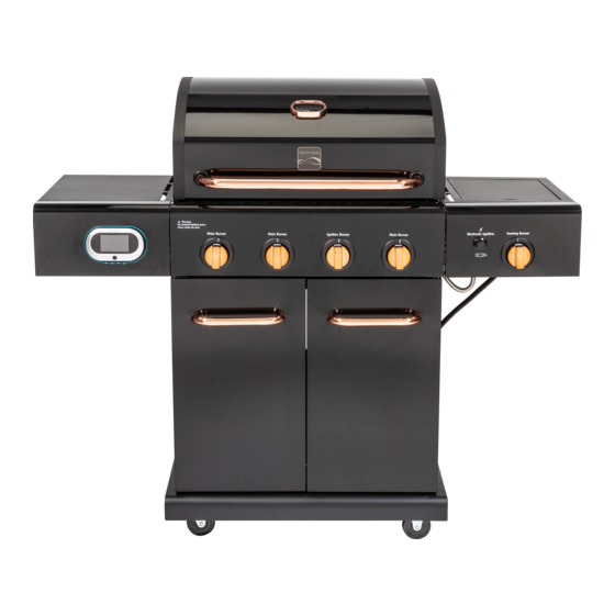
- Page 1 User & Care Guide Manual de Uso y Cuidado English / Español Liquid Propane Gas Grill Parrilla a gas de propano líquido Model/Modelo : PG-40409S0LB-COSG PG-40409S0LB-BKSG...
-
Page 2: Table Of Contents
Kenmore Warranty ........ -
Page 3: For Your Safety
Installation Safety Precautions • Please read this User’s Manual in its entirety before using the CARBON MONOXIDE HAZARD grill. • Failure to follow the provided instruction can result in seriously If you smell gas: bodily injury and / or property damage. •... -
Page 4: Kenmore Warranty
WARRANTY KENMORE LIMITED WARRANTY WITH PROOF OF SALE: the following warranty coverage applies when this appliance is correctly installed, operated and maintained according to all supplied instructions. Note: Consumer is responsible for Shipping &handling of all warranty replacement parts. FOR ONE YEAR: from the date of sale this grill is warranted against defects in material or workmanship, consumer will receive free replacement parts with proof of purchase, consumer is responsible for Shipping &... -
Page 5: Use And Care
LP Cylinder USE AND CARE • The LP cylinder used with your grill must meet the following requirements: • Use LP cylinders only with these required measurements: 12" CARBON MONOXIDE HAZARD (30.5cm) (diameter) x 18" (45.7 cm) (tall) with 20 lb. (9 kg.) Capacity maximum. - Page 6 Connecting Regulator to the LP Tank LP Tank Exchange • Many retailers that sell grills offer you the option of LP tank must be properly secured onto grill. (Refer to replacing your empty LP tank through an exchange service. assembly section.) Use only those reputable exchange companies that 2.
- Page 7 Leak Testing Valves, Hose and Regulator Turn all grill control knobs to OFF. 2. Be sure regulator is tightly connected to LP tank. 3. Completely open LP tank valve by turning OPD hand wheel counterclockwise. If you hear a rushing sound, turn gas off immediately.
- Page 8 Safety Tips WARNING ▲ Before opening LP cylinder valve, check the coupling nut for tightness. ▲ When grill is not in use, turn off all control knobs and LP cylinder valve. For Safe Use of Your Grill and to Avoid Serious ▲...
- Page 9 Burner Flame Check • Remove cooking grates and heat diffusers. Light burners, turn WARNING knobs from HI to LO. You should see a smaller flame in LO position than seen on HI. Perform burner flame check on searing burner, also. Always check flame prior to each use. If only low Turn controls and gas source or tank OFF when flame is seen refer to "Sudden flame drop or low flame"...
- Page 10 • Painted surfaces: Wash with mild detergent or nonabrasive Safety Tips cleaner and warm soapy water. Wipe dry with a soft • Clean cooking grates. nonabrasive cloth. • Store in dry location. • Stainless steel surfaces: To maintain your grill’s high quality •...
- Page 11 Food Safety Food safety is a very important part of enjoying the outdoor cooking experience. To keep food safe from harmful bacteria, follow these four basic steps: Clean: Wash hands, utensils, and surfaces with hot soapy water before and after handling raw meat and poultry. Separate: Separate raw meats and poultry from ready-to-eat foods to avoid cross contamination.
-
Page 12: Parts List
PARTS LIST (1/2) Description Part Number Description Part Number Control Knob Bezel Side Burner Lid 40200500 19-A 40920036 (Matte Black) Control Knob Bezel Rotate Rod, Side Burner Lid 40900221 19-B 40900502 (Black Chrome) Control Knob, Main Burner Side Burner Grid 40900222 20-A 40920206... - Page 13 PARTS LIST (2/2) Description Part Number Description Part Number Door Handle 35-A 40920076 Silicone Rubber Bumper 50300205 (Copper Chrome) Door Handle Temperature Gauge 35-B 40900503 55-A 40920218 (Black Chrome) (Copper Chrome) Temperature Gauge Left Door (Black) 40920127 55-B 40900201 (Black Chrome) Cotter Pin 10050 Logo (Black Chrome)
-
Page 14: Parts Diagram
PARTS DIAGRAM... -
Page 15: Before Assembly
BEFORE ASSEMBLY NOTICE: Once you have unpacked the grill according to the STOP SHEET instructions, check all grill parts against the pictures on this and the following two pages. If your parts are missing or damaged, call 1-888- 287-0735. M-F 8:00 – 5:00 PST. - Page 16 BEFORE ASSEMBLY...
- Page 17 BEFORE ASSEMBLY...
-
Page 18: Assembly
ASSEMBLY CAREFULLY READ AND PERFORM ALL ASSEMBLY INSTUCTIONS ON THE FOLLOWING PAGES. Tools Required: • Adjustable wrench (not provided) • Screwdriver (not provided) • 7/16” Combination wrench (not provided) • The following hardware is provided in blister pack for convenient use. M4 x 10 Screw AA Battery Qty: 36 pcs... - Page 19 Bottom Shelf Turn bottom shelf upside down. Attach the casters to bottom shelf with (16) M6x13 screws. Note: Install each caster into the correct position as shown in the figure below. The standard caster (non-swiveling) will only install in one direction. ...
- Page 20 Cart To attach side panels, align side panel holes with screw insert holes on each side of bottom shelf. Note: Left side panel has match holder attachment. Attach left and right side panels to sides of bottom shelf with (4) M6x13 screws. (A) ...
- Page 21 Front Door Remove the (4) M5x15 screws pre-assembled to the door handle ends, and use them to attach handles to doors. See A Insert the pin at the bottom of each door into the hole on the bottom panel. Insert the pin at the top of each door through the hole in the door bracket hinge.
- Page 22 Grill Head to Cart This step requires two people to lift and position grill head onto cart. If not already done, remove the tie wrap and packing material from regulator hose, side burner valve and igniter wires. Pull hose and igniter wire out to side of grill head. ...
- Page 23 Left Side Shelf Attach fascia to left side shelf with (2) M5x10 screws and (2)M5 flat washers. Attach Shelf Support Angle Bar to side shelf and fascia with (4) M4x10 screws. Hang left side shelf onto the brackets on left side of firebox. ...
- Page 24 Right Side Shelf Attach fascia to right side shelf with (2) M5x10 screws and (2)M5 flat washers. Attach Shelf Support Angle Bar to side shelf and fascia with (4) M4x10 screws. Hang right side shelf onto the brackets on left side of firebox. ...
- Page 25 Searing Burner Remove plastic packaging from searing burner valve. Remove searing burner grate from searing burner shelf. Remove the 2 pre-installed screws from the valve control stem and set them aside. (A & B) Loosen the searing burner to insert gas valve. First loosen and remove the screw attaching the electrode etc. (C) to the shelf and set it aside.
- Page 27 Heat Diffuser, Cooking Grates and Warming Rack Place heat diffusers over burners. Diffusers will fit in firebox in either direction. Fit tabs in firebox front through slots in diffuser tips. Fit diffuser tips over tabs in firebox rear. Place cooking grates onto grate rests at front and rear of firebox. ...
- Page 28 Drip Tray, Drip Cup and LP Tank Slide drip tray into bottom of firebox from back. Hang drip cup clip from bottom of drip tray. Make sure the drip drainage hole is on the right side, as seen from the back of the grill. Place drip cup into drip cup clip. ...
-
Page 29: Troubleshooting
EMERGENCIES: If a gas leak cannot be stopped, or a fire occurs due to gas leakage, call the fire department. Problem Possible Cause Prevention/Solution • Damaged hose. • Turn off gas at LP cylinder or at source on natural gas systems. If Gas leaking from cracked/cut/burned hose. - Page 30 Troubleshooting (continued) Problem Possible Cause Prevention/Solution • See Section I of Electronic Ignition System. Burner(s) will not light using ELECTRONIC IGNITION: • No spark, no ignition noise. igniter. • No spark, some ignition noise. • See Section II of Electronic Ignition System. (See Electronic Ignition •...
- Page 31 Troubleshooting – Electronic Ignition Problem Possible Cause Check Item Prevention/Solution • Battery not installed • Check battery orientation. • Install battery (make sure that “+” and “-” SECTION I No sparks appear properly. connectors are oriented correctly, with “+” end •...
- Page 32 Garantía para la parrilla Kenmore........
-
Page 33: Por Su Propia Seguridad
Precauciones de instalación PELIGRO • Por favor lea este Manual del usuario en su totalidad antes de usar la parrilla. • El incumplimiento de la instrucción proporcionada puede Si siente olor a gas : resultar en lesiones graves o daños a la propiedad. •... -
Page 34: Garantía Para La Parrilla Kenmore
WARRANTY GARANTÍA LIMITADA DE KENMORE CON LA PRUEBA DE VENTA: se aplica la siguiente cobertura de garantía cuando este dispositivo se instala, opera y mantiene correctamente de acuerdo con todas las instrucciones suministradas. Nota: El consumidor es responsable del envío y manejo de todas las piezas de repuesto bajo garantía. -
Page 35: Uso Y Mantenimiento
Tanque de gas propano UOS Y MANTENIMIENTO • El cilindro de gas LP con la parrilla debe cumplir los siguientes requisitos: • Utilice cilindros de propano licuado solo con estas medidas PELIGRO requiere: 12"(30,5 cm) (diámetro) x 18" (45.7 cm) (alto) con 20 libras (9 kg.) Capacidad máxima. - Page 36 Como conectar el regulador al tanque de gas propano Cambio del tanque de gas • Muchos comerciantes minoristas que venden parrillas, le El tanque del LP se debe asegurar correctamente sobre ofrecen la opción de cambiar su tanque de gas vacío parrilla.
- Page 37 Prueba para detectar fugas de las válvulas, las mangueras y el regulador Gire todas las perillas de control de la parrilla a la posición deAPAGADO. 2. Cerciórese de que el regulador esté bien conectado al tanque de gas. 3. Abra por completo la válvula del tanque, girando la manilla Sostenga la tuerca de unión en sentido contrario a las agujas del reloj.
- Page 38 Consejos de seguridad ADVERTENCIA ▲ Antes de abrir la válvula del cilindro LP, verifique que la tuerca de acoplamiento esté apretada. ▲ Cuando la parrilla no esté en uso, apague todas las perillas de Para usar su parrilla en forma segura y para control y la válvula del cilindro LP.
- Page 39 Comprobación de llama del quemador • Retire las parrillas de cocción y los difusores de calor. Encienda los ADVERTENCIA quemadores, gire las perillas de HI a LO. Debería ver una llama más pequeña en la posición LO que se ve en HI. Realice la verificación de la llama del quemador en el quemador abrasador, también.
- Page 40 • Superficies pintadas: Lave con un detergente suave o un Cómo guardar su parrilla limpiador no abrasivo y agua jabonosa tibia. Secar con un • Limpie las parrillas de cocción. paño suave no abrasive. • Guárdela en un lugar seco. •...
- Page 41 Seguridad alimentaria La seguridad alimentaria es una parte muy importante del disfrute de su parrillada al aire libre. Para mantener los alimentos a salvo de las bacterias dañinas, siga estos cuatro pasos básicos: Limpiar: Lávese las manos, los utensilios y las superficies con agua caliente y jabón antes y después de manipular carnes y aves crudas.
-
Page 42: Lista De Piezas
LISTAR DE PIEZASTES (1/2) Llave Descripción Cant. Numero de Llave Descripción Cant. Numero de Bisel de la perilla de control Tapa del quemador lateral 40200500 19-B 40900502 (cromo negro) Varilla giratoria, tapa del Perilla de control, quemador 40900221 20-A 40920206 quemador lateral principal (cobre cromado) Perilla de control, quemador... - Page 43 LISTAR DE PIEZASTES (2/2) Llave Descripción Cant. Numero de Llave Descripción Cant. Numero de Indicador de temperatura Puerta izquierda (negra) 40920127 55-A 40920218 (cromo cobre) Indicador de temperatura Pasador de chaveta 10050 55-B 40900201 (cromo negro) Barra de ángulo de soporte 40900509 Logotipo (cromo negro) 407F10106...
-
Page 44: Vista Esquemática De Las Piezas
DIAGRAMA DE PIEZAS... -
Page 45: Armado
ANTES DEL MONTAJE AVISO: Una vez que haya desempacado la parrilla de acuerdo con las instrucciones de la HOJA DE DETENCIÓN, verifique todas las piezas de la parrilla con las imágenes de esta y las dos páginas siguientes. Si faltan piezas o están dañadas, llame al 1-888-287-0735. L-V 8:00 – 5:00 PST. - Page 46 ANTES DEL MONTAJE...
- Page 47 ANTES DEL MONTAJE...
-
Page 48: Antes De La Asamblea
ASAMBLEA LEA Y REALICE CUIDADOSAMENTE TODAS LAS INSTRUCCIONES DE ASAMBLEA EN LAS PÁGINAS SIGUIENTES. Las herramientas requirieron: • El destornillador de la llave ajustable no proporcionada • No proporcionado • 7/16” la llave combinada (no proporcionada) • El hardware siguiente se proporciona en el paquete de ampolla para el uso conveniente. Tornillo M4x10 Batería AA Cantidad: 36 piezas... - Page 49 Estante inferior Voltee el estante inferior boca abajo. Fije las ruedas al estante inferior con (16) tornillos M6x13. Nota: Instale cada rueda en la posición correcta como se muestra en la figura a continuación. La rueda estándar (no giratoria) solo se instalará en una dirección. ...
- Page 50 Carro Para colocar los paneles laterales, alinee los orificios del panel lateral con los orificios para insertar tornillos en cada lado del estante inferior. Nota: El panel lateral izquierdo tiene un soporte para fósforos. Fije los paneles laterales izquierdo y derecho a los lados del estante inferior con (4) tornillos M6x13. (A) ...
- Page 51 Puerta principal Retire los (4) tornillos M5x15 preensamblados en los extremos de las manijas de las puertas y utilícelos para sujetar las manijas a las puertas. Ver A Inserte el pasador en la parte inferior de cada puerta en el orificio del panel inferior. Inserte el pasador en la parte superior de cada puerta a través del orificio en la bisagra del soporte de la puerta.
- Page 52 Cabezal de parrilla al carrito Este paso requiere que dos personas levanten y coloquen el cabezal de la parrilla en el carrito.. Si aún no lo ha hecho, retire la brida y el material de empaque de la manguera del regulador, la válvula del quemador lateral y los cables del encendedor.
- Page 53 Estante del lado izquierdo Fije la fascia al estante del lado izquierdo con (2) tornillos M5x10 y (2) arandelas planas M5. Fije la barra angular de soporte del estante al estante lateral y al frente con (4) tornillos M4x10. ...
- Page 54 Estante lateral derecho Fije la fascia al estante del lado derecho con (2) tornillos M5x10 y (2) arandelas planas M5. Fije la barra angular de soporte del estante al estante lateral y al frente con (4) tornillos M4x10. ...
- Page 55 Quemador abrasador Retire el empaque de plástico de la válvula del quemador abrasador. Quite la rejilla del quemador para dorar del estante del quemador para dorar. Retire los 2 tornillos preinstalados del vástago de control de la válvula y déjelos a un lado. (A y B) ...
- Page 57 Difusor de calor, rejillas para cocinar y rejilla para calentar Coloque difusores de calor sobre los quemadores. Los difusores caben en la cámara de combustión en cualquier dirección. Coloque las lengüetas en el frente de la cámara de combustión a través de las ranuras en las puntas del difusor.
- Page 58 Bandeja de goteo, taza de goteo y tanque LP Deslice la bandeja de goteo en la parte inferior de la caja de fuego desde atrás. Cuelgue el clip de la copa de goteo de la parte inferior de la bandeja de goteo. Asegúrese de que el orificio de drenaje de goteo esté...
-
Page 59: Resolución De Problemas
EMERGENCIAS: Si no se puede detener una fuga de gas, o si ocurre un incendio debido a una fuga de gas, llame a los bomberos. Problema Causas probables Medidas de prevención / solución • Manguera dañada. • Cierre el gas en el cilindro o en la fuente de los sistemas de gas Fuga de gas de mangueras quebradas, cortadas o natural. - Page 60 Resolucion de problemas (continuacion) Problema Causas probables Medidas de prevención / solución • • El quemador o los El cable o el electrodo está cubierto Limpie el cable y el electrodo con alcohol de frotar y un hisopo quemadores no se con restos de comida.
- Page 61 Resolución de problemas – Encendido electrónico Problema Causas probables Check Item Medidas de prevención / solución • La pila no está • Revise la orientación de la • Instale la pila (verifique que los polos “+” y “–” SECCIÓN I No aparecen instalada pila.