
Related Manuals for Topcon Sokkia FX Series


Summary of Contents for Topcon Sokkia FX Series
- Page 1 SURVEYING INSTRUMENTS FX series FX-101 FX-102 FX-103 FX-105 FX-107 Functional X-ellence Station Class 3R Laser Product OPERATOR'S MANUAL...
- Page 2 S Li-ion Li-ion This is the mark of the Japan Surveying Instruments Manufacturers Association.
- Page 3 SURVEYING INSTRUMENTS FX series FX-101 FX-102 FX-103 FX-105 FX-107 Functional X-ellence Station Class 3R Laser Product OPERATOR’S MANUAL • Thank you for selecting the FX-101/102/103/105/107. • Please read this Operator’s manual carefully, before using this product. • FX has a function to output data to a connected host computer. Command operations from a host computer can also be performed.
- Page 4 OW TO READ THIS MANUAL Symbols The following conventions are used in this manual. Indicates precautions and important items which should be read before operations. Indicates the chapter title to refer to for additional information. Indicates supplementary explanation. Indicates an explanation for a particular term or operation. [Softkey] etc.
- Page 5 OW TO READ THIS MANUAL • KODAK is a registered trademark of Eastman Kodak Company. ® • Bluetooth is a registered trademark of Bluetooth SIG, Inc. • Windows and Windows CE are registered trademarks of Microsoft Corporation. • All other company and product names featured in this manual are trademarks or registered trademarks of each respective organization.
-
Page 6: Table Of Contents
CONTENTS 1. PRECAUTIONS FOR SAFE OPERATION......1 2. PRECAUTIONS ..............4 3. LASER SAFETY INFORMATION ........8 4. PRODUCT OUTLINE............10 Parts of the Instrument .............. 10 Mode Structure ................13 Bluetooth Wireless Technology ..........14 5. BASIC OPERATION ............16 Basic Key Operation .............. - Page 7 13. DISTANCE MEASUREMENT........... 54 13.1 Returned Signal Checking ............54 13.2 Distance and Angle Measurement ..........56 13.3 Distance Measurement and Outputting the Data ...... 57 13.4 REM Measurement ..............58 14. COORDINATE MEASUREMENT........60 14.1 Entering Instrument Station Data ..........60 14.2 Azimuth Angle Setting ...............
- Page 8 20.11 Date and Time ................. 124 21. WARNING AND ERROR MESSAGES......125 22. CHECKS AND ADJUSTMENTS........128 22.1 Circular Level ................128 22.2 Tilt Sensor ................129 22.3 Collimation ................132 22.4 Reticle ..................133 22.5 Optical Plummet ..............135 22.6 Additive Distance Constant .............
-
Page 9: Precautions For Safe Operation
1. PRECAUTIONS FOR SAFE OPERATION For the safe use of the product and prevention of injury to operators and other persons as well as prevention of property damage, items which should be observed are indicated by an exclamation point within a triangle used with WARNING and CAUTION statements in this operator’s manual. The definitions of the indications are listed below. - Page 10 1. PRECAUTIONS FOR SAFE OPERATION Do not place the instrument in a case with a damaged catch, belt or handle. The case or instrument could be dropped and cause injury. Do not wield or throw the plumb bob. A person could be injured if struck. Secure handle to main unit with handle locks.
- Page 11 1. PRECAUTIONS FOR SAFE OPERATION Tripod Caution When mounting the instrument to the tripod, tighten the centering screw securely. Failure to tighten the screw properly could result in the instrument falling off the tripod, causing injury. Tighten securely the leg fixing screws of the tripod on which the instrument is mounted. Failure to tighten the screws could result in the tripod collapsing, causing injury.
-
Page 12: Precautions
2. PRECAUTIONS Telescope • Aiming the telescope at the sun will cause internal damage to the instrument. Use the solar filter when observing the sun. "25. Optional accessories" Tribrach Clamp and Handle • When the instrument is shipped, the tribrach clamp is held firmly in place with a locking screw to prevent the instrument from shifting on the levelling base. - Page 13 2. PRECAUTIONS Vertical and horizontal clamps • Always fully release the vertical/horizontal clamps when rotating the instrument or telescope. Rotationg with clamp(s) partially applied may adversely affect accuracy. Backing up data • Data should be backed up (transferred to an external device etc.) on a regular basis to prevent data loss.
- Page 14 2. PRECAUTIONS Exporting this product • This product is equipped with the parts/units, and contains software/technology, which are subject to the EAR (Export Administration Regulations). Depending on countries you wish to export or bring the product to, a US export license may be required. In such a case, it is your responsibility to obtain the license.
- Page 15 2. PRECAUTIONS Exceptions from responsibility • The user of this product is expected to follow all operating instructions and make periodic checks (hardware only) of the product’s performance. • The manufacturer, or its representatives, assumes no responsibility for results of faulty or intentional usage or misuse including any direct, indirect, consequential damage, or loss of profits.
-
Page 16: Laser Safety Information
3. LASER SAFETY INFORMATION FX is classified as the following class of Laser Product according to IEC Standard Publication 60825- 1 Ed.2.0: 2007 and United States Government Code of Federal Regulation FDA CDRH 21CFR Part 1040.10 and 1040.11 (Complies with FDA performance standards for laser products except for deviations pursuant to Laser Notice No.50, dated June 24, 2007.) •... - Page 17 3. LASER SAFETY INFORMATION Caution • Perform checks at start of work and periodic checks and adjustments with the laser beam emitted under normal conditions. • When the instrument is not being used, turn off the power and replace the lens cap. •...
-
Page 18: Product Outline
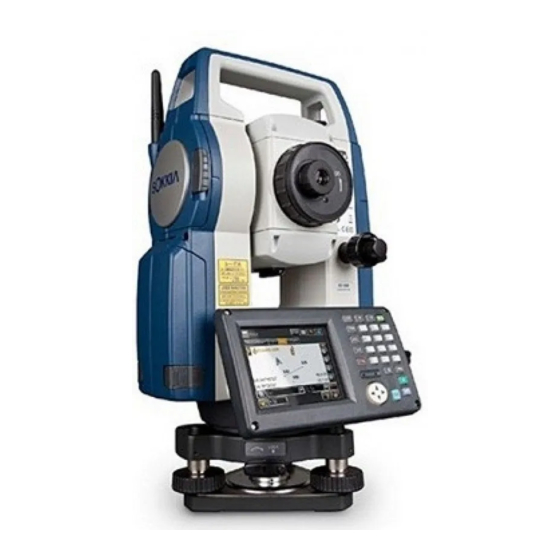
4. PRODUCT OUTLINE Parts of the Instrument Parts and functions of the instrument Handle Bluetooth antenna External interface hatch (USB port / Reset button) "10. CONNECTING TO EXTERNAL DEVICES" Instrument height mark Battery cover Display unit 7A Serial connector 7B Serial / External power source connector Circular level Circular level adjusting screws 10 Base plate... - Page 19 4. PRODUCT OUTLINE Guide light Setting-out measurement etc. can be carried out effectively using the guide light. The guide light is composed of a light that is divided into green and red sections. A poleman can ascertain the present position by checking the guide light color. green red (When seen from the objective lens side while the instrument is in the Face 1 state)
- Page 20 4. PRODUCT OUTLINE Bluetooth antenna (Models with Bluetooth module only) The Bluetooth antenna allows communication via Bluetooth wireless technology. • Handle the antenna with care. The antenna may be damaged if struck during operation or while being stored in the carrying case. Handle The carrying handle can be removed from the Handle...
-
Page 21: Mode Structure
4. PRODUCT OUTLINE Mode Structure The diagram below describes the different modes of the FX and key operations for navigating between them. ●Basic mode Observation mode (switching by tab) Top menu C “5.2 Display Menu mode Functions ”Graphic“ tab” Version C“12. -
Page 22: Bluetooth Wireless Technology
Contact your local dealer in advance. "28. REGULATIONS" • TOPCON CORPORATION is not liable for the content of any transmission nor any content related thereto. When communicating important data, run tests beforehand to ascertain that communication is operating normally. - Page 23 4. PRODUCT OUTLINE • Televisions and radios use a different frequency band to Bluetooth communications. However, even if the FX is used within proximity to the above equipment with no adverse effects with regard to Bluetooth communication, moving a Bluetooth compatible device (including the FX) closer to said equipment may result in electronic noise in sound or images, adversely affecting the performance of televisions and radios.
-
Page 24: Basic Operation
5. BASIC OPERATION Learn basic key operations here before you read each measurement procedure. Basic Key Operation Display unit Illumination key { } { } { } Target type Program mode Input mode SHIFT SHIFT FUNC Function key Luminance sensor / Microphone Power ON/OFF Power ON Press and hold: About 1... - Page 25 5. BASIC OPERATION Switching the page {FUNC} Toggle between Observation mode screen pages Inputting letters/figures α Switch between numerals and alphabetic characters {1} to {9} In alphabetic characters mode, switch between lowercase {SHIFT} + characters and upper case characters each time {SHIFT} (Press and hold) In alphabetic characters mode, switch between lowercase characters and upper case characters...
- Page 26 5. BASIC OPERATION Example: Entering "computer" (lower case) as the name of a new device 1. Tap the input mode icon in the status bar (second from bottom) until "_a" is displayed. 2. Press {7} three times. "c" is displayed. 3.
- Page 27 5. BASIC OPERATION 4. Press { }. Press {5}. "m" is displayed. 5. Continue to input letters. Press {ENT} to complete inputting. Example: selecting a reflector type (Method 1) 1. Select [EDM] in the first page of Observation mode or "EDM" in Config mode/Configuration mode.
-
Page 28: Display Functions
5. BASIC OPERATION (Method 2) 1. Select [EDM] in the first page of Measure mode or "EDM" in Config mode/Configuration mode. 2. Move to "Reflector" using { }/{TAB}. 3. Switch between Prism, Sheet, and N-Prism using { }/{ }. 4. Press {ENT} to confirm selection. Display Functions Screens can be selected/operated using the keys on the keyboard or the touch panel. - Page 29 5. BASIC OPERATION Temporarily de-activating the touch panel The touch panel can be temporarily de-activated. This is especially useful when cleaning the display. To de-activate, tap on the status bar. <Touch panel temporarily de-activated> is displayed. The touch panel cannot be operated while the above message is displayed. Press {ESC} to cancel the message and re-activate the touch panel.
- Page 30 5. BASIC OPERATION Displaying and operating screens • To close a screen, tap the cross in the top right corner, or press {ESC}. • Tabs, softkey allocations, displayed tab items, and character sizes can all be changed in accordance with user preferences. "20.
- Page 31 5. BASIC OPERATION (3) Horizontal angle Press [R/L] when allocated to the Observation mode screen to switch the display status. The capitalized letter in the softkey indicates the currently selected mode. HA-R : Horizontal angle right HA-L : Horizontal angle left "20.6 Allocating Key Functions"...
- Page 32 5. BASIC OPERATION Selecting menus To select a menu, tap the touch panel or press the relevant number key. Number Status bar Indicates the current status of the instrument. Tapping icons (1) to (8) will switch between the relevant options for that item.
- Page 33 5. BASIC OPERATION When using external battery : Level 3 Full power : Level 2 Plenty of power remains : Level 1 Half or less power remains Level 0 Little power remains. Prepare a replacement battery where available "7. USING THE BATTERY" (2) Target display Selection of target type and configuration of prism constant.
- Page 34 5. BASIC OPERATION (5) Tilt angle compensation The vertical and horizontal angles are automatically compensated for small tilt errors using the FX's dual-axis tilt sensor. This icon displays the status of this function. : Horizontal and vertical tilt angles compensated (blue) : No compensation : Only vertical tilt angle compensated (green) •...
- Page 35 5. BASIC OPERATION : Connection via RS232C cable • An arrow (e.g. ) is displayed to indicate that data transmission is in progress. A red arrow indicates that data transmission has failed and data needs to be sent again. (7) Input mode Selection of input mode Inputting numbers and symbols Inputting lower case alphabetic characters...
-
Page 36: Disk Capacity
5. BASIC OPERATION Disk Capacity Disk usage of the instrument is displayed as follows. Tap and hold disk icon in the status bar to check the detail of the disk usage. "20.7 Changing Status Bar Icons" :Less than 20% :20 to 50% :More than 50% Internal Disk Used space:... -
Page 37: Inputting Characters Using The Input Panel
5. BASIC OPERATION Inputting Characters using the Input Panel α or press and { } to display <Input Panel>. This keyboard can be used to input {SHIFT} numeric and alphabetic characters as well as symbols. Tap the icon again to close. •... -
Page 38: Inserting Usb Memory
6. INSERTING USB MEMORY • When reading/writing data, do not remove the USB memory. Procedure 1. Open the external interface hatch by sliding its button. External interface hatch 2. Insert the USB memory into the USB port 1. USB Port 1 •... -
Page 39: Using The Battery
7. USING THE BATTERY Types of power source: "23. POWER SUPPLY SYSTEM" Battery Charging The battery was not charged at the factory. Charge the battery fully before using the FX. • The charger will become rather hot during use. This is normal. •... -
Page 40: Installing/Removing The Battery
7. USING THE BATTERY 3. When charging starts, the lamp starts blinking. 4. The lamp lights when charging is finished. 5. Remove the battery and unplug the charger. • Slots 1 and 2: The charger starts charging the battery mounted first. If you place two batteries in the charger, the battery in slot 1 is charged first, and then the battery in slot 2. - Page 41 7. USING THE BATTERY PROCEDURE Mounting the battery 1. Slide down the catches on the battery cover to open. Battery cover 2. Insert the battery in the direction of the arrow on the side of the battery. • Do not insert the battery inclined. Doing so may damage the instrument or battery terminals.
-
Page 42: Setting Up The Instrument
8. SETTING UP THE INSTRUMENT • Mount the battery in the instrument before performing this operation because the instrument will tilt slightly if the battery is mounted after levelling. Centering PROCEDURE Centering with the optical plummet eyepiece 1. Make sure the legs are spaced at equal intervals and the head is approximately level. - Page 43 8. SETTING UP THE INSTRUMENT PROCEDURE Centering with the laser plummet (Option) 1. Set up the tripod and affix the instrument on the tripod head. "8.1 Centering" 2. Press {ON} to power on "9. POWER ON/OFF" The electric circular level (tilt) is displayed on the screen.
-
Page 44: Levelling
8. SETTING UP THE INSTRUMENT • Visibility of the laser spot may be affected when operating in direct sunlight. In this event, provide shade for the survey point. Levelling PROCEDURE 1. Adjust the levelling foot screws to center the survey point in the optical plummet reticle. 2. - Page 45 8. SETTING UP THE INSTRUMENT 5. Turn the instrument until the telescope is parallel to a line between levelling foot screws A and B. 6. Set the tilt angle to 0° using foot screws A and B for the X direction and levelling screw C for the Y direction.
-
Page 46: Power On/Off
9. POWER ON/OFF PROCEDURE Power ON Press { When the power is switched on, the Tilt screen is displayed. Press {ESC} to go to top menu. If "Out of range" is displayed, the instrument tilt sensor is indicating that the instrument is out of level. Level the instrument once again using circular level, then the tilt screen will be displayed. -
Page 47: Resolving Software Issues
9. POWER ON/OFF Configuring the Touch Panel When using for the first time, or after performing a cold boot, the screen for configuring the touch panel will be displayed. Follow the instructions on the screen. Tap the cross- hairs at the center of the display with the stylus pen. Tap 5 times. - Page 48 9. POWER ON/OFF Problems Powering OFF When the instrument cannot be powered OFF as normal, depress the reset button with the tip of the stylus pen. • Pressing the Reset button may result in file and folder data being lost. Reset button...
-
Page 49: Connecting To External Devices
10.CONNECTING TO EXTERNAL DEVICES The FX supports Bluetooth wireless technology, USB and RS232C for communication with data collectors etc. Read this manual in conjunction with the operator’s manual for the relevant external device. Bluetooth communication: "4.3 Bluetooth Wireless Technology" Output format and command operations: "Communication manual" •... - Page 50 10. CONNECTING TO EXTERNAL DEVICES Off: Omit the [ACK] • Setting ’(3) and (4) are for an instrument using GTS commands. 2. Select a mode for the FX in the "Bluetooth" tab. The factory setting is "Slave". Register companion devices. •...
- Page 51 10. CONNECTING TO EXTERNAL DEVICES PROCEDURE Registering Bluetooth companion devices 1. Power on the companion device. 2. Select "Bluetooth" in "Comms mode" in the "Comms setup" tab. 3. Press [LIST] to display a list of all registered devices. Register the data collectors to use in "Serial" tab and devices to use with the Dial-Up Program in "Dial-up"...
- Page 52 10. CONNECTING TO EXTERNAL DEVICES Press [Search] to search about Bluetooth devices in the immediate vicinity of the FX and display their device name and address in a list. Select a device from this list and press [OK] to add to the Link device list in step 3.
-
Page 53: Communication Between The Fx And Companion Device
10. CONNECTING TO EXTERNAL DEVICES 10.2 Communication between the FX and Companion Device • Bluetooth communication causes FX battery power to be depleted at a rate higher than that for normal operation. • Check that the companion device (data collector, computer, or cellular phone etc.) is turned on and the relevant Bluetooth settings are complete. -
Page 54: Connecting To Usb Devices
FX has two different USB ports. TOPCON CORPORATION cannot guarantee that all USB devices are compatible with the FX USB ports. • TOPCON CORPORATION cannot guarantee that all USB devices are compatible with the FX USB ports. • Use a computer WindowsXP/Vista/7 is based and USB connection is capable. - Page 55 10. CONNECTING TO EXTERNAL DEVICES Power OFF the FX. Connect the FX and computer using the USB cable. "9. POWER ON/OFF" • The computer does not need to be turned OFF before connection. 2. Press { } while pressing {ENT} to dislay a message box asking whether to boot USB mode, then press [YES].
- Page 56 10. CONNECTING TO EXTERNAL DEVICES 2. Press { } while pressing {ENT} to dislay a message box asking whether to boot USB mode, then press [NO]. The synchronous software is effective. • FX may not be displayed as <Removable Disk>. It depends on Windows settings.
-
Page 57: Connection Via Rs232C Cable
10. CONNECTING TO EXTERNAL DEVICES 10.4 Connection via RS232C cable PROCEDURE Basic cable settings 1. Connect the cable. Cables: "25. OPTIONAL ACCESSORIES" 2. Select "Comms" in Config mode. Set communication conditions in the "Comms setup" tab. Set "Comms mode" to "RS232C". 3. -
Page 58: Focussing And Target Sighting
11.FOCUSSING AND TARGET SIGHTING • When sighting the target, strong light shining directly into the objective lens may cause the instrument to malfunction. Protect the objective lens from direct light by attaching the lens hood. Observe to the same point of the reticle when the telescope face is changed. PROCEDURE 1. -
Page 59: Angle Measurement
12.ANGLE MEASUREMENT This section explains the procedures for basic angle measurement in Observation mode. • It is possible to allocate softkeys in measurement menus to suit various applications and the ways that different operators handle the instrument. "20.6 Allocating Key Functions" 12.1 Measuring the Horizontal Angle between Two Points (Horizontal Angle 0°) -
Page 60: Setting The Horizontal Angle To A Required Value (Horizontal Angle Hold)
12. ANGLE MEASUREMENT 12.2 Setting the Horizontal Angle to a Required Value (Horizontal Angle Hold) You can reset the horizontal angle to a required value and use this value to find the horizontal angle of a new target. PROCEDURE 1. Sight the first target. 2. -
Page 61: Angle Measurement And Outputting The Data
12. ANGLE MEASUREMENT 12.3 Angle measurement and Outputting the Data The following explains angle measurement and the features used to output measurement results to a computer or other external devices. "10. CONNECTING TO EXTERNAL DEVICES", Cables: "25. OPTIONAL ACCESSORIES", Output format and command operations: "Communication manual" PROCEDURE 1. -
Page 62: Distance Measurement
13.DISTANCE MEASUREMENT Perform the following settings as preparation for distance measurement in Observation mode. • Distance measurement mode • Target type • Prism constant correction value • ppm • EDM ALC "20.2 Instrument Configuration" • It is possible to allocate softkeys in measurement menus to suit various applications and the ways that different operators handle the instrument. - Page 63 13. DISTANCE MEASUREMENT PROCEDURE 1. Accurately sight the target. 2. Press [S-LEV] in observation mode. <Aiming> is displayed. Allocating [S-LEV]: "20.6 Allocating Key Functions" When [S-LEV] is pressed, a gauge indicating light intensity is displayed. • The more displayed, the greater the quantity of reflected light.
-
Page 64: Distance And Angle Measurement
13. DISTANCE MEASUREMENT 13.2 Distance and Angle Measurement An angle can be measured at the same time as distance. PROCEDURE 1. Face the FX in the direction of the target Use the sighting collimator to aim the FX and telescope toward the target. "11. -
Page 65: Distance Measurement And Outputting The Data
13. DISTANCE MEASUREMENT 13.3 Distance Measurement and Outputting the Data The following explains distance measurement and the features used to output measurement data to a computer or external devices. "10. CONNECTING TO EXTERNAL DEVICES", Communication cables: "25. OPTIONAL ACCESSORIES". Output format and command operations: "Communication manual" PROCEDURE 1. -
Page 66: Rem Measurement
13. DISTANCE MEASUREMENT 13.4 REM Measurement An REM measurement is a function used to measure the height to a point where a target cannot be directly installed such as power lines, overhead cables and bridges, etc. The height of the target is calculated using the following formula. Ht = h h2 = S sin x cot... - Page 67 13. DISTANCE MEASUREMENT 3. Sight the target and press [MEAS] to start measurement. Press [STOP] to stop the measurement. The measured distance data, vertical angle and horizontal angle are displayed. 4. Sight the object, then press [REM] to start REM measurement is started.
-
Page 68: Coordinate Measurement
14.COORDINATE MEASUREMENT By performing coordinate measurements it is possible to find the 3-dimensional coordinates of the target based on station point coordinates, instrument height, target height, and azimuth angles of the backsight station which are entered in advance. • It is possible to allocate softkeys in measurement menus to suit various applications and the ways that different operators handle the instrument. -
Page 69: Azimuth Angle Setting
14. COORDINATE MEASUREMENT 3. Select "Occupy setup" and enter instrument station coordinates,instrument height (HI) and target height (HR). 4. Press [OK] to set the input values. <Set H angle> is displayed again. 14.2 Azimuth Angle Setting Based on the instrument station coordinates and backsight station coordinates which have already been set, the azimuth angle of the backsight station is calculated. - Page 70 14. COORDINATE MEASUREMENT PROCEDURE Entering coordinates 1. Select "Backsight setup" in <Coordinate>. <Set H angle> is displayed. • <Set H angle> can also be displayed from the screen in step 4 of "14.1 Entering Instrument Station Data". 2. Select the "Key in coord" tab and enter the backsight station coordinates.
- Page 71 14. COORDINATE MEASUREMENT PROCEDURE Entering angle 1. Select "Backsight setup" in <Coordinate>. <Set H angle> is displayed. <Set H angle> can also be displayed from the screen in step 4 of "14.1 Entering Instrument Station Data". 2. Select the "Key in angle" tab and enter the desired angle in "H.ang".
-
Page 72: 3-D Coordinate Measurement
14. COORDINATE MEASUREMENT 3. Press [OK] to set the input values. <Coord. measurement> is displayed. Horizontal angle settings Azimuth (set both horizontal and azimuth angles to the same value)/H.ang (input both horizontal and azimuth angles)/None (input azimuth angle only)/0 SET (horizontal angle set to 0°) 14.3 3-D Coordinate Measurement The coordinate values of the target can be found by measuring the target based on the settings of the... - Page 73 14. COORDINATE MEASUREMENT PROCEDURE 1. Sight the target at the target point. 2. Select "Coord." in <Coordinate>. Press [MEAS] to start measurement. Press [STOP] to stop the measurement. The coordinates of the target point are displayed. Select the "Graphic" tab to display coordinates on a graph.
-
Page 74: Resection Measurement
15.RESECTION MEASUREMENT Resection is used to determine the coordinates of an instrument station by performing multiple measurements of points whose coordinate values are known. Registered coordinate data can be recalled and set as known point data. Residual of each point can be checked, if necessary. Entry Output Coordinates of... -
Page 75: Coordinate Resection Measurement
15. RESECTION MEASUREMENT 15.1 Coordinate Resection Measurement N, E, Z of an instrument station is determined by the measurement. PROCEDURE 1. Select "Resection" in <Menu>. 2. Select "NEZ" to display <Resection/Known point>. 3. Input the known point. After setting the coordinates and target height for the first known point press [NEXT] to move to the second point. - Page 76 15. RESECTION MEASUREMENT 4. Sight the first known point and press [MEAS] to begin measurement. The measurement results are displayed on the screen. • When [ANGLE] has been selected, the distance cannot be displayed. 5. Press [YES] to use the measurement results of the first known point.
- Page 77 15. RESECTION MEASUREMENT Standard deviation for the northing, easting and elevation coordinates of each point are displayed in the "Detail" tab. 8. If there are problems with the results of a point, align the cursor with that point and press [OMIT]. “OMIT”...
- Page 78 15. RESECTION MEASUREMENT • Press [ADD] in the second page when there is a known point that has not been observed or when a new known point is added. 10. Press [OK] in <Resection/result> to display <Resection/Set h angle>. 11. Select an angle mode and press [YES] to set the azimuth angle of the first known point as the backsight point and return to <Resection/Menu>.
-
Page 79: Height Resection Measurement
15. RESECTION MEASUREMENT 15.2 Height Resection Measurement Only Z (height) of an instrument station is determined by the measurement. • Known points must be measured by distance measurement only. • Between 1 and 10 known points can be measured. PROCEDURE 1. - Page 80 15. RESECTION MEASUREMENT 4. Sight the first known point and press [MEAS] to begin measurement. The measurement results are displayed on the screen. 5. If measuring two or more known points, repeat procedures 4 in the same way from the second point.
- Page 81 15. RESECTION MEASUREMENT 7. If there are problems with the results of a point, align the cursor with that point and press [OMIT]. “OMIT” is displayed to the right of the point. Repeat for all results that include problems. 8. Press [RE CALC] to perform calculation again without the point designated in step 7 The result is displayed.
- Page 82 15. RESECTION MEASUREMENT Resection calculation process The NE coordinates are found using angle and distance observation equations, and the instrument station coordinates are found using the method of least squares. The Z coordinate is found by treating the average value as the instrument station coordinates. Calculated instrument station coordinates set as hypothetical coordinates...
- Page 83 15. RESECTION MEASUREMENT Precaution when performing resection In some cases it is impossible to calculate the coordinates of an unknown point (instrument station) if the unknown point and three or more known points are arranged on the edge of a single circle.
-
Page 84: Setting-Out Measurement
16.SETTING-OUT MEASUREMENT Setting-out measurement is used to set out the required point. The difference between the previously input data to the instrument (the setting-out data) and the measured value can be displayed by measuring the horizontal angle, distance or coordinates of the sighted point. -
Page 85: Distance Setting-Out Measurement
16. SETTING-OUT MEASUREMENT Guide light status and meaning Indication for positioning target during setting-out measurement Light status Meaning Increased flashing speed (From position of poleman) Move target toward FX Decreased flashing speed (From position of poleman) Move target away from FX Fast flashing Target is at correct distance (From position of poleman) Move target left... - Page 86 16. SETTING-OUT MEASUREMENT PROCEDURE 1. Select "Setting out" in <Menu> to display <Setting out>. 2. Select "Occupy setup" to display <Occupy setup>. Enter data for the instrument station and press [OK] to move to Backsight setup. "14.1 Entering Instrument Station Data" 3.
- Page 87 16. SETTING-OUT MEASUREMENT 4. Select "SO data setting" In <Setting out> to display <SO data setting>. In the distance mode that conforms to your measurement requirements, enter the included angle between the reference point and the setting-out point in "SO.H.ang", and the distance (slope distance, horizontal distance or height difference) from the instrument station to the position to be set out in "SO.Sdist".
- Page 88 16. SETTING-OUT MEASUREMENT 6. Position the target on the line of sight and press Arrows indicate direction to move [MEAS] to begin distance measurement. The distance and direction to move the target until the setting out point is located is displayed on the FX.
- Page 89 16. SETTING-OUT MEASUREMENT 7. Move the target until the distance to the setting- out point reads 0m. When the target is moved within the allowed range, all distance and position arrows are displayed. 8. Press {ESC} to return to <Setting out>. Set the next setting out point to continue setting out measurement.
-
Page 90: Coordinates Setting-Out Measurement
16. SETTING-OUT MEASUREMENT 16.3 Coordinates Setting-out Measurement After setting the coordinates for the point to be set out, the FX calculates the setting-out horizontal angle and horizontal distance. By selecting the horizontal angle and then the horizontal distance setting-out functions, the required coordinate location can be set out. •... - Page 91 16. SETTING-OUT MEASUREMENT 3. Select "Key in coord" in <Setting out>. Record all the setting-out points (includes setting-out points you will measure from now). Press [ADD] to record new data. • Press [DEL] in the second page to delete the selected setting out point.
- Page 92 16. SETTING-OUT MEASUREMENT 5. Position the target on the line of sight and press [MEAS] to begin distance measurement. The distance and direction to move the target until the setting out point is located is displayed on the FX. The sighting point measurement results (currently installed position of the target) are displayed.
-
Page 93: Rem Setting-Out Measurement
16. SETTING-OUT MEASUREMENT 6. Press {ESC} to return to <Key in coord>. Set the next setting out point to continue setting out measurement. 16.4 REM Setting-out Measurement To find a point where a target cannot be directly installed, perform REM setting-out measurement. "13.4 REM Measurement"... - Page 94 16. SETTING-OUT MEASUREMENT 4. Enter values and press [OK] in step 3 to display the screen at right. 5. Sight the target and press [MEAS]. Measurement begins and the measurement results are displayed. 6. Press [REM] to start REM measurement. Arrows indicate direction to move The distance (height difference) and direction to move the target until the sighting point and setting...
- Page 95 16. SETTING-OUT MEASUREMENT • Press [CNFG] to set setting out accuracy. When the position of the target is within this range both arrows will be displayed to indicate that the target position is correct. 7. Press {ESC} to return to <SO data setting>.
-
Page 96: Offset Measurement
17.OFFSET MEASUREMENT Offset measurements are performed in order to find a point where a target cannot be installed directly or to find the distance and angle to a point which cannot be sighted. • It is possible to find the distance and angle to a point you wish to measure (target point) by installing the target at a location (offset point) a little distance from the target point and measuring the distance and angle from the survey point to the offset point. - Page 97 17. OFFSET MEASUREMENT 2. Select "Offset" in <Menu> to display . 3. Select "Occupy setup" to display <Occupy setup>. Enter data for the instrument station and press [OK] to move to Backsight setup. "14.1 Entering Instrument Station Data" 4. Set the azimuth angle for the backsight station. Press [OK] to return to <Offset>.
- Page 98 17. OFFSET MEASUREMENT 6. Sight the offset point and press [MEAS] in the screen of step 3 to start measurement. Press [STOP] to stop the measurement. The measurement results are displayed. • Press [HVD/nez] to switch results for the target point between distance/angle values and coordinate/elevation values.
-
Page 99: Angle Offset Measurement
17. OFFSET MEASUREMENT 17.2 Angle Offset Measurement Sighting the direction of the target point to find it from the included angle. Install offset points for the target point on the right and left sides of and as close as possible to the target point and measure the distance to the offset points and the horizontal angle of the target point. - Page 100 17. OFFSET MEASUREMENT 3. Sight the offset point and press [MEAS] to start measurement. Press [STOP] to stop the measurement. 4. Sight the target point and press [H.ANG]. Results for target point • Press [HVD/nez] to switch results for the target point between distance/angle values and coordinate/elevation values.
-
Page 101: Two-Distance Offset Measurement
17. OFFSET MEASUREMENT 17.3 Two-distance Offset Measurement By measuring the distances between the target point and the two offset points. Install two offset points (1st target and 2nd target) on a straight line from the target point, observe the 1st target and 2nd target, then enter the distance between the 2nd target and the target point to find the target point. - Page 102 17. OFFSET MEASUREMENT PROCEDURE 1. Install two offset points (1st target, 2nd target) on a straight line from the target point and use the offset points as the target. 2. Select "Offset" in <Menu> to display <Offset>. Select "5.Offset2D". 3. Press [CNFG] and input the distance from the 2nd target to the target point in "Offset dist.".
- Page 103 17. OFFSET MEASUREMENT 5. Sight the 2nd target and press [MEAS] to start measurement. Press [STOP] to stop the measurement. The measurement results are displayed. 6. Press [YES] to display results for the target point. Press [HVD/nez] to switch results for the target point between distance/angle values and coordinate/elevation values.
-
Page 104: Missing Line Measurement
18.MISSING LINE MEASUREMENT Missing line measurement is used to measure the slope distance, horizontal distance, and horizontal angle to a target from the target which is the reference (starting point) without moving the instrument. • It is possible to change the last measured point to the next starting position. •... - Page 105 18. MISSING LINE MEASUREMENT 2. Sight the starting position, and press [MEAS] to start measurement. Press [STOP] to stop measurement. • When measurement data already exists the screen of step 3 is displayed and measurement starts. 3. Sight the next target and press [MLM] to Results for measurement between starting begin observation.
-
Page 106: Changing The Starting Point
18. MISSING LINE MEASUREMENT 18.2 Changing the Starting Point It is possible to change the last measured point to the next starting position. PROCEDURE 1. Observe the starting position and target following steps 1 to 3 in "18.1 Measuring the Distance between 2 or more Points". - Page 107 18. MISSING LINE MEASUREMENT Press [YES] in the confirmation message window. • Press [NO] to cancel measurement. 3. The last target measured is changed to the new starting position. 4. Perform missing line measurement following steps 3 to 4 in "18.1 Measuring the Distance between 2 or more Points".
-
Page 108: Surface Area Calculation
19.SURFACE AREA CALCULATION You can calculate the area of land (slope area and horizontal area) enclosed by three or more known points on a line by inputting the coordinates of the points Input Output S (horizontal area and slope Coordinates: P1 (N1, E1, Z1) Surface area: area) - Page 109 19. SURFACE AREA CALCULATION PROCEDURE Surface area calculation by measuring points 1. Select "Area calc." in <Menu> 2. Press [OBS] to display <Area calculation/ measurement>. Sight the first point on the line enclosing the area, and press [MEAS]. Measurement begins and the measured values are displayed.
- Page 110 19. SURFACE AREA CALCULATION 3. The measurement results are displayed. Press [YES] to confirm.The value of point 1 is set in "Pt_01". 4. Repeat steps 2 to 3 until all points have been measured. Points on an enclosed area are observed in a clockwise or counterclockwise direction.
- Page 111 19. SURFACE AREA CALCULATION 5. Press [CALC] to display the calculated area. 6. Press [OK] to return to <Area/key in coord.>. Press {ESC} or tap the cross in the top-right corner to quit area calculation.
-
Page 112: Changing The Settings
20.CHANGING THE SETTINGS This section explains the contents of parameter settings in Basic mode and how to change these settings. Each item can be changed to meet your measurement requirements. <Configuration> can be accessed by pressing the "CONFIG" icon in <Top>. The following chapters provide details of items in Configuration mode. - Page 113 20. CHANGING THE SETTINGS Tilt crn (tilt correction) Yes (H,V)*, No, Yes (V) Tilt error: No action*/Go to Tilt screen Coll.crn. (collimation correction) No, Yes* C&R crn.: No, Yes(K=0.142),Yes(K=0.20)* V manual: No*, Yes V.obs (vertical angle display method) :Zenith*, Horiz., Horiz ±90 Coordinates: N-E-Z*, E-N-Z Sea level crn.
- Page 114 20. CHANGING THE SETTINGS Collimation correction The FX has a collimation correction function that automatically corrects horizontal angle errors caused by horizontal axis and leveling axis errors. Sea level correction The FX calculates horizontal distance using slope distance values. As this horizontal distance does not take height above sea level into consideration, performing spherical correction is recommended when measuring at high altitudes.
-
Page 115: Instrument Configuration
20. CHANGING THE SETTINGS 20.2 Instrument Configuration Items set and options (*: Factory setting) Power off No/5min./10min./15min./30min.* Backlight (Reticle On) : 0 to 8 (1*) (Brightness level on pressing { Backlight (Normal) 0 to 8 / Auto (Auto*) Backlight Off No*/30sec/1min./5min./10min. - Page 116 20. CHANGING THE SETTINGS Adjusting backlight brightness/turning the reticle illumination and key backlight ON/OFF Pressing { } switches the brightness level of the backlight in conjunction with the ON/OFF status of the reticle illumination/key backlight. When the FX is powered ON the brightness level is set to "Backlight (Normal)". "Backlight (Normal)"...
-
Page 117: Edm Settings
20. CHANGING THE SETTINGS EDM ALC Set the light receiving status of the EDM. While carrying out continuous measurement, set this item according to the measurement conditions. • When EDM ALC is set to "Free," the instrument’s ALC will be automatically adjusted if an error occurs as a result of the amount of light received. - Page 118 20. CHANGING THE SETTINGS • The setting for "Fine AVG" distance measurement mode can be increased/decreased using the [ + ]/[ - ] softkeys. • Target information can be edited and recorded. "PROCEDURE Recording and editing target information" • "Prism constant" will not be displayed when "N-Prism" is selected in "Reflector". •...
- Page 119 20. CHANGING THE SETTINGS Atmospheric correction factor The velocity of the light beam used for measurement varies according atmospheric conditions such as temperature and air pressure. Set the atmospheric correction factor when you wish to take this influence into account when measuring. •...
- Page 120 20. CHANGING THE SETTINGS Humidity h Humidity h • If the weather correction is not required, set the ppm value to 0. PROCEDURE Recording and editing target information The [LIST] softkey is displayed when either "Reflector" or "Prism const." is selected in the "EDM" tab of <EDM configurations>.
-
Page 121: Allocating User-Defined Tabs
20. CHANGING THE SETTINGS 2. To edit a target, select the desired target and press [EDIT]. <Reflector/edit> is displayed. Select/input relevant information for the target. Reflector: Prism/Sheet/N-Prism Const.: -99 to 99 mm • When selecting "N-Prism" in "Reflector", prism constant correction values are set to "0" automatically. - Page 122 20. CHANGING THE SETTINGS • Setting out Coord. Factory settings User-definable tabs Graph1 Graph2 • Graphic tab cannot be deleted. PROCEDURE Allocating tabs 1. Select "Customize" to display <Customize/Select screen>. Select the measurement mode in which you want to allocate a tab. Select "Tab page".
-
Page 123: Customizing Screen Controls
20. CHANGING THE SETTINGS 2. Use the softkeys ([ADD], [DEL] etc.) in <Customize tab page> to allocate the desired tab page layout. • Press [ADD] to add the selected tab at the right- hand side of the screen. • Press [INS] in the second page to insert the selected tab in front of the current tab. - Page 124 20. CHANGING THE SETTINGS PROCEDURE Customizing screen controls 1. Select "Customize" to display <Customize/Select screen>. Select the measurement mode in which you want to customize screen controls. Select "Control". 2. Press [ADD] to add a control drop-down list. • Press [DEL] to delete the selected control. •...
-
Page 125: Allocating Key Functions
20. CHANGING THE SETTINGS 4. Press [CNFG] to set the size, thickness, color and spacing of the font. 5. Repeat steps 2 to 4 to customize more screen controls. 6. Press [OK] to finish customizing screen controls. The modifications are stored in memory and <Customize>... - Page 126 20. CHANGING THE SETTINGS 3. "SHV" and "NEZ" tabs of <Set out Coords> Page 1 [ OK ] [ --- ][CNFG] [MEAS] Page 2 [ --- ] [ --- ] [ --- ] [ --- ] Page 3 [ --- ] [ --- ] [ --- ] [ --- ] The following functions can be allocated to the softkeys.
- Page 127 20. CHANGING THE SETTINGS PROCEDURE Allocating a softkey 1. Select "Customize" to display <Customize/Select screen>. Select the measurement mode in which you want to allocate a softkey. Select "Softkey". 2. Select the desired tab. All softkeys currently allocated to each page of that tab are displayed. 3.
-
Page 128: Changing Status Bar Icons
20. CHANGING THE SETTINGS 4. Select the desired softkey from <Softkey list> to allocate to the position specified in step 3. 5. Repeat steps 3 to 4 to perform further key allocations. 6. Press [OK] to finish allocating keys. The allocated keys are stored in memory and <Customize>... - Page 129 20. CHANGING THE SETTINGS PROCEDURE Changing icon allocations 1. Select "Customize" to display <Customize/Select screen>. Select "Status bar". 2. Select the icon position (in the status bar) you wish to re-allocate by tapping or using arrow key. A blue arrow will indicate the selected position. 3.
-
Page 130: Units
20. CHANGING THE SETTINGS 20.8 Units Items set and options (*: Factory setting) Temperature: Celsius*/Fahrenheit Pressure: hPa*/mmHg/InchHg Angle: Degree (DDD.MMSS)*/Gon/Mil Distance: Meter*/Feet/Inch Feet (only displayed when "Feet" or "Inch" selected above): International*/US • OS rounds off the value input by the digit of less than 0.004 feet/0.017 inch. Inch (Fraction of an inch) “Fraction of an inch”... -
Page 131: Changing Password
20. CHANGING THE SETTINGS 20.9 Changing Password Setting a password allows you to protect important information such as measurement data addresses. No password was set when the FX was shipped. When setting a password for the first time, leave the "Old password"... -
Page 132: Restoring Default Settings
20. CHANGING THE SETTINGS 20.10 Date and Time Items set Date: Manually input date or select from the drop-down calendar by tapping Time: Manually input time or set using [ Pressing {SPACE} will increment the selected section by 1. Date and Time The FX includes a clock/calendar function. -
Page 133: Warning And Error Messages
21.WARNING AND ERROR MESSAGES The following is a list of the error messages displayed by the FX and the meaning of each message. If the same error message is repeated or if any message not shown below appears, the instrument has malfunctioned. - Page 134 21. WARNING AND ERROR MESSAGES Input over 3 letters ! The input password consists of less than 3 characters. Input a password at least 3 characters in length. Need base pt. obs During REM measurement, the observation of the target was not completed normally. Reset and sight the prism and perform measurement again.
- Page 135 21. WARNING AND ERROR MESSAGES Tilt over range !! The tilt angle exceeds the tilt angle compensation range of the sensor. Sight again within ±1'. Time out !! Measurement is not carried out in the allotted time. Reset and sight the prism and perform measurement again.
-
Page 136: Checks And Adjustments
22.CHECKS AND ADJUSTMENTS FX is a precision instrument that requires fine adjustments. It must be inspected and adjusted before use so that it always performs accurate measurements. • Always perform checking and adjustment in the proper sequence beginning from "22.1 Circular Level"... -
Page 137: Tilt Sensor
22. CHECKS AND ADJUSTMENTS 22.2 Tilt Sensor If the tilt angle shown on the display shifts from tilt angle 0° (zero point), the instrument is not correctly levelled. This will adversely affect angle measurement. Perform the following procedure to cancel the tilt zero point error. PROCEDURE Checking and adjusting 1. - Page 138 22. CHECKS AND ADJUSTMENTS 5. Press [OK] and rotate the top of the instrument and telescope 180° from the current position. 6. Wait a few seconds for the screen to stabilize, then read the automatically compensated angles X2 and Y2. 7.
- Page 139 22. CHECKS AND ADJUSTMENTS 14. In this state, the following offset values (tilt zero point error) are calculated. Xoffset = (X3+X4)/2 Yoffset = (Y3+Y4)/2 When both offset values fall within the range ±10", adjustment is completed. Press {ESC} to return to <Instrument constants>. If one of the offset values (Xoffset, Yoffset) exceeds ±10", repeat the check and adjustment procedures from the beginning.
-
Page 140: Collimation
22. CHECKS AND ADJUSTMENTS 22.3 Collimation With this option you can measure collimation error in your instrument so that the FX can correct subsequent single face observations. To measure the error, make angular observations using both faces. PROCEDURE 1. Select "Inst. cons." in <Configuration>. 2. -
Page 141: Reticle
22. CHECKS AND ADJUSTMENTS 5. Press [YES] to set the constant. • Press [NO] to discard the data and return to the screen in step 3. 22.4 Reticle With this option you can check the perpendicularity of the reticle and the horizontal/vertical positions of reticle lines. - Page 142 22. CHECKS AND ADJUSTMENTS 2. Install a target at a point about 100m in the horizontal direction from the FX. 3. While the Observation mode screen is displayed and the telescope is in face left, sight the center of the target and read out the horizontal angle A1 and the vertical angle B1.
-
Page 143: Optical Plummet
22. CHECKS AND ADJUSTMENTS 22.5 Optical Plummet • Be careful that the tightening tension is identical for all the adjusting screws. • Also, do not over-tighten the adjusting screws as this may damage the circular level. PROCEDURE Checking 1. Carefully level the FX and center a survey point precisely in the reticle of the optical plummet. -
Page 144: Additive Distance Constant
22. CHECKS AND ADJUSTMENTS 5. Use the 4 adjusting screws of the optical plummet 1 (2) to adjust the remaining half of the deviation as shown below. When the survey point is on the lower (upper) part of the illustration: Loosen the upper (lower) adjusting screw slightly, and tighten the upper (lower) adjusting screw the same amount to move the survey point to a point... - Page 145 22. CHECKS AND ADJUSTMENTS PROCEDURE Check 1. Find an area of flat ground where two points 100m apart can be selected. Set up the Instrument at point A and the reflective prism at point B. Establish a point C half way between points A and B.
-
Page 146: Laser Plummet (Option)
22. CHECKS AND ADJUSTMENTS 22.7 Laser Plummet (Option) Checks and adjustments are performed using an adjustment target. Make an enlarged or reduced copy of it. PROCEDURE Check 1. Level the instrument and emit the laser plummet beam. 8.2 Levelling 2. Rotate the upper part horizontally and place a target so that it is aligned with the center of the circle created by the rotating laser plummet beam. - Page 147 22. CHECKS AND ADJUSTMENTS 4. Turn the upper part of the instrument horizontally through 180° and note the new position (y) of the laser beam. Desired final position Adjustment will bring the laser beam to a point midway along a line drawn between these two positions.
- Page 148 22. CHECKS AND ADJUSTMENTS 8. Turn the upper part of the instrument horizontally and check that the laser beam is now aligned with the target center. 9. Re-attach the laser plummet adjustment cap. • Tightening each of the fine adjustment screws moves the laser plummet beam in the directions shown below.
-
Page 149: Power Supply System
23.POWER SUPPLY SYSTEM Operate your FX with the following combinations of power equipment. • When using BDC60/61 and EDC139, mount the BDC70 in place to maintain the balance of the instrument. • Never use any combination other than those indicated below. If you do, the FX could be damaged. Those indicated by * are standard accessories. -
Page 150: Target System
24.TARGET SYSTEM • Because all SOKKIA reflecting prisms and accessories have standardized screws, it is possible to combine these prisms, accessories, etc. according to your objectives. • The following are all special accessories (sold separately). • Because these targets (*2) are coated with fluorescent paint, they reflect when there is little light. •... - Page 151 24. TARGET SYSTEM 2-point target (2RT500-K) This target is used for two-distance offset measurement. Prism constant: 0 Instrument height adaptor (AP41) This device is used to adjust the height of the target. Make sure that the instrument height “236” (mm) is displayed in the instrument height adjustment window.
-
Page 152: Optional Accessories
25.OPTIONAL ACCESSORIES The following are optional accessories which are sold separately from the FX. Power supply and target optional accessories: "23. POWER SUPPLY SYSTEM", "24. TARGET SYSTEM". Plumb bob The plumb bob can be used to set up and center the instrument on days when there is little wind. - Page 153 25. OPTIONAL ACCESSORIES Diagonal eyepiece (DE27) The diagonal eyepiece is convenient for DE27 observations near the nadir and in narrow spaces. Magnification: 30X After removing the handle from the FX loosen the attachment screw to remove the telescope eyepiece. Then screw the diagonal lens into place. Handle removal method: "4.1 Parts of the Instrument "Handle""...
-
Page 154: Specifications
26.SPECIFICATIONS Except where stated, the following specifications apply to all FXs. Telescope Length 171mm Aperture 45mm (1.8 inch) (EDM: 48mm (1.9 inch)) Magnification Image Erect Resolving power: FX-101/102/103/105: 2.5" FX-107: 3.5" Field of view 1°30' (26m/1,000m) Minimum focus 1.3m (4.3ft) Focussing screw 1 speed Reticle illumination... - Page 155 26. SPECIFICATIONS Distance measurement Measuring method Coaxial phase-contrast measuring system Signal source Red laser diode 690nm Class 3R (IEC60825-1 Ed. 2.0: 2007/FDA CDRH 21CFR Part1040.10 and 1040.11 (Complies with FDA performance standards for laser products except for deviations pursuant to Laser Notice No.50, dated July 26, 2001.)) (When the prism or reflective sheet is selected in Config mode as target, the output is equivalent to Class 1)
- Page 156 26. SPECIFICATIONS ±(3 + 2ppm X D) mm (0.3 to 200m) ±(5 + 10ppm X D) mm (over 200 to 350m) ±(10 + 10ppm X D) mm (over 350 to 500m) Rapid measurement: ±(6 + 2ppm X D) mm (0.3 to 200m) ±(8 + 10ppm X D) mm (over 200 to 350m) ±(15 + 10ppm X D) mm (over 350 to 500m) (Reflectorless (Gray))
- Page 157 26. SPECIFICATIONS Guide Light Light source LED (red 626 nm/green 524 nm) Distance 1.3 to 150m Visible range Right and Left/Upward and Downward: ± 4° (7m/100m) Resolving power at center area (width) 4’ (about 0.12/100m) Brightness 3 levels (bright/normal/dim) Internal memory Capacity 500 MB (includes memory for program files) External memory...
- Page 158 26. SPECIFICATIONS Battery (BDC70) Nominal voltage: 7.2V Capacity: 5,240mAh Dimensions: 38 (W) x 70 (D) x 40 (H) mm Weight: about 195g Charger (CDC68) Input voltage: AC100 to 240V Charging time per battery (at 25°C): BDC70: about 5.5 hours (Charging can take longer than the times stated above when temperatures are either especially high or low.) Charging temperature range: 0 to 40°C Storage temperature range: -20 to 65°C...
- Page 159 26. SPECIFICATIONS Instrument height: 192.5 mm from tribrach mounting surface 236mm +5/-3mm from tribrach bottom Size (with handle) Display on one side: 191 (W) X 174 (D) X 348 (H) mm Display on both sides: 191 (W) X 190 (D) X 348 (H) mm Weight (with handle and battery) 5.7kg (12.3 lb) No direct sunlight for using high temperatures of 50 to 60°C (122 to 140°F).
-
Page 160: Explanations
27.EXPLANATIONS 27.1 Manually Indexing the Vertical Circle by Face Left, Face Right Measurement The 0 index of the vertical circle of your FX is almost 100% accurate, but when it is necessary to perform particularly high precision angle measurements, you can eliminate any inaccuracy of the 0 index as follows. -
Page 161: Regulations
20cm and more between the radiator and person’s body (excluding extremeties: hands, wrists, feet and ankles). Declaration of Conformity Model Number: FX series Trade Name: TOPCON CORPORATION Manufacture Name: TOPCON CORPORATION Address: 75-1, Hasunuma-cho, Itabashi-ku, Tokyo, 174-... - Page 162 28. REGULATIONS Region/ Directives/ Labels/Declarations Country Regulations Perchlorate California, Material U.S.A. (CR Lithium Battery) California Recycling and NY, Batteries U.S.A. This Class A digital apparatus meets all requirements of Canadian Interference-Causing Equipment Regulations. Cet appareil numérique de la Class A respecte toutes les exigences du Règlement sur le matériel brouilleur du Canada.
- Page 163 Directive 1999/5/EC. R&TTE-Class Please inquire below if you wish to receive a copy of Topcon's Declaration of Conformity. Topcon Europe Positioning B.V. Essebaan 11, 2908 LJ Capelle a/d IJssel,...
- Page 164 28. REGULATIONS Region/ Directives/ Labels/Declarations Country Regulations Australia C-Tick 23316 China SRRC Chinese China Environment al Directive...
-
Page 165: Index
29.INDEX ACK mode ..........................41 Adjusting backlight brightness/turning the reticle illumination and key backlight ON/OFF ..108 Atmospheric correction factor ....................111 Automatic tilt angle compensation mechanism ................ 105 Bluetooth connections ........................ 41 Bluetooth device address......................44 Cold boot............................ 39 Collimation correction ...................... - Page 166 Please see the attached address list or the following website for contact addresses. GLOBAL GATEWAY http://global.topcon.com/ © 2012 TOPCON CORPORATION ALL RIGHTS RESERVED...
Need help?
Do you have a question about the Sokkia FX Series and is the answer not in the manual?
Questions and answers
не работает активный экран
The active screen on the Topcon Sokkia FX Series may not be working due to the need for touch panel configuration. When using the device for the first time or after a cold boot, the screen for configuring the touch panel appears. The user must follow the instructions and tap the crosshairs at the center of the display with the stylus. If the screen is unresponsive, it may require recalibration or troubleshooting.
This answer is automatically generated