
Related Manuals for Enerdrive ePRO Plus

Summary of Contents for Enerdrive ePRO Plus
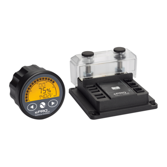
- Page 1 Owner’s Manual High Precision Module Battery Monitor Enerdrive ePRO Plus Battery Monitor Owner’s Manual (Rev. 1.03) January 2019...
- Page 2 Notice of Copyright ePRO Plus owner’s manual © 2019 Enerdrive Pty Ltd. All rights reserved. No part of this document may be reproduced in any form or disclosed to third parties without the express written permission of Enerdrive 11 Millennium Place, Tingalpa, Queensland, Australia 4173. Enerdrive reserves the...
-
Page 3: Table Of Contents
INTRODUCTION ....................5 1.1 General ............................5 1.2 Box Contents .........................5 1.3 Why A Battery Should Be Monitored ................5 1.4 ePRO Plus Highlights ......................6 1.5 CDU Display And Control Overview ................6 1.6 Active Shunt Status Indicator ..................7 QUICKSTART ....................9 2.1 General ............................9 2.2 Setup wizard .........................9... - Page 4 11. WARRANTY CONDITIONS ................37 12. DECLARATION OF CONFORMITY ..............38 13. APPENDIX 1: ....................39 Measuring The Midpoint Voltage Of A 24V Or 48V Battery Bank ......39 Wiring .............................39 Practical Information .........................41 Page 4 Enerdrive ePRO Plus Battery Monitor Owners Manual (Rev. 1.03)
-
Page 5: Introduction
Besides o ering an accurate state of charge indication, the ePRO Plus will also help users how to get the best service life out of the battery bank. The service life of batteries will be negatively a ected by excessive deep discharging, under- or overcharging, excessive charge- or discharge currents and/or high temperatures. -
Page 6: Epro Plus Highlights
The ePRO Plus is compatible with lead based and Lithium (LiFePO4) based batteries. The ePRO Plus can monitor up to three battery banks. The inputs for battery bank 2 and 3 can also be con gured for other purposes, like mid-point voltage measurement, key switch input or back light control. -
Page 7: Active Shunt Status Indicator
Please see the image below for the location of the status indicator: The status indicator has multiple operating modes, distinguished each by colour or ash interval. Please see the table below for an overview of the operating modes: www.enerdrive.com.au Page 7... - Page 8 Main battery empty, recharge now (SoC Slow < 30 %) Fast Error Orange Fast Initializing Status ash interval times are 2 seconds for ‘Slow’ and 0.5 seconds for ‘Fast’ Page 8 Enerdrive ePRO Plus Battery Monitor Owners Manual (Rev. 1.03)
-
Page 9: Quickstart
Plus up and running. It assumes that the enclosed installation guide has been followed carefully and that the ePRO Plus is powered up for the rst time. After this the Setup wizard will start automatically. If the Setup wizard does not start and the ePRO Plus will jump to the normal operating mode after power up, it has already been con gured before. - Page 10 Functions F2 and F3 (see chapter 6.2 and 6.3). After the Setup wizard has been completed, the ePRO Plus will take a few seconds to analyze your battery and estimate the nominal battery voltage as well as the current State of Charge (%).
- Page 11 48V (24 cells) 48V (16 cells) Once the ePRO Plus shows the estimated state of charge value, it is now ready for use! Over time, it will keep on learning your battery and the estimated state of charge will become increasingly more accurate.
-
Page 12: Normal Operating Mode
3. NORMAL OPERATING MODE 3.1 Overview Of Parameter Readouts In normal operating mode, the ePRO Plus can show you a wide range of important battery parameters. Each parameter can be accessed by pressing the left or right arrow keys. The main and most important parameter is the State of Charge (SoC) in %. - Page 13 Main battery power (W) Shows the power draw from the main battery (negative sign) or the power ow into the battery (positive sign). This reading is turned o by default and can be turned on in Function F9.2. www.enerdrive.com.au Page 13...
-
Page 14: Display Messages
°C, but it can be set to °F as well in Function F10.3. 3.2 Display Messages The ePRO Plus can show a number of di erent status messages on the display. These will vary from advisory- to error messages. Please see the table below for the available messages Table 4... -
Page 15: Synchronization
The number inside the battery icon indicates to which battery the message applies 3.3 Synchronization The ePRO Plus is a true next generation battery monitor that does not speci cally require a full synchronization before you can actually use it (except for LiFePO4 batteries). The smart internal algorithms can already estimate the state of charge by performing a short battery analysis at start up. -
Page 16: Status Menu
4. STATUS MENU The Status menu is a read only menu that shows the current status of a number of ePRO Plus items. This menu can be accessed by the following sequence: When the Status menu is entered, you can use the left and right arrow keys to browse through the di erent status items. - Page 17 Hours since charged. Shows the number of hours since the battery has last been charged. S 4.4 Hours since synchronized. Shows the number of hours since the battery monitor has last been synchronized with the main battery. www.enerdrive.com.au Page 17...
-
Page 18: History Menu
5. HISTORY MENU The History menu is a read only menu that shows the ePRO Plus’s History data. History data are special events that are stored in internal memory. This menu can be accessed by the following sequence: When the History menu is entered, you can use the left and right arrow keys to browse through the di erent History items. -
Page 19: Function Setup Menu
6. FUNCTION SETUP MENU In the Function setup menu, your ePRO Plus can be adjusted further to t your needs. This menu can only be entered after you have nished the initial Setup wizard. The following sequence gives access to the Function menu: When the Function setup menu is entered, you can use the left and right arrow keys to browse through the di erent Functions. - Page 20 Range: see table 8 Table 8 Battery bank name Description Bank 1 Battery bank 1 Bank 2 Battery bank 2 Bank 3 Battery bank 3 Main Main battery bank Page 20 Enerdrive ePRO Plus Battery Monitor Owners Manual (Rev. 1.03)
-
Page 21: Battery Bank 2 Properties
Battery bank 2 function. Set the function for the battery bank 2 (+B2) input. Default: DISABLE Range: see table 9 Table 9 Function Description DISABLE Input is not used. AUX.BAT Use input for monitoring an additional battery bank. www.enerdrive.com.au Page 21... -
Page 22: Battery Bank 3 Properties
Range: see table 9 F3.1 Battery bank 3 type (will only show when F3.0 is set to AUX.BAT). Choose the chemistry type of your battery. Default: AGM Range: see table 7 Page 22 Enerdrive ePRO Plus Battery Monitor Owners Manual (Rev. 1.03) -
Page 23: System Properties
Step size: 100h 6.5 Alarm Properties The ePRO Plus o ers four independent con gurable alarms. This o ers great exibility for the installer. Whether you wish to con gure four completely di erent alarm types, or trigger an individual alarm on for example four di erent State of Charge values, there are almost limitless possibilities. - Page 24 High discharge current. When the (bank1) discharge current exceeds the On value, the associated alarm will be activated. When the charge current falls below the O value, this alarm will be deactivated again. Page 24 Enerdrive ePRO Plus Battery Monitor Owners Manual (Rev. 1.03)
- Page 25 V.HiGH 16.0V 15.5V High battery voltage. When the voltage (bank2) rises above the On value, the associated alarm will be activated. When the voltage falls below the O value, this alarm will be deactivated again. www.enerdrive.com.au Page 25...
- Page 26 The Alarms 2, 3 and 4 can be con gured in respectively Functions F6.0 - F6.7, F7.0 – F7.7 and F8.0 – F8.7. Each Function range contains the same settings options as for Alarm 1 (F5.0 – F5.7). Page 26 Enerdrive ePRO Plus Battery Monitor Owners Manual (Rev. 1.03)
-
Page 27: Display Properties
Auto hide parameter. The default setting will allow the bottom parameter to only show for 120 seconds after the ePRO Plus has been accessed. This will keep the display clean under normal conditions, which might be preferred by less technical end users. -
Page 28: Global Properties
(0.1 – 0.3V), which is the last stage of the charging process. The default value can be multiplied by 2 or 4 if respectively 24V or 48 systems are connected to the ePRO Plus. Default: 13.2V Range: 7.0 –... - Page 29 Bank 3 series cell count (will only show when F3.0 is set to AUX.BAT). Allows you to edit the number of internal cells of your used batteries, that was automatically determined after completing the Setup Wizard. See table 2 in chapter 2.2 for more information. Default: dynamic Range: 2 – 30 Step size: 1 www.enerdrive.com.au Page 29...
- Page 30 Default: 1 Range: 0 – 2 Step size: 1 All changed Function settings remain in the ePRO Plus’s internal memory. Even when the supply voltage has been interrupted. This also applies to the stored Status and History items. Page 30...
-
Page 31: Reset Menu
1.3 Factory Reset. This reset item can be used to reset all Function, Status and History values to factory default values. After a factory reset, the ePRO Plus restart to the Setup Wizard again. www.enerdrive.com.au... -
Page 32: Lock Menu
8. LOCK MENU In the Lock menu, you can lock or unlock the Function setup and Reset menu of the ePRO Plus by entering a pin code. Locking these menus can be useful to prevent untrained personnel for making any changes to the instrument’s settings. This menu can be accessed by the following sequence: In the Reset menu, only Reset Alarms (r1.0) will remain available when the unit is locked... -
Page 33: Troubleshooting Guideline
Display returns ‘- -.-‘ in temperature readout • Connection with the temperature sensor is lost. Check sensor cable. The monitor resets all the time • Check wiring for corrosion or bad contacts • Battery might be at or defective www.enerdrive.com.au Page 33... - Page 34 In this case, Function A01 can be set to ‘LEGACY’ and Function A02 approx. 0.2V-0.3V below the absorption voltage. Page 34 Enerdrive ePRO Plus Battery Monitor Owners Manual (Rev. 1.03)
-
Page 35: Technical Specifications
10. TECHNICAL SPECIFICATIONS Parameter ePRO Plus Supply voltage range 7..70Vdc Supply current (@ 12V/ 24V/48V) 10mA / 6mA / 5mA Input voltage range main battery (+B1) 7..70Vdc Input voltage range second and third battery (+B2, +B3) 1..70Vdc Input current range -600..+600A... - Page 36 Please act according to your local rules and do not dispose of your old products with the normal household waste. The correct disposal of your old product will help prevent potential negative consequences for the environment and human health. Page 36 Enerdrive ePRO Plus Battery Monitor Owners Manual (Rev. 1.03)
-
Page 37: Warranty Conditions
11. WARRANTY CONDITIONS Enerdrive warrants this product to be free from defects in workmanship or materials for 24 months from the date of purchase. During this period Enerdrive will repair the defective product free of charge. Enerdrive is not responsible for any transport costs of this product. -
Page 38: Declaration Of Conformity
Conforms to the requirements of the following Directives of the European Union: EMC Directive 2014/30/EU Low voltage Directive 2014/35/EU The above product is in conformity with the following harmonized standards : EMC: EN55016-2-1(/A1), EN55016-2-3(/A1), EN 61000-4-2(3/4/5/6) Safety: EN60335-1:2012, EN60335-2-29:2004 Page 38 Enerdrive ePRO Plus Battery Monitor Owners Manual (Rev. 1.03) -
Page 39: Measuring The Midpoint Voltage Of A 24V Or 48V Battery Bank
‘upper’ battery and the +B2 input to the center connection between the batteries (between battery 1 and 2 in a 24V system and battery 2 and 3 in a 48V system). Please see the diagram below: www.enerdrive.com.au Page 39... - Page 40 This will result in the following connection diagrams: Page 40 Enerdrive ePRO Plus Battery Monitor Owners Manual (Rev. 1.03)
-
Page 41: Practical Information
The batteries or cells should be measured individually with a Volt meter to nd the potentially defect battery. In case of paralleled series strings, please make sure to remove the midpoint interconnection cable(s) rst before measuring the individual batteries. www.enerdrive.com.au Page 41... - Page 42 Since there are too many variables involved, Enerdrive assumes no responsibility or liability for battery damage or costs which might arise out of the use of the midpoint voltage alarm. This functionality should only be used by experienced installers with su cient battery knowledge and is intended for global indication purposes only.
- Page 43 Fill in the details below for your reference and convenience. Serial Number: Date of Purchase: Purchased From: Notes: www.enerdrive.com.au Page 43...
- Page 44 11 Millennium Place, Tingalpa, QLD Australia, 4173 Ph: 1300 851 535 | Fax: 07 3390 6911 Email: support@enerdrive.com.au Web: www.enerdrive.com.au...
Need help?
Do you have a question about the ePRO Plus and is the answer not in the manual?
Questions and answers