HP xw8400 Service And Technical Reference Manual
Hp xw8400: reference guide
Hide thumbs
Also See for xw8400:
- User manual (216 pages) ,
- Technical reference manual (200 pages) ,
- Specification (82 pages)
Table of Contents
Advertisement
Quick Links
Advertisement
Table of Contents
Troubleshooting

Related Manuals for HP xw8400


Summary of Contents for HP xw8400
- Page 1 HP xw8400 Service and Technical Reference Guide User Guide...
- Page 2 Hewlett-Packard Company. Trademark Credits The HP Invent logo is a trademark of Hewlett- Packard Company in the U.S. and other countries. Microsoft and Windows are trademarks of Microsoft Corporation in the U.S. and other countries.
-
Page 3: Table Of Contents
Starting up the Linux operating system ... 14 Restoring the Linux operating system ... 15 Downloading the latest HP driver CD contents ... 15 Installing the operating system with the HP driver CD contents ... 15 Upgrading device drivers ... 15 Verifying hardware compatibility ... 16... - Page 4 4 Removal and replacement procedures Service considerations ... 48 Read cautions, warnings, and safety precautions ... 48 Electrostatic discharge information ... 48 HP Client Manager software ... 33 Altiris Client Management solutions ... 33 System Software Manager ... 34 Proactive Change Notification ... 34 Subscriber’s Choice ...
- Page 5 Required tools and software ... 50 Screws ... 50 Special handling of components ... 50 Customer Self Repair ... 52 Pre-disassembly procedures ... 53 System board components ... 54 System board architecture ... 55 Removing and replacing components ... 56 Disassembly order ...
- Page 6 Help and support center and E-Support ... 96 Troubleshooting checklist ... 97 LED color definitions ... 98 HP Insight Diagnostics Offline Edition ... 99 Key features and benefits ... 99 Theory of operation ... 99 Starting the diagnostic utility from CD ... 99 Download the ISO image ...
- Page 7 Supported SAS RAID configurations ... 130 SAS RAID 0 configuration ... 131 SAS RAID 1 configuration ... 132 SAS RAID 1E configuration ... 134 Appendix B Appendix B —SATA devices Attaching SATA HDDs ... 138 Configuring system BIOS ... 139 Creating RAID volumes ...
- Page 8 Appendix I Appendix I — Quick troubleshooting flowcharts Initial troubleshooting ... 180 No power ... 181 No power, part 1 ... 181 No power, part 2 ... 182 No power, part 3 ... 182 No video ... 184 No video, part 1 ... 184 No video, part 2 ...
-
Page 9: Product Overview
Product overview This chapter presents an overview of the hardware components of the HP Workstation. ● Product features on page 2 ● Product specifications on page 6 ● Energy Star® on page 11 ● Hyper-Threading Technology on page 12 ENWW... -
Page 10: Product Features
Product features Exploded view The following image shows a typical HP xw8400 Workstation. Drive configurations can vary. For complete and current information on supported accessories and components, see http://partsurfer.hp.com. Figure 1-1 Exploded view Table 1-1 Exploded view Item PCI card support... -
Page 11: Front Panel Components
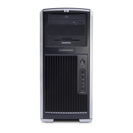
Front panel components The following image shows a typical HP xw8400 Workstation. Drive configurations can vary. Figure 1-2 Front panel components Table 1-2 Front panel components Item Symbol Optical drive 5.25-inch drive bay Diskette drive (optional) IEEE-1394a connector Microphone connector... -
Page 12: Rear Panel Components
Rear panel components Figure 1-3 Rear panel components Table 1-3 Rear panel components Item Symbol Power cord connector Built In Self Test (BIST) LED Keyboard connector Serial connector USB 2.0 ports IEEE-1394a connector Microphone connector Audio line-out connector MiniSAS 4–port connector (optional) The rear panel connectors are labeled with industry-standard icons and colors to assist you in connecting your peripheral devices. -
Page 13: Serial Number And Coa Label Location
Serial number and COA label location Each workstation has two unique serial number labels. Systems preinstalled with Microsoft® Windows® XP also have a certificate of authentication (COA) label (2). The serial number labels (1) are located on the side panel of the unit and on the rear panel. Keep the serial number available when contacting customer service for assistance. -
Page 14: Product Specifications
Product specifications The following table lists the physical dimensions. Table 1-4 Physical characteristics Weight (depending on configuration) Tower dimensions Rack mount dimensions (top cover and foot removed) Power supply and cooling This section describes power supply specifications. Table 1-5 Voltage specification Voltage Minimum 3.3 V... -
Page 15: Power Supply Specifications
Table 1-6 Current specification (continued) Current Minimum 12 VCPU1 12 V-M 12 V-B 12 V-D 12 V-G V12N 5 VSB WARNING! Do not exceed 135 W of a 5-V and 3.3-V power combination. Do not exceed 64 A (768 W) of a 12-V (CPU0/CPU1/M/B/D/E) power combination. Do not exceed 800 W of total continuous output power. -
Page 16: Power Consumption And Cooling
Table 1-7 Power supply specifications (continued) FEMP standby power compliant (<2 W in S5 - Power Off) BIST LED Surge tolerant full ranging power supply Power consumption and cooling The following table shows the primary power consumption for an example configuration: ●... -
Page 17: Resetting The Power Supply
The length of the cord must be between 6 feet (1.8 m) and 12 feet (3.6 m). If you have questions about the type of power cord to use, contact the HP authorized service provider. -
Page 18: Pci Card Slot Power Specification
75 W maximum from the auxiliary graphics power connector. NOTE If a graphics card requiring more than 75 W is installed, HP recommends not using slot 3, which is the PCI Express slot below the graphics slot. In addition to these slot power specifications, the overall power consumption of the system (including I/O cards, processors, memory, and drives) must not exceed the maximum ratings of the system power supply. -
Page 19: Energy Star
HP products purchased with the Energy Star configuration are compliant with U.S. Environmental Protection Agency (EPA) Computers Program. The EPA Energy Star configuration does not imply endorsement by the EPA. As an Energy Star partner, HP offers products with the Energy Star configuration to meet the Energy Star guidelines for energy efficiency. -
Page 20: Hyper-Threading Technology
Computer Setup (F10) during the boot process and select Advanced>Power-On Option>Hyper-Threading, and enable Hyper-Threading Technology. NOTE HP recommends using Hyper-Threading Technology with Windows XP systems. This technology is detected by the system and is turned on in the operating system after it is enabled in the system BIOS. -
Page 21: Installing Or Restoring The Operating System
Installing or restoring the operating system This chapter describes the installation and restoration of the operating system. ● Installing the Operating System and Software on page 14 ● Restoring the operating system on page 17 ● Protecting the software on page 18 ●... -
Page 22: Installing The Operating System And Software
After the boot process completes, you can view additional HP Linux documentation by opening your Internet browser (the browser is automatically set to use the local HP documentation page as its default). You can also access Linux Web links for Red Hat (Internet access required) by using your Internet browser. -
Page 23: Restoring The Linux Operating System
Restoring the Linux operating system To restore the Linux operating system, the HP Driver CD and Red Hat box set are required. Download the latest HP Driver CD to get any new enhancements. Linux does not support mixed drive types for a manufacturing preload. When restoring the operating system, mixed drive types can be handled with the restoring media. -
Page 24: Linux-Enabled Workstations
Red Hat box set. The Installer kit includes the HP CDs necessary to complete the installation of all versions of the Red Hat box set that have been verified to work on HP workstation hardware. -
Page 25: Restoring The Operating System
Restoring the operating system Restore the original Microsoft Windows XP Professional operating system and factory-installed software to a near-factory state by using the Restore Plus! CD and the operating system CD that came with your workstation. Carefully read and follow the instructions provided with the Restore Plus! CD. For information about restoring the Linux OS or software, see on page ENWW... -
Page 26: Protecting The Software
Protecting the software To protect software from loss or damage, keep a backup copy of all system software, applications, and related files stored on the hard drive. See the operating system or backup utility documentation for instructions on making backup copies of data files. Chapter 2 Installing or restoring the operating system ENWW... -
Page 27: Ordering Backup Software
All software that shipped with your workstation, including the Restore Plus! CD, can be ordered from HP as a single set, or you can order the various software packages separately. NOTE Before calling HP to order the software, be sure to have the serial number of your workstation available. See ENWW Serial number and COA label location on page 5 for details. - Page 28 Chapter 2 Installing or restoring the operating system ENWW...
-
Page 29: System Management
System management This section describes the various tools and utilities that allow for the system management of the workstation. ● Computer Setup (F10) Utility on page 22 ● Desktop management on page 32 ENWW... -
Page 30: Computer Setup (F10) Utility
Computer Setup (F10) Utility The Computer Setup (F10) Utility enables you to: ● Change factory default settings and set or change the system configuration, which might be necessary when you add or remove hardware. ● Determine if all of the devices installed on the workstation are recognized by the system and functioning properly. -
Page 31: Bios Rom
ACPI 1.0 and 2.0 and OnNow ● SMBIOS 2.5 ● PC98/99/00 and NetPC ● HP Preboot Execution Environment (PXE) boot ROM for the integrated LAN controller ● BIOS Boot Specification 1.01 ● Enhanced Disk Drive Specification 3.0 ● “El Torito” Bootable CD-ROM Format Specification 1.0 ●... -
Page 32: Computer Setup (F10) Utility Menu
Use the left and right arrow keys to select the appropriate heading. Use the up and down arrow keys to select the option you want, and press Enter. To apply and save changes, select File>Save Changes and Exit. ● If you have made changes that you do not want applied, select File>Ignore Changes and Exit. - Page 33 Table 3-1 Computer Setup (F10) Utility menu descriptions (continued) Heading Option Save Changes and Exit Storage Device Configuration Storage Options ENWW Description Saves changes to system configuration and exits the Computer Setup (F10) Utility. Lists all installed storage devices including hard disk, SATA 0, USB, CD-ROM, IDE Primary 0, and IDE/SATA.
- Page 34 Table 3-1 Computer Setup (F10) Utility menu descriptions (continued) Heading Option DPS Self-Test Boot Order Security Setup Password Chapter 3 System management Description Sets the SATA emulation mode with the following options: ● RAID/AHCI–Requires one of the two Intel SATA option ROMs to run. In this mode, the Option ROM manages the drives so they are not shown in Device Configuration.
- Page 35 Table 3-1 Computer Setup (F10) Utility menu descriptions (continued) Heading Option Power-On Password Password Options Smart Cover Device Security Network Service Boot System IDs ENWW Description NOTE If the setup password is set, you must enter Computer Setup (F10) Utility to change it, flash the ROM, and make changes to certain plug-and-play settings under Windows.
- Page 36 Table 3-1 Computer Setup (F10) Utility menu descriptions (continued) Heading Option OS Security Power OS Power Management Hardware Power Management Thermal Advanced Power-On Options Chapter 3 System management Description UUID (Universal Unique Identifier) Can only be updated if the current chassis serial number is invalid. (These ID numbers are normally set in the factory and are used to uniquely identify the system.) Keyboard Enables you to set the keyboard locale for System ID entry.
- Page 37 Table 3-1 Computer Setup (F10) Utility menu descriptions (continued) Heading Option BIOS Power- Processors Onboard Devices ENWW Description F9 Prompt (enable/disable) When enabled, displays F9=Boot Menu during POST. Displaying this feature prevents the text from being displayed, but pressing still forces the system to attempt booting from the network. F10 prompt (enable/disable) When enabled, displays F10=Setup during POST.
- Page 38 Table 3-1 Computer Setup (F10) Utility menu descriptions (continued) Heading Option Chipset/ Memory Device Options Chapter 3 System management Description Diskette Controller Enables you to set I/O, IRQ, and DMA channel for the device. PCI SERR# Generation (enable/disable) Disables PCI SERR# generation for ill-behaved PCI add-in cards (that can generate SERR# spuriously).
- Page 39 Table 3-1 Computer Setup (F10) Utility menu descriptions (continued) Heading Option Slot Options * Available on select models. ** These options should be used by advanced users only. ENWW Description Enables you to allow peer-to-peer memory reads between the PCI-X buses behind the PXH-V. Fast Delayed Transaction Timer Enables you to set Discard Transaction Timer to “short delay.”...
-
Page 40: Desktop Management
Desktop management HP Client Management Solutions (available for download from http://www.hp.com/go/easydeploy) provides standards-based solutions for managing and controlling workstations in a networked environment. This section summarizes the capabilities and features of desktop management key components: ● Initial configuration and deployment on page 32 ●... -
Page 41: Managing And Updating Software
Altiris Client Management solutions HP and Altiris have partnered to provide comprehensive, tightly integrated systems management solutions to reduce the cost of owning HP client PCs. HP Client Manager Software is the foundation for additional Altiris Client Management Solutions that address: ●... -
Page 42: System Software Manager
Subscriber’s Choice Subscriber’s Choice is a client-based service from HP. Based on your profile, HP supplies you with personalized product tips, feature articles, and driver and support alerts and notifications. Subscriber’s Choice Driver and Support Alerts/Notifications deliver e-mails notifying you that the information you subscribed to in your profile is available for review and retrieval. -
Page 43: Rom Flash
Remote ROM flash Remote ROM Flash enables you to safely upgrade the ROM on remote HP workstations directly from the centralized network management console. Performing this task remotely on multiple workstations and personal computers results in a consistent deployment of and greater control over HP PC ROM images over the network. -
Page 44: Replicating The Setup
Insert a ROMPaq diskette into the diskette drive, or if permitted on this workstation, insert a ROMPaq CD into the CD drive. USB media such as an HP DriveKey can also be used. Power on the workstation. -
Page 45: Copying To A Single Workstation
For example, do not copy the setup configuration from an HP xw6200 Workstation to an HP xw8400 Workstation. Select a setup configuration to copy. Power off the workstation. In Windows, click Start>Shut Down>Shut Down. -
Page 46: Dual-State Power Button
Worldwide web site HP engineers rigorously test and debug software developed by HP and third-party suppliers, and develop operating system specific support software, to ensure performance, compatibility, and reliability for HP workstations. -
Page 47: Building Blocks And Partners
HP has made the task of locating, accessing, evaluating, and installing the latest support software easier. You can download the software from http://www.hp.com/support. The Web site contains the latest device drivers, utilities, and flashable ROM images needed to run the latest Microsoft Windows operating system on the HP workstation. -
Page 48: Password Security
Table 3-3 Security features overview Feature Removable Media Boot Control Prevents booting from the removable media Serial, Parallel, USB, or Infrared Interface Control Power-On Password Setup Password Network Server Mode Ownership Tag Kensington Cable Lock Provision Padlock Loop Access Panel Key Lock (Standard) Universal Chassis Clamp Lock (Optional) -
Page 49: Establishing A Setup Password In The Computer Setup (F10) Utility
NOTE System Software Manager and HP Client Manager Software allow remote management of setup passwords and other BIOS settings in a networked environment. For more information, see http://www.hp.com/go/easydeploy. Establishing a setup password in the Computer Setup (F10) Utility Establishing a setup password through the Computer Setup (F10) Utility prevents reconfiguration of the workstation (through use of the Computer Setup (F10) Utility) until the password is entered. -
Page 50: Entering A Power-On Password
Select Security>Power-On Password, and follow the on-screen instructions. Before exiting, select File>Save Changes and, Exit. Entering a power-on password To enter a power-on password: Power on or restart the workstation. In Windows, click Start>Shut Down>Restart the Computer. When the key icon appears on the monitor, enter the current password, and press Enter. NOTE Type carefully. -
Page 51: Changing A Power-On Or Setup Password
National keyboard delimiter characters on page 44 key again to access the utility. National keyboard delimiter characters on page 44 key until you enter the Computer for information Enter to bypass the title screen, if for information about the Desktop management... -
Page 52: National Keyboard Delimiter Characters
National keyboard delimiter characters Each keyboard is designed to meet country-specific requirements. The syntax and keys that you use for changing or deleting your password depend on the keyboard that came with your workstation. Table 3-4 National keyboard delimiter characters Arabic Belgian BHCSY*... -
Page 53: Setting The Hood Sensor Protection Level
Drive Protection System The Drive Protection System (DPS) is a diagnostic tool built into the hard drives installed in select HP workstations. DPS is designed to help diagnose problems that might result in unwarranted hard drive replacement. -
Page 54: Ecc Fault Prediction And Pre-Failure Warranty
The processor thermal sensor is a hardware and software feature that tracks the internal temperature of the workstation. When combined with HP Client Manager Software, this features notifies the network administrator when the normal range is exceeded. In this case, the processor clock automatically begins to throttle. -
Page 55: Removal And Replacement Procedures
Removal and replacement procedures This chapter describes removal and replacement procedures of most internal components. ● Service considerations on page 48 ● Customer Self Repair on page 52 ● Pre-disassembly procedures on page 53 ● System board components on page 54 ●... -
Page 56: Service Considerations
Service considerations The following sections discuss service considerations that should be reviewed and practiced before removing and replacing any system components. WARNING! or lifting point. Lifting the workstation from the front bezel or lifting it incorrectly can cause the unit to fall and harm the user and damage the workstation. -
Page 57: Preventing Electrostatic Damage To Equipment
Preventing electrostatic damage to equipment Many electronic components are sensitive to ESD. Circuitry design and structure determine the degree of sensitivity. The following packaging and grounding precautions are necessary to prevent damage to electric components and accessories. ● Transport products in static-safe containers, such as tubes, bags, or boxes, to avoid hand contact. ●... -
Page 58: Recommended Materials And Equipment
If an incorrect screw is used during the reassembly process, it can damage the unit. HP strongly recommends that all screws removed during disassembly be kept with the removed part and then returned to their proper locations. -
Page 59: Cables And Connectors
Cables and connectors Cables must be handled with care to avoid damage. Apply only the tension required to seat or unseat the cables during insertion or removal from the connector. Handle cables by the connector or pull strap whenever possible. In all cases, avoid bending or twisting the cables, and be sure that the cables are routed in such a way that they cannot be caught or snagged by parts being removed or replaced. -
Page 60: Customer Self Repair
Customer Self Repair Customer Self Repair (CSR) enables you to obtain replacement parts and install them yourself on your workstation. The following table indicates which workstation components are customer-serviceable. http://www.hp.com/go/selfrepair/ Table 4-3 Customer Self Repair components Item Description SYSTEM BOARD... -
Page 61: Pre-Disassembly Procedures
Pre-disassembly procedures Perform the following steps before servicing the workstation: Remove or disengage any security devices that prohibit opening the workstation. Close any open software applications. Remove any diskettes or CDs from the workstation. Exit the operating system. Shut down the workstation and any peripheral devices that are connected to it. Disconnect the power cord from the electrical outlet and then from the workstation. -
Page 62: System Board Components
System board components The following image shows the system board connectors and sockets on the HP xw8400 Workstation. Figure 4-1 System board identification Table 4-4 System board components Item Description Memory Fan PS/2 Keyboard/ Mouse Parallel Serial Network/USB Internal USB... -
Page 63: System Board Architecture
* The Primary IDE connector is generally used for hard drives. ** The PCI Express x8 is a PCI Express x8 connector that has x4 bandwidth. System board architecture The following image shows the HP xw8400 Workstation block diagram. Figure 4-2 System board block diagram... -
Page 64: Removing And Replacing Components
2. If the content you desire is not referenced in this chapter, see xw8400_manuals 3. See the manufacturer’s web site for instructions for a third party (non-HP) component. Disassembly order Use the following table to determine the sequence in which to remove the major components. -
Page 65: Removing The Security Lock (Optional)
Removing the security lock (optional) If a security padlock is installed, remove it before servicing the unit. To remove the padlock, unlock it and slide it out of the padlock loop as shown in the following image. ENWW Power button and front speaker (Power button assembly and system... -
Page 66: Removing The Cable Lock (Optional)
Figure 4-3 Removing the security lock Removing the cable lock (optional) If a cable lock is installed, remove it before servicing the unit. To remove the cable lock, unlock it and pull it out of the cable lock slot as shown in the following image. Figure 4-4 Removing the cable lock Access panel... -
Page 67: Front Bezel
WARNING! powered off and that the power cord is disconnected from the electrical outlet. Disconnect power from the system. If a lock is present, unlock the access panel. The keys are on the rear panel components on page Pull up on the handle and lift off the cover. Figure 4-5 Opening the access panel To replace the access panel, slide the cover back on until it snaps into place. -
Page 68: Bezel Blanks
Figure 4-6 Opening the front bezel Bezel blanks To remove the bezel blanks: Disconnect power from the system ( front bezel (Front bezel on page Remove the bezel blanks by squeezing in on the tabs (1) and pushing the bezel blanks out (2). Figure 4-7 Removing the bezel blanks Chapter 4 Removal and replacement procedures... -
Page 69: Hood Sensor (Smart Cover Sensor)
Hood sensor (Smart Cover Sensor) To remove the hood sensor: Disconnect power from the system ( access panel (Access panel on page facing up. Disconnect the white 1 x 3 hood sensor connector from the inline connector attached to the front panel harness. -
Page 70: Power Button Assembly And System Speaker
Pull the bracket away from the front panel I/O device assembly. Figure 4-9 Removing the front panel I/O device assembly Slide the front panel cables through the chassis and out the front of the unit. To replace the front panel I/O device assembly, reverse the previous steps. Power button assembly and system speaker The power button and the system speaker are part of the same assembly. -
Page 71: Power Supply
Slide the speaker away from the three flanges and remove it from the chassis. Figure 4-10 Removing the speaker Power supply Disconnect power from the system ( access panel (Access panel on page facing up. Disconnect the power supply from the system board. CAUTION PCI Express x16 graphics card and which power cable was disconnected from the system board. -
Page 72: System/Memory Fan Assembly
Figure 4-11 Removing the power supply To install the power supply, reverse the previous steps. System/memory fan assembly The system fan and memory fan are connected and treated as a unit. To remove the system/memory fan assembly: Disconnect power from the system ( access panel (Access panel on page facing up. -
Page 73: Memory
No support for mirroring ● No spare DIMM support ● Standard FBD, ECC (72-bit ECC) Memory module requirements ● Use only PC2-5300F, FBDs. Certified and warranted HP memory is recommended. ● Match DIMM pairs by size and type. ENWW Removing and replacing components... -
Page 74: Removing Memory Module
Removing memory module Disconnect power from the system ( access panel (Access panel on page facing up. CAUTION installation, power off the workstation and unplug the power cord from the AC power outlet. Wait until the LED on the back of the power supply turns off before removing memory. If you do not unplug the power cord while installing memory, your memory modules might be damaged and the system will not recognize the memory changes. -
Page 75: Installing Memory Module
DIMM. Installing memory module CAUTION HP only ships DIMMs that are electrically and thermally compatible with this product. Because third-party DIMMs might not be electrically or thermally compatible, they are not supported by HP. You must load memory modules in valid configurations: ●... -
Page 76: Installing A Dimm
● Load the memory module pairs in order of size, from smallest to largest. Figure 4-15 Identifying memory slots The BIOS generates warnings/errors on invalid memory configurations. ● If there is no way to obtain a valid memory configuration by disabling some of the plugged-in memory, the BIOS will halt with a diagnostics 2006 code for memory error (five beeps and blinks). -
Page 77: Pci Slots
Gently push out on the socket levers. Lower the DIMM straight down, and be sure the socket levers secure the module into place. Lower the memory fan until it snaps into place. NOTE Ensure that all cables are clear of the fan housing when lowering the memory fan. PCI slots Figure 4-17 Identifying PCI slots... -
Page 78: Removing The Pci Retainer
Removing the PCI retainer Disconnect power from the system ( access panel (Access panel on page facing up. For short or tall cards, lift the PCI retainer arm (1) with one hand, press in on the sides (2) of the retainer, and rotate it (3) out of the chassis. -
Page 79: Pci Retention Clamp
For short or tall PCI cards, attach the hooks of the PCI retainer (1) under the slots on the rear of the chassis, and then rotate the retainer down until the retainer arm (2) supports the card. Figure 4-19 Installing the short or tall card PCI retainer PCI retention clamp Disconnect power from the system ( access panel... -
Page 80: Pci Express
PCI Express x8 slot. NOTE Slot 3: The HP xw8400 Workstation contains one PCI Express x8 slot that supports x4 bandwidth. If a PCI Express x8 card is plugged into the PCI Express x8 slot, the card runs at x4 bandwidth. -
Page 81: Pci Or Pci Express Installation
Lift the PCI card out of the chassis (2). If removing a PCI Express high-end graphics card, remove the auxiliary power supply cable (not illustrated) if required, and move the lever to release the card and lift it out of the chassis (3). Store the card in an anti-static bag. Close the PCI retention clamp. -
Page 82: Front Fan Removal (Optional)
Figure 4-22 Installing the PCI or PCI-E card Front fan removal (Optional) To remove the front fan: Disconnect power from the system ( access panel (Access panel on page facing up. Disconnect the fan wire from the connector on the system board. Release the two card guide latches. - Page 83 Remove the fan from the card guide by applying outward pressure on the card guide while lifting the fan away. Figure 4-24 Removing the fan from the card guide To install the front fan: Place the fan in the card guide with the fan label facing into the card guide, and the fan protector screen facing outward.
-
Page 84: Battery
Battery CAUTION Before removing the battery, be sure your CMOS settings are backed up because all CMOS settings are lost when the battery is removed. To back up the CMOS settings, use Computer Setup and run the Save to Diskette option from the File menu. Disconnect power from the system ( access panel (Access panel on page... -
Page 85: Optical Drive
Figure 4-27 Identifying correct power connections Table 4-7 Power connector descriptions Connector 24–pin Power Connector 4–pin Memory Connector 8–pin CPU0 Connector P4–P8 HDD/Optical Connector Diskette Connector P10–P14 HDD Connector PCI-E Connector Optical drive Your workstation might have a SATA or an IDE optical drive. To remove the optical drive. Disconnect power from the system ( panel (Access panel on page... - Page 86 Disconnect the audio (1), data (2), and power (3) cables from the drive. The connector colors might be different than illustrated. NOTE The audio cable is only required for Linux-based systems. Figure 4-28 Disconnecting the IDE (left) or SATA (right) cable from the optical drive Lift the green drivelock release lever, and gently slide the drive out of the chassis.
-
Page 87: Replacing The Sata Optical Drive Data Cable
To replace an optical drive: Lift the green drivelock release lever while sliding the optical drive into the bay. When the optical drive is partially inserted, release the drivelock release lever, and slide the drive completely into the bay until the drive is secured. CAUTION the drive when moving the workstation. -
Page 88: Diskette Drive (Optional)
Figure 4-31 Connecting the SATA optical drive cable to the system board Diskette drive (optional) To remove a diskette drive: Disconnect power from the system ( panel (Access panel on page Disconnect the cables from the back of the diskette drive. Figure 4-32 Disconnecting cables from the diskette drive Chapter 4 Removal and replacement procedures... - Page 89 While lifting the green drivelock release tab, slide the drive forward out of the chassis. Figure 4-33 Removing the diskette drive from the chassis Remove the diskette drive from its bracket by removing the two M3 screws in the rear-most holes and pulling the diskette drive from the bracket.
-
Page 90: Hard Drive
Route the diskette drive data cable between the system board and the hard drive cage. Your cable might look different than the one shown. CAUTION be necessary to push the cable down so that it catches on the system board. This routing method is important because it avoids interference with the CPU heatsink fans and blocking airflow. -
Page 91: Installing A Hard Drive
Push in on the green drivelock release tabs, and pull the hard drive out of the chassis. Figure 4-36 Removing the hard drive Installing a hard drive Select a drive bay in which to install the drive. If installing more than one hard drive, use the hard drive order shown in the following image. - Page 92 Attach the rails to the hard drive. Align the pins on the rails with the hard drive holes, and snap the rails into place. Figure 4-38 Attaching rails to the hard drive Push the drive into the selected bay until it snaps into place. Attach a data cable from a SATA connector on the system board to the hard drive, and attach a power cable to the drive.
-
Page 93: Installing A Hard Drive In The Fifth Hard Drive Bay
For a SAS hard drive, attach a SAS/SATA adapter to the connector on the hard drive. Attach a data cable from a SAS connector on the system board to the hard drive, and attach a power cable to the drive. Figure 4-40 Installing the SAS/SATA adapter (left) and cable (right) Installing a hard drive In the fifth hard drive bay... -
Page 94: Processor Heatsink
Attach a data cable from a SATA connector on the system board to the hard drive, and attach the fifth drive power cable to the drive. Figure 4-42 Attaching the data cable for the SATA hard drive in the fifth hard drive bay Processor heatsink Removing the CPU heatsink NOTE... - Page 95 Remove the four processor screws slowly, being sure to loosen all the screws evenly. Loosen one pair of diagonally opposite screws (1) until the screw shanks disengage from the system board, and then loosen the remaining pair (2). Do not fully loosen one screw, then move on to the next. Loosen all of the screws a little at a time, so that the processor remains level.
-
Page 96: Replacing The Cpu Heatsink
Replacing the CPU heatsink Disconnect power from the system ( panel (Access panel on page on page 86). Use alcohol and a soft cloth to clean all of the thermal interface material residue from the CPU heatsink and processor. CAUTION Place the CPU heatsink on top of the processor, and align the four mounting screws with the holes (1) in the system board. -
Page 97: Processor
Insert and tighten the four CPU heatsink screws. First, tighten all of the screws partially so that the CPU heatsink remains level. Next, fully tighten one pair of diagonally opposite screws (1), and then fully tighten the remaining pair (2). Tighten firmly to a torque setting of 6 in-lb. Figure 4-46 Identifying proper screw removal order Connect the CPU heatsink fan connector to the system board (2) as shown in Figure 1–45. - Page 98 Raise the processor socket handle (1) fully (the full swing angle of the lever is approximately 105 degrees). Lift the processor socket cover (2). Figure 4-47 Raising the processor socket handle Lift the processor straight out of the socket. Figure 4-48 Lifting the processor from the socket CAUTION To avoid bending the socket pins, keep the processor perfectly flat when removing...
-
Page 99: Replacing The Processor
Replacing the processor Disconnect power from the system ( panel (Access panel on page and the processor Raise the processor socket handle fully (the full swing angle of the lever is approximately 105 degrees). CAUTION processor in the socket to avoid bending pins. Align the notches in the processor base with the tabs on the socket. -
Page 100: System Board
System board Removing the system board Disconnect power from the system ( access panel (Access panel on page facing up. Remove all expansion boards, graphics cards on page 72), and the CPU heatsink remove the system/memory fan assembly Disconnect all cables from the system board. CAUTION PCI Express x16 graphics card and which power cable was disconnected from the system board. -
Page 101: Replacing The System Board
Replacing the System Board: Insert the system board straight down, and be sure that all system board standoffs engage with the keyholes in the chassis. NOTE Be sure the system board connectors engage correctly with the rear I/O panel. Push back on the board while maintaining downward pressure on the board, so all standoffs remain engaged. - Page 102 Chapter 4 Removal and replacement procedures ENWW...
-
Page 103: System Diagnostics And Troubleshooting
E-Support on page 96 ● Troubleshooting checklist on page 97 ● LED color definitions on page 98 ● HP Insight Diagnostics Offline Edition on page 99 ● Diagnostic error codes on page 104 ● Troubleshooting scenarios and solutions on page 106 ●... -
Page 104: E-Support
To open HSC from your desktop, click Start>Help and Support. HSC contains four sections: ● HP Product Information (requires Internet access)—Links to the HP Technical Support website for your product. You can access all related documentation, downloads and updates, tools, and more. ●... -
Page 105: Troubleshooting Checklist
Troubleshooting checklist Before running any of the diagnostic utilities, use the following checklist to find possible solutions for workstation or software problems. ● Are the workstation and monitor connected to a working electrical outlet? ● Is the workstation powered on? ●... -
Page 106: Led Color Definitions
LED color definitions The front panel LED indicates system status as described in Table 1. Table 5-1 Front panel LED color definitions LED State Solid Blinking Solid or blinking None Chapter 5 System diagnostics and troubleshooting LED Color Green System is on. Green System is in Standby mode. -
Page 107: Hp Insight Diagnostics Offline Edition
HP Insight Diagnostics Offline Edition The HP Insight Diagnostics utility enables you to perform testing and to view critical computer hardware and software configuration information from various sources. This utility enables you to: ● Run diagnostics. ● View the hardware configuration of the system. -
Page 108: Download The Iso Image
Download the ISO image Browse to http://www.hp.com. Click Software & Driver Downloads. Enter your product number (for example, xw8400) in the text box, and press the Select your operating system. Click the Diagnostic link. Locate HP Insight Diagnostics Offline on the display, and click Download. -
Page 109: Test Tab
To view all test failure information, select Error Log. To view the status of all testing that has been performed, click the Log tab. ENWW HP Insight Diagnostics Offline Edition... -
Page 110: Status Tab
Clicking the Clear Error Log button clears the contents of the Error Log. Help tab The Help tab has three views: ● HP Insight Diagnostics—Provides introductory and detailed information about Insight Field Diagnostics. ● Error Codes—Provides error code listings. It includes device tested, message, and recommended repair information. - Page 111 Reload—Located in the upper-right corner of the display, this selection reloads all hardware components. ● About—Provides revision details of Insight Diagnostics. ● Exit—Located in the lower-left corner of the display, this selection provides the option to exit diagnostics. ENWW HP Insight Diagnostics Offline Edition...
-
Page 112: Diagnostic Error Codes
Diagnostic error codes This sections provides an overview of the diagnostic lights and error codes that are related to your workstation. Diagnostic light codes NOTE The beeps are heard through the onboard piezo speaker and not the chassis speaker. The blinking LEDs and beeps repeat for five cycles. After that, only the blinking LEDs repeat. Table 5-2 Diagnostic LED codes Power LED and Sound Activity... - Page 113 ● Reseat memory modules. ● Replace memory modules one at a time to find the faulty module. ● Replace third-party modules with HP memory. ● Replace system board. Pre-video graphics card error. For systems with integrated graphics, replace system board.
-
Page 114: Troubleshooting Scenarios And Solutions
Troubleshooting scenarios and solutions This section presents an extensive overview of various troubleshooting scenarios and includes possible solutions for each. Solving minor problems Table 5-3 Minor problems Problem Workstation appears locked up and will not turn off when the power button is pressed. Workstation seems to be locked up. -
Page 115: Solving Power Supply Problems
Table 5-3 Minor problems (continued) Problem Solving power supply problems Testing power supply Before replacing the power supply, use the BIST feature to determine if the power supply still works. To test the power supply: Disconnect all internal power supply cables. Plug in AC power. - Page 116 Figure 5-1 Power supply Table 5-4 Power supply problems Problem Power supply shuts down intermittently. Chapter 5 System diagnostics and troubleshooting Cause Power supply fault. Replace the power supply. Solution ENWW...
-
Page 117: Solving Diskette Problems
Table 5-4 Power supply problems (continued) Problem Workstation powered off automatically and the Power LED flashes red two times, once every second, followed by a two-second pause. Power LED flashes red, once every two seconds. Solving diskette problems Table 5-5 Diskette problems Problem Diskette drive light stays on. - Page 118 Table 5-5 Diskette problems (continued) Problem Diskette drive cannot write to a diskette. Cannot format diskette. A problem has occurred with a disk transaction. Diskette drive cannot read a diskette. “Invalid system disk” message is displayed. Cannot Boot to Diskette. Chapter 5 System diagnostics and troubleshooting Cause Diskette is not formatted.
-
Page 119: Solving Hard Drive Problems
Solving hard drive problems Table 5-6 Hard drive problems Problem Hard drive error occurs. Disk transaction problem. Drive not found (identified). Non-system disk/NTLDR missing message. Non-system disk/NTLDR missing message. Workstation will not start. ENWW Cause Hard disk has bad sectors or Use a utility to locate and block usage of bad sectors. -
Page 120: Solving Display Problems
Solving display problems Table 5-7 Display problems Problem Blank screen (no video). The display works properly during the POST but goes blank when the OS starts. Power LED flashes Red six times, once every second, followed by a two second pause, and the workstation beeps six times. -
Page 121: Solving Audio Problems
Table 5-7 Display problems (continued) Problem Blurry video or requested resolution cannot be set. The picture is broken up, rolls, jitters, or flashes. Vibrating or rattling noise coming from inside a CRT monitor when powered on. Clicking noise coming from inside a CRT monitor. - Page 122 Table 5-8 Audio problems (continued) Problem Noise or no sound comes out of the speakers or headphones. NOTE If you set digital as the Output Mode, the internal speaker and external analog speakers will no longer output audio until you switch back to an auto-sense or analog mode. If you set analog as the Output Mode, external digital speakers will not function until you change the output mode back to an auto-sense or digital mode.
-
Page 123: Solving Printer Problems
Solving printer problems Table 5-9 Printer problems Problem Printer does not print. Printer does not turn on. Printer prints garbled information. Printer is offline. Solving keyboard and mouse problems Table 5-10 Keyboard and mouse problems Problem Keyboard commands and typing are not recognized by the workstation. -
Page 124: Solving Front Panel Component Problems
Table 5-10 Keyboard and mouse problems (continued) Problem Mouse does not respond to movement or is too slow. Mouse will only move vertically or horizontally, or movement is jerky. Solving front panel component problems If you are experiencing problems with one of the front panel ports, you might be able to try your device in the corresponding port on the back side of the computer. -
Page 125: Solving Hardware Installation Problems
The port is not there because it You can buy an IEEE 1394 PCI adapter card. Contact an was not purchased with the HP seller. system. Cause Device is not seated or Be sure that the device is properly and securely connected connected properly. -
Page 126: Solving Network Problems
Solution Reseat DIMMs. Replace DIMMs one at a time to isolate the faulty module. Replace third-party memory with HP memory. Replace the system board. Reseat the graphics card. Replace the graphics card. Replace the system board. -
Page 127: Solving Memory Problems
System setup utility reports unprogrammed EEPROM. Solving memory problems CAUTION For those systems that support ECC memory, HP does not support mixing ECC and non-ECC memory. Otherwise, the system will not boot the operating system. Table 5-14 Memory problems Problem... -
Page 128: Solving Processor Problems
Reseat DIMMs. or is bad. Replace DIMMs one at a time to isolate the faulty module. Replace third-party memory with HP memory. Replace the system board. Cause Processor is hot. Be sure the airflow to the workstation is not blocked. -
Page 129: Solving Internet Access Problems
Table 5-16 CD-ROM and DVD problems (continued) Problem Movie will not play in the DVD drive. Movie might be regionalized Cannot eject compact disc (tray- load unit). CD-ROM, CD-RW, DVD-ROM, or DVD-R/RW drive cannot read a disc or takes too long to start. Recording audio CDs is difficult or impossible. - Page 130 Table 5-17 Internet access problems (continued) Problem Cannot automatically launch Internet programs. Internet takes too long to download websites. Chapter 5 System diagnostics and troubleshooting Cause is good, the “PC” LED light on the front of the cable/DSL modem will be on.) IP address is not configured Contact the ISP for the correct IP address.
-
Page 131: Post Error Messages
Remove expansion boards. Replace the system board. Move the suspected card to a different slot to see if the error resolves. Contact HP for assistance if necessary. Run Computer Setup (F10 Setup). Set the date and time under Control Panel or in F10 Setup, depending on the operating system. - Page 132 If the problem persists, be sure memory modules (if any) are installed correctly. If third-party memory has been added, test using HP memory only. Verify proper memory module type. Run Computer Setup (F10 Setup) or Windows utilities.
- Page 133 Table 5-18 POST error messages (continued) Screen Message 214–DIMM Configuration Warning. 301–Keyboard Error. 303–Keyboard Controller Error. 304–Keyboard or System Unit Error. 401–Parallel Port 1 Address Assignment Conflict. 404–Parallel Port Address Conflict Detected. 410–Audio Interrupt Conflict. 411–Network Interface Card Interrupt Conflict. 501–Display Adapter Failure.
- Page 134 Table 5-18 POST error messages (continued) Screen Message 513–Memory fan not detected. Memory fan is not connected or it 601–Diskette Controller Error. 605–Diskette Drive Type Error. 610–External Storage Device Failure. 611–Primary Diskette Port Address Assignment Conflict. 912–Computer Cover Has Been Removed Since Last System Start Up.
- Page 135 Run the Drive Protection System test if applicable. Apply firmware patch if applicable (see http://www.hp.com/support). Back up contents and replace hard drive. Be sure that power and drive cables are connected to the drive and to the system board.
- Page 136 Combined IDE Controller in Setup. Internal temperature exceeds specification. Missing or Invalid Processor Microcode Update. Contact HP for a new Microcode Update to support the new Processor Stepping. The system board does not support the processor. Electronic serial number has become corrupted.
- Page 137 Appendix A — SAS devices ENWW...
-
Page 138: Supported Sas Raid Configurations
Supported SAS RAID configurations The following RAID configurations are supported on the HP xw8400 Workstation. NOTE This section does not apply to configuring RAID in the Linux environment. For RAID in the Linux environment, configure SW RAID configurations as provided by Red Hat Enterprise Linux. -
Page 139: Sas Raid 0 Configuration
SAS RAID 0 configuration Follow the steps below to configure an Integrated Striped (IS) volume with the BIOS-based configuration utility. The configuration procedure assumes that the system already has the required disk and disk controllers. On the Main menu screen of the BIOS-based configuration utility, use the arrow keys to select an adapter. -
Page 140: Sas Raid 1 Configuration
SAS RAID 1 configuration Follow the steps below to configure an Integrated Mirroring (IM) volume with the BIOS-based configuration utility. The configuration procedure assumes that the system already has the required disk and disk controllers. On the Main menu screen of the BIOS-based configuration utility, use the arrow keys to select an adapter. - Page 141 (Optional) Use the arrow keys to select a hot spare disk for the IM volume. Select Yes as the value for the Hot Spare column. When you have selected all disks for the IM volume, press exit this menu. (If you do not want to create the IM volume, select Discard changes, then exit this menu.
-
Page 142: Sas Raid 1E Configuration
SAS RAID 1E configuration Follow the steps below to configure an Integrated Mirroring Extended (IME) volume with the BIOS-based configuration utility. The configuration procedure assumes that the system already has the required disk and disk controllers. On the Main menu screen of the BIOS-based configuration utility, use the arrow keys to select an adapter. - Page 143 (Optional) Use the arrow keys to select a hot spare disk for the IME volume. Select Yes as the value for the Hot Spare column. When you have selected all disks for the IME volume, press exit this menu. (If you do not want to create the IME volume, select Discard changes, then exit this menu.
- Page 144 Appendix A Appendix A — SAS devices ENWW...
-
Page 145: Appendix B Appendix B -Sata Devices
Appendix B —SATA devices This appendix describes how to use the Intel® Matrix Storage Manager option ROM Configuration Utility to set up and manage SATA RAID volumes. NOTE If only a single HDD is attached, the Intel Matrix Storage Manager option ROM will not execute, and all associated messages will not be displayed. -
Page 146: Attaching Sata Hdds
Attaching SATA HDDs Attach the required number of SATA HDDs for the desired RAID level. ● RAID 0: two to six HDDs ● RAID 1: two HDDs ● RAID 5: three to six HDDs ● RAID 10: four to six HDDs Appendix B Appendix B —SATA devices ENWW... -
Page 147: Configuring System Bios
Configuring system BIOS Configure the system BIOS to enable embedded SATA RAID functionality. Press to enter the system BIOS setup. Use the arrow keys to highlight the desired language, then press Enter. Use ←, →, ←, and → to highlight Storage>Storage Options, then press Enter. Use the up or down arrow key to highlight SATA Emulation. -
Page 148: Creating Raid Volumes
Creating RAID volumes Use the Intel Matrix Storage Manager option ROM Configuration Utility to create RAID volumes Press Ctrl+I when prompted to enter the Intel Matrix Storage Manager option ROM Configuration Utility. If required, refer to to create the desired RAID volume. Use the up or down arrow key to highlight 1. -
Page 149: Deleting Raid Volumes
Deleting RAID volumes Use the Intel Matrix Storage Manager option ROM Configuration Utility to delete RAID volumes. Use the up or down arrow key to highlight 2. Delete RAID Volume, and press Enter. Use the up or down arrow key to highlight the RAID volume to be deleted, and press Del. When prompted, press Choose one of the following steps: ●... - Page 150 Appendix B Appendix B —SATA devices ENWW...
-
Page 151: Appendix C Appendix C - Ultra Ata Devices
Appendix C — Ultra ATA devices ENWW... -
Page 152: Ultra Ata Jumpers
NOTE This system supports a mixed configuration of UATA/IDE optical drives, and SAS and SATA hard drives. While HP supports the presence of SCSI and IDE hard drives, it does not ship any configurations using those drives. Ultra ATA drives are configured with jumper settings. Factory-installed drives ship with the jumpers preset to the cable-select mode;... -
Page 153: Ultra Ata Cables
Ultra ATA cables When installing a second device on either the primary or secondary controller, you must use an industry standard 80-conductor Ultra ATA cable for optimal performance. These cables have a maximum length of 18 inches and a maximum distance of six inches between the two devices for a two-drive cable. Drives operating at speeds faster than those of the Ultra ATA-33 devices require industry-standard 40- pin, 80-conductor cables to maintain the highest data transfer rates possible with the improved technology. -
Page 154: Drive Installation Guidelines
Drive installation guidelines Most workstation system boards have two ATA (IDE) controller channels with a dedicated connector for each controller. One controller is designated as the primary and the other as the secondary controller. Each of the two controllers can have up to two devices attached to it. Each workstation system might therefore have a maximum of four ATA/ATAPI drives. -
Page 155: Attach Sequence Worksheet
Primary Controller* Installing drive order *If there are three or more devices, two or more of which are hard drives, two hard drives should be attached to the primary controller first before following the general attach sequence rule. The attach sequence rule can also be stated in table format: Table C-2 General attach sequence rule Sequence... -
Page 156: Example 1: Three Device Installation Sample
Table C-3 Attach sequence worksheet (continued) Device name Two examples of how to use the worksheet are: ● Three device installation ● Four device installation Example 1: Three device installation sample A system has three devices: Ultra ATA-100 hard drive, CD-ROM drive, and a DVD drive. Using the Device Class Table, the devices can be identified as: ●... -
Page 157: Example 2: Four Device Installation Sample
Example 2: Four device installation sample A system has four devices: Ultra ATA-100 hard drive, Ultra ATA-100 hard drive, DVD-CDR/W drive, and a ZIP-250 drive. ● Ultra ATA-100 hard drive = Class 1 ● Ultra ATA-100 hard drive = Class 1 ●... -
Page 158: Smart
SMART The Self Monitoring Analysis and Recording Technology (SMART) ATA drives for HP workstations have built-in drive failure prediction that warns the user or network administrator of an impending failure or crash of the hard drive. The SMART drive tracks fault prediction and failure indication parameters, such as reallocated sector count, spin retry count, and calibration retry count. -
Page 159: Jumpers
Jumpers The following specification is the standard drive configuration. CD-ROM or DVD-ROM drive CD-ROM or DVD-ROM drive jumpers ENWW Jumpers... - Page 160 Appendix C Appendix C — Ultra ATA devices ENWW...
-
Page 161: Appendix D Appendix D - Connector Pins
Appendix D — Connector pins ENWW... -
Page 162: Connector Pin Descriptions
Connector pin descriptions Ethernet connector Parallel connector Signal Strobe Data Bit 0 Data Bit 1 Data Bit 2 Data Bit 3 Data Bit 4 Serial connector Appendix D Appendix D — Connector pins Signal Data Bit 5 Select Data Bit 6 Auto Linefeed Data Bit 7 Error... - Page 163 USB connector IEEE 1394 connector Microphone connector (1/8 inch) Headphone connector (1/8 inch) Line-in audio connector (1/8 inch) Line-out audio connector (1/8 inch) ENWW Signal +5 VDC - Data + Data Signal power tpb- tpb+ tpa- tpa+ Signal 1 (Tip) Audio 2 (Ring) Power...
- Page 164 Line-out audio connector (1/8 inch) SATA connector Signal Data Cable Ground S-2* S-3* Ground S-5** S-6** Ground * S2 and S3 differential signal pair **S5 and S6 differential signal pair SAS connector Segment Primary signal segment Appendix D Appendix D — Connector pins 3 (Shield) Signal Power Cable...
- Page 165 SAS connector Segment Secondary signal segment Power segment ENWW Backplane receptacle Plug and cable SIGNAL GROUND SIGNAL GROUND SIGNAL GROUND precharge GROUND GROUND GROUND precharge GROUND READY LED GROUND precharge receptacles Connector pin descriptions...
- Page 166 VGA cconnector Signal Red Analog Green Analog Blue Analog Monitor ID DVI connector Signal T.M.D.S DATA 2- T.M.D.S DATA 2+ T.M.D.S DATA 2/4 SHIELD T.M.D.S DATA 4- T.M.D.S DATA 4+ 2 DDC CLOCK DDC DATA ANALOG VERT. SYNC T.M.D.S DATA 1- T.M.D.S DATA 1+ T.M.D.S DATA 1/3 SHIELD T.M.D.S DATA 3-...
- Page 167 ATA/ATAPI (IDE) standard drive cable connector Signal Reset DD10 DD11 24-Pin Main power connector +3.3 V +3.3 V +5 V +5 V ENWW Signal DMAK DD14 INTRQ DD15 IOCS16 (Key) PDIAG (cable detect) DMARQ DIOW CS1FX CS3FX DIOR DASP IORDY CSEL -12 V +5 Vaux...
- Page 168 CAUTION Be sure you can differentiate between which power cable connects to the PCI Express x16 graphics card and which power cable connects to the system board. These two cables look very similar. The PCI Express power cable has a black connector, and the system board power cable has a white connector.
- Page 169 6-Pin power (auxiliary PCI Express) Keyboard connector Mouse connector ENWW Color Signal BLK w/YEL stripe +12V-C BLK w/YEL stripe +12V-C BLK w/YEL stripe +12V-C Signal Data Unused Ground +5 VDC Clock Unused Signal Data Unused Ground +5 VDC Clock Unused Connector pin descriptions...
- Page 170 Appendix D Appendix D — Connector pins ENWW...
- Page 171 Appendix E — System board designators This appendix lists the system board designators for this system. Designator MH02-03, MH06-09, MH14-15 BBLK_WP PSWD SLOT1 PCI SLOT5 PCI-X 133 SLOT6 PCI-X 100 SLOT7 PCI-X 100 SLOT 3 PCI-E x8 (4) SLOT 4 PCI-E x16 (4) SLOT2 PCI-E x16 GRAPHICS P80-83 SAS0, SAS1, SAS2, SAS3...
-
Page 172: Appendix E Appendix E - System Board Designators
Designator PWRCPU PRIMARY IDE FRNT 1394 FRNT AUD FRNT USB INT USB HDD LED CONTROL PANEL CPUFAN1 CPU2FAN CHFAN MEMFAN PCIFAN1 FRNTFAN BAT1 XMM1 DIMM1 XMM2 DIMM2 XMM3 DIMM3 XMM4 DIMM4 XMM5 DIMM5 XMM6 DIMM6 XMM7 DIMM7 XMM8 DIMM8 RECOVER Appendix E Appendix E —... -
Page 173: Appendix F Appendix F - Power Cord Set Requirements
The length of the cord must be between 1.8 m (6 feet) and 3.6 m (12 feet). If you have questions about the type of power cord to use, contact an HP authorized service provider. - Page 174 Appendix F Appendix F — Power cord set requirements ENWW...
-
Page 175: Appendix G Appendix G - Routine Care
Appendix G — Routine care ENWW... -
Page 176: General Cleaning Safety Precautions
General cleaning safety precautions ● Never use solvents or flammable solutions to clean the workstation. ● Never immerse any component in water or cleaning solutions; apply any liquids to a clean cloth and then use the cloth on the component. ●... -
Page 177: Maximizing The Airflow
Maximizing the airflow ● Keep your workstation in an area where the airflow to the front and rear of the system is not obstructed. ● If possible, keep the unit off of surfaces where dust can gather. ● Keep the back of the unit at least 0.15 m (6 in.) away from a wall or other obstruction. ●... -
Page 178: Cleaning The Workstation Case
Cleaning the workstation case ● Follow the safety precautions presented in workstation. ● To remove light stains or dirt, use plain water with a clean, lint-free cloth or swab. ● For stronger stains, use a mild dish-washing liquid diluted with water. Rinse well by wiping it with a cloth or swab dampened with clear water. -
Page 179: Cleaning The Keyboard
Cleaning the keyboard CAUTION Use safety glasses equipped with side shields before attempting to clean debris from under the keys. ● Follow the safety precautions presented in keyboard. ● Visible debris underneath or between the keys can be removed by vacuuming or shaking. ●... -
Page 180: Cleaning The Monitor
Cleaning the monitor ● Follow the safety precautions presented in keyboard. ● To clean the monitor, wipe the monitor screen with a towelette designed for cleaning monitors or a clean cloth moistened with water. CAUTION the housing and damage a component. Never use solvents or flammable liquids on the monitor because display or housing damage may result. -
Page 181: Cleaning The Mouse
Cleaning the mouse Follow the safety precautions presented in mouse. Remove the mouse ball from the housing by removing the retaining plate. Clean the mouse ball. Pull out any debris from the ball socket, and wipe the ball with a clean, dry cloth. Reassemble the mouse. - Page 182 Appendix G Appendix G — Routine care ENWW...
-
Page 183: Appendix H Appendix H - Additional Password Security And Resetting Cmos
Appendix H — Additional password security and resetting CMOS This workstation supports the following security password features, which can be established through the Computer Setup Utilities menu: ● Setup password ● Power-on password When you establish a setup password, only the power-on password is required to access Computer Setup and any other information on the workstation. -
Page 184: Resetting The Password Jumper
Resetting the password jumper To disable the power-on or setup password features and clear the power-on and setup passwords: Shut down the operating system, and power off the workstation and any external devices. Disconnect the power cord of the workstation and any external devices from the power outlets. Disconnect the keyboard, monitor, and any other external devices that are connected to the workstation. -
Page 185: Clearing And Resetting The Cmos
Clearing and Resetting the CMOS The CMOS of the workstation stores password information and information about the workstation configuration. This section describes the steps to successfully clear and reset the CMOS. Using the CMOS Button Shut down the operating system, and power off the workstation and any external devices. Disconnect the power cord of the workstation and any external devices from the power outlets. -
Page 186: Using Computer Setup To Reset Cmos
Using Computer Setup to Reset CMOS To reset CMOS using Computer Setup, access the Computer Setup (F10) Utilities menu. When the Computer Setup message appears in the lower-right corner of the screen, press the Press Enter to bypass the title screen, if necessary. NOTE If you do not press the F10 key while the message is displayed, the workstation must be powered off, then on again, to access the utility. -
Page 187: Appendix I Appendix I - Quick Troubleshooting Flowcharts
Appendix I — Quick troubleshooting flowcharts This appendix presents some quick troubleshooting flowcharts for the following issues: ● Initial troubleshooting ● No power ● No video ● Error messages ● No OS loading ● No OS loading from hard drive ●... -
Page 188: Initial Troubleshooting
Initial troubleshooting Appendix I Appendix I — Quick troubleshooting flowcharts ENWW... -
Page 189: No Power
No power No power, part 1 ENWW No power... -
Page 190: No Power, Part 2
No power, part 2 Appendix I Appendix I — Quick troubleshooting flowcharts ENWW... - Page 191 No power, part 3 ENWW No power...
-
Page 192: No Video
No video No video, part 1 Appendix I Appendix I — Quick troubleshooting flowcharts ENWW... -
Page 193: No Video, Part 2
No video, part 2 ENWW No video... - Page 194 No video, part 3 Appendix I Appendix I — Quick troubleshooting flowcharts ENWW...
-
Page 195: Error Messages
Error messages Error messages, part 1 ENWW Error messages... -
Page 196: Error Messages, Part 2
Error messages, part 2 Appendix I Appendix I — Quick troubleshooting flowcharts ENWW... - Page 197 Error messages, part 3 ENWW Error messages...
-
Page 198: No Operating System Loading
No operating system loading Appendix I Appendix I — Quick troubleshooting flowcharts ENWW... -
Page 199: No Operating System Loading From Hard Drive
No operating system loading from hard drive No operating loading from hard drive, part 1 ENWW No operating system loading from hard drive... -
Page 200: No Operating System Loading From Hard Drive, Part 2
No operating system loading from hard drive, part 2 Appendix I Appendix I — Quick troubleshooting flowcharts ENWW... - Page 201 No operating system loading from hard drive, part 3 ENWW No operating system loading from hard drive...
-
Page 202: No Operating System Loading From Diskette Drive
No operating system loading from diskette drive Appendix I Appendix I — Quick troubleshooting flowcharts ENWW... -
Page 203: No Operating System Loading From Cd-Rom Drive
No operating system loading from CD-ROM drive ENWW No operating system loading from CD-ROM drive... -
Page 204: No Operating System Loading From Network
No operating system loading from network Appendix I Appendix I — Quick troubleshooting flowcharts ENWW... -
Page 205: Non-Functioning Device
Non-functioning device ENWW Non-functioning device... - Page 206 Appendix I Appendix I — Quick troubleshooting flowcharts ENWW...
-
Page 207: Appendix J Appendix J -Pci Bus Layout
Appendix J —PCI bus layout ENWW... -
Page 208: Pci Bus Layout And Device List
PCI bus layout and device list The following illustration shows the HP xw8400 Workstation PCI bus layout. It is followed by a PCI device list description. Figure J-1 PCI bus layout Table J-1 PCI device list Intel® 5000X Chipset Memory Controller Hub (BUS0) Intel PCI Express x4 MCH Port 2 (MCH to ICH Bridge) Intel PCI Express x4 MCH Port 3 (Bridge for PCI-E x16 —... - Page 209 Table J-1 PCI device list (continued) Intel 5000 Series Chipset Reserved Registers Intel 5000 Series Chipset FBD Registers Intel 5000 Series Chipset FBD Registers High Definition Audio Controller Intel 631xESB/6321ESB PCI Express Root Port 1) Intel 631xESB/6321ESB USB Universal Host Controller Intel 631xESB/6321ESB USB Universal Host Controller Intel 631xESB/6321ESB USB Universal Host Controller Intel 631xESB/6321ESB USB Universal Host Controller...
- Page 210 Appendix J Appendix J —PCI bus layout ENWW...
Need help?
Do you have a question about the xw8400 and is the answer not in the manual?
Questions and answers