Yamaha P-250 Service Manual
Hide thumbs
Also See for P-250:
- Owner's manual (102 pages) ,
- Installation manual (23 pages) ,
- Data list (36 pages)
Advertisement
Quick Links
このサービスマニュアルはエコパルプ
(ECF: 無塩素系漂白パルプ)を使用しています。
This document is printed on chlorine free (ECF) paper.
SY
001695
20021201-248000
ELECTRONIC PIANO
SERVICE MANUAL
CONTENTS(目次)
SPECIFICATIONS(総合仕様)··············································· 3
PANEL LAYOUT(パネルレイアウト)···································· 4
DISASSEMBLY PROCEDURE(分解手順) ···························· 7
LSI PIN DESCRIPTION(LSI 端子機能表) ··························· 16
IC BLOCK DIAGRAM(IC ブロック図)································ 21
CIRCUIT BOARDS(シート基板図) ····································· 22
TEST PROGRAM(テストプログラム) ··························· 35/38
FACTORY SET(初期化) ······················································ 41
MIDI IMPLEMENTATION CHART ·········································· 42
MIDI DATA FORMAT ······························································ 43
OVERALL CIRCUIT DIAGRAM(総回路図)
CIRCUIT BOARD LAYOUT(ユニットレイアウト)
BLOCK DIAGRAM(ブロックダイアグラム)
HAMAMATSU, JAPAN
1.402K-3531
Printed in Japan '02.12
Advertisement
Chapters

Related Manuals for Yamaha P-250


Summary of Contents for Yamaha P-250
-
Page 1: Table Of Contents
ELECTRONIC PIANO SERVICE MANUAL CONTENTS(目次) SPECIFICATIONS(総合仕様)··············································· 3 PANEL LAYOUT(パネルレイアウト)···································· 4 DISASSEMBLY PROCEDURE(分解手順) ···························· 7 LSI PIN DESCRIPTION(LSI 端子機能表) ··························· 16 IC BLOCK DIAGRAM(IC ブロック図)································ 21 CIRCUIT BOARDS(シート基板図) ····································· 22 TEST PROGRAM(テストプログラム) ··························· 35/38 FACTORY SET(初期化) ······················································ 41 MIDI IMPLEMENTATION CHART ·········································· 42 MIDI DATA FORMAT ······························································... - Page 2 IMPORTANT NOTICE This manual has been provided for the use of authorized Yamaha Retailers and their service personnel. It has been assumed that basic service procedures inherent to the industry, and more specifically Yamaha Products, are already known and understood by the users, and have therefore not been restated.
- Page 3 AC Power Cord, Foot Pedal FC3, Music Rest, Owner’s Manual, CD-ROM(TOOLS for P-250), TOOLS for P-250 Installation Guide, Data List *1: If you use long file names, or store song files, the P-250 will be able to handle fewer performance files. 総合仕様...
-
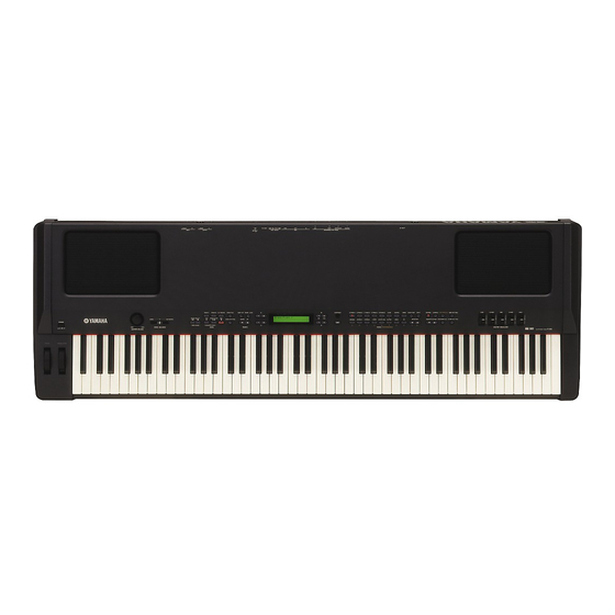
Page 4: Panel Layout(パネルレイアウト
P-250 (パネルレイアウト) PANEL LAYOUT Top Panel (トップパネル) 10 12 13 9 11 [PITCH] wheel [PITCH]ホイール [MODULATION] wheel [MODULATION]ホイール [POWER] switch [POWER]スイッチ [MASTER VOLUME] dial [MASTER VOLUME]ダイアル [SONG BALANCE] control knob [SONG BALANCE]コントロールツマミ SONG SELECT [ ] buttons SONG SELECT [ ]ボタン... - Page 5 P-250 20 21 22 23 24 25 27 28 29 [CONTRAST] knob [CONTRAST]ツマミ [EXIT] button [EXIT]ボタン VOICE/PERFORMANCE buttons VOICE/PERFORMANCEボタン [VOICE EDIT] button [VOICE EDIT]ボタン [SPLIT] button [SPLIT]ボタン [REVERB] button [REVERB]ボタン [CHORUS] button [CHORUS]ボタン [PERFORMANCE] button [PERFORMANCE]ボタン [MIDI SETTING] button [MIDI SETTING]ボタン...
- Page 6 P-250 Rear Panel Controls(リアパネル) 36 37 38 [AC INLET] [AC INLET] ASSIGNABLE FOOT PEDAL jacks ASSIGNABLE FOOT PEDALジャック [1 (SUSTAIN)] [2 (SOSUTENUTO)] [1 (SUSTAIN)] [2 (SOSUTENUTO)] [3 (SOFT)] [4 (AUX)] [3 (SOFT)] [4 (AUX)] MIDI [IN]/[OUT]/[THRU] terminals MIDI [IN]/[OUT]/[THRU]端子 [HOST SELECT] switch [HOST SELECT]スイッチ...
-
Page 7: Disassembly Procedure(分解手順
P-250 (分解手順) DISASSEMBLY PROCEDURE CP ユニットの開け方 Opening Control Panel Unit (所要時間:約 3 分) (Time required: about 3 minutes) 棚板下より、 [240]のネジ6本を外し、 CPユニットの手 前を持ち上げて開けます。 (図 1) Remove the six (6) screws marked [240] located under the keybed. (Fig. 1) ※ このとき、CP ユニットを開けすぎて背面の蝶番を壊... - Page 8 P-250 Side cover L(腕木L) Side cover R(腕木R) Wheel assembly (Pitch Bend)(ホイールAss'y) Wheel assembly (Modulation)(ホイールAss'y) Speaker grille assembly L Control panel unit Speaker grille assembly R (SPグリルAss'y L) (液晶ディスプレイ) (CPユニット) (SPグリルAss'y R) PN-EQ [730A] [730B] [520] [510B] [510B] [120] [510A] [510A]...
- Page 9 P-250 AJK シート AJK Circuit Board (所要時間:約 10 分) (Time required: about 10 minutes) CP ユニットを開けます。 (1 項 参照) A ジャック Ass'y を外します。 (2 項 参照) Open the control panel unit. (See procedure 1.) Remove the A-JACK assembly. (See procedure 2.) [260A]のネジ4本、 [A]のU字金具4個を外し、 AJKシー...
- Page 10 P-250 FU60 Circuit Board FU60 シート (所要時間:約 10 分) (Time required: about 10 minutes) CP ユニットを開けます。 (1 項 参照) Open the control panel unit. (See procedure 1.) FU カバーを外します。 (2 項 参照) (U モデルのみ) FU60Ass'y を外します。 (2 項 参照) Remove the FU cover. (See procedure 2.) (U model only) Remove the FU60 assembly.
- Page 11 P-250 H.P.Ass'y、HP シート Headphones Jack Assembly, HP Circuit Board (所要時間:約 10 分) (Time required: about 10 minutes) CP ユニットを開けます。 (1 項 参照) [250F]のネジ 2 本、 [750A]のネジ 4 本、 [730C]のネジ 1 Open the control panel unit. (See procedure 1.) Remove the two (2) screws marked [250F], the four (4) 本、...
- Page 12 P-250 口金 Ass'y Front Rail Assembly (所要時間:約 10 分) (Time required: about 10 minutes) 12-1 CP ユニットを開けます。 (1 項 参照) 12-2 棚板下側から、 [230]のネジ 8 本を外し、鍵盤前金具 12-1 Open the control panel unit. (See procedure 1.) 12-2 Remove the eight (8) screws marked [230] under the Ass'y と一緒に口金...
- Page 13 P-250 GHD EBUS 鍵盤の分解 Disassembling the Keyboard ※ シートをはずす前に、接点ゴムを歪ませないように、 After inserting a round stick (Rod: TX000670) between the フレームとハンマーの間に丸棒(ロッド:TX000670) frame and the keys, remove the circuit boards. (Fig. 17) を挿入しておきます。 (図 17) Round stick (Rod: TX000670) (丸棒) Fig. 17(図17) 14-1 GHD EBUS L, MK SUB Circuit Board 14-1 GHD EBUS L, MK SUB シート...
- Page 14 P-250 14-4 白鍵 14-4 White key Insert a thin plate between the white keys, near the triangle 薄い金尺状のものを鍵盤の間に挿入して (白鍵盤支点 付近の三角マークの示す方向側の隙間) [D]のストッ mark around the fulcrum of the key, and press down the stopper marked [D] to remove the key. (Fig. 19, Fig. 20) パーを下げ、...
- Page 15 P-250 GHD EBUS 鍵盤の組立 Assembling the Keyboard 15-1 ハンマー白鍵(ハンマー黒鍵) 15-1 Hammer, White Key (Hammer, Black Key) GHD EBUS鍵盤の裏側より、 ハンマー白鍵 (黒鍵) を Place the keyboard assembly upside-down, insert a ham- フレームに差し込み、 ストッパー(L88̲W)を取り付 mer assembly into the frame, and put the stopper (L88_W) けます。 (図 23)...
-
Page 16: Lsi Pin Description(Lsi 端子機能表
P-250 (LSI 端子機能表) LSI PIN DESCRIPTION µ PD780031AYGK-NO1-9ET (XZ916100) LED DRIVER/SWITCH SCAN ········································ 16 µ PD780031AYGK-NO2-9ET (X0031100) LKS ·················································································· 16 HD6417709SHF200B (X2687A00) CPU (SH3) ················································································· 17 T8F02TB-0102 (X0060A00) SWP50 ·································································································· 18 M66291GP (X2156A00) USB Controller ·························································································· 20 PCM1730E-1/2K (X2077A00) DAC (Digital to Analog Converter) ····················································· 20... - Page 17 P-250 HD6417709SHF200B (X2687A00) CPU (SH3) DM: IC014 NAME FUNCTION NAME FUNCTION CK enable / Port K CKE/PTK5 Mode control RAS3L/PTJ0 RAS address bus / Port J Vcc(RTC) Power supply +1.8 V PTJ1 Port J XTAL2 CASL/PTJ2 CAS address bus / Port J...
- Page 18 P-250 T8F02TB-0102 (X0060A00) SWP50 DM: IC012 OUTER OUTER NAME FUNCTION NAME FUNCTION VSS2 Ground VSS2 Ground VDDC Power supply +1.5 V VDDC Power supply +1.5 V CD15 HMA15 CD13 HMA16 Wave memory address bus CD14 HMA22 HMA25 VDDS Power supply +3 V...
- Page 19 P-250 OUTER OUTER NAME FUNCTION NAME FUNCTION AB22 VSS2 Ground VSS2 Ground AC23 VDDC Power supply +1.5 V VDDC Power supply +1.5 V AD24 DMAL1 MELI6 MEL wave data input AE25 DCSL2 MELI7 ADLR Power supply +3 V AF26 DRAS0...
- Page 20 P-250 M66291GP (X2156A00) USB Controller DM: IC002 NAME FUNCTION NAME FUNCTION Core Vcc Core power supply Ground USB data (-) USB data (+) Vbus V bus input Data bus Tr ON Tr ON output TEST TEST input D8/P0 /Dack1 DMA reception signal 1...
- Page 21 P-250 (IC ブロック図) IC BLOCK DIAGRAM TC74VHC14FT (XV890A00) TC74VHC32FT (XY945A00) TC74VHCT245AFT (XT744A00) Hex Inverter Quad 2 Input OR Octal 3-State Bus Transceiver DM: IC006 DM: IC007 DM: IC009, 010 SN75C1168NSR (XU073A00) TC7SU04F (XY447A00) TC7WH32FU(TE12L) (XY364A00) Line Driver/Receiver Inverter Gate Dual 2 Input OR Gate...
-
Page 22: Circuit Boards(シート基板図
P-250 (シート基板図) CIRCUIT BOARDS AJK (X2246B0) ·················································· 23 MK SUB (XZ142B0) ··········································· 34 DJK (X2245C0) ·················································· 33 MV2 (X2244B0) ················································· 22 DM (XZ592H0) ·············································· 24/25 PJK (X3118C0) ·················································· 33 FU60 (XQ395A0) ··············································· 29 PN-EQ (X2507C0) ············································· 28 GHD EBUS L (XZ138D0) ·································· 30 PNL (X2243D0) ··················································... - Page 23 P-250 AJK Circuit Board not installed not installed L/MONO L/MONO INPUT OUTPUT (部品側) Component side (パターン側) Pattern side 2NA-V849970...
- Page 24 P-250 DM Circuit Board not installed to DJK-CN8 not installed to AJK-CN500 not installed to DJK-CN5 not installed to PNL-CN101, to DJK-CN6 not installed PN-EQ-CN10, (部品側) Component side EBUS2 wire harness (to GHD EBUS L-CN1) 2NA-V755310-4...
- Page 25 P-250 DM Circuit Board (パターン側) Pattern side 2NA-V755310-5...
- Page 26 P-250 PNL Circuit Board to DM-CN4, PN-EQ-CN10, EBUS2 wire harness (to GHD EBUS L-CH1) to WHEEL Ass'y TRACK1 SONG SELECT SONG BALANCE NEW SONG SYNCHR 2NA-V845480-1, 2...
- Page 27 P-250 to PNR-CN81 to PNR-CN71 EXTRA TRACK1 TRACK2 TRACKS SONG FILE MIDI OUT PANEL LOCK DOWN START/ SONG SETTING STOP TEMPO SYNCHRO START SONG (部品側) Component side (パターン側) Pattern side 2NA-V845480-1, 2...
- Page 28 P-250 PNR Circuit Board to LCD to DM-CN1 to DM-CN2 to PNL-CN80 GRAND GRAND E.PIANO 1 E.PIANO 2 E.PIANO 3 PIANO 1 PIANO 2 CONTRAST SYNTH. ORGAN 1 ORGAN 2 STRINGS CHOIR EXIT VOICE/PERFORMANCE PN-EQ Circuit Board to PNL-CN101, DM-CN4,...
- Page 29 P-250 to PNL-CN70 HARP- VIBRA- CLAVI. SICHORD PHONE VOICE SPLIT REVERB CHORUS PERFORMANCE MIDI SETTING EDIT VARIATION MASTER EQ EDIT GUITAR BASS OTHER SETTING PERFORM. FILE Component side (部品側) FU60 Circuit Board to Power Transformer (Primary) to POWER Switch not installed...
- Page 30 P-250 GHD EBUS L Circuit Board V851480 Component side (部品側)...
- Page 31 P-250 GHD H Circuit Board to GHD M-CN2 Component side (部品側) 2NAK8-V852140...
- Page 32 P-250 GHD M Circuit Board (部品側) Component side 2NAK8-V852150...
- Page 33 P-250 DJK Circuit Board not installed not installed to DM-CN8 to DM-CN5 to MA60-CN4 to DM-CN3 to DM-CN7 THRU TO HOST MIDI PC-2 MIDI HOST SELECT (部品側) Component side ASSIGNABLE FOOT PEDAL (パターン側) Pattern side PJK Circuit Board ASSIGNABLE FOOT PEDAL...
- Page 34 P-250 MA60 Circuit Board MK SUB Circuit Board not installed to GHD EBUS L-CN5 to GHD EBUS L-CN4 (部品側) Component side to DJK-CN10, not installed AJK-CN540 (部品側) Component side CAUTION: REPLACE WITH SAME TYPE 5A 125V FUSE. ATTENTION: UTILISER UN FUSIBLE DE RECHANGE DE MÉME TYPE DE 5A 125V.
-
Page 35: Test Program(テストプログラム
While pressing the [C#2], [F2] and [G#2] keys, turn on the [POWER] switch. 3. Proceeding through the Test Program When the test program is activated, the sign “TEST P-250” appears on the LCD display. Select the test program item by pressing the [UP ] or [DOWN ] button of [TEMPO]. - Page 36 P-250 LCD (initial) Test Function and Judgment criteria 012:EQ Low Checks the EQ-LOW frequency. Measured value: - 4.0 dBm +/-2 dB Measurement terminal Outputs the sine wave at about 65.4 Hz (C1). (PAN=Center) MA60-CN6 013:EQ Mid Checks the EQ-MID frequency.
- Page 37 P-250 LCD (initial) Test Function and Judgment criteria 032:To Host Chk Short-circuit between pins 3 and 5, pins 6 and 8 of the [TO HOST] terminal and perform the test. Change the [HOST SELECT] switch position according to the LCD indication and check that the following tone is output at each postiion.
- Page 38 [MODULATION]: 最小 MASTER EQ. [LOW]−[HIGH]: 中央 2. テストプログラムの起動 [C2#]と[F2]と[G2#]の鍵盤を同時に押さえながら、 [POWER]スイッチをON にします。 3. テストの進め方 テストプログラムが起動されると、LCD に TEST P-250 と表示されます。 [TEMPO]の[UP ]、 [DOWN ]ボタンを押して、テストプログラムの項目を選択します。 [MIDI OUT]ボタンを押して、テストを実行します。 結果が OK の場合は、再度[MIDI OUT]ボタンを押して項目選択表示に戻します。 [TEMPO]の[UP ]、 [DOWN ]ボタンを押して、次のテスト項目を選択します。 テスト結果が OK だった項目には、項目名の先頭に * (アスタリスク)が表示されます。 テスト結果が NG の場合は、 [SONG SELECT]の[ ]ボタンを押して、項目選択表示に戻します。 その後、 [POWER]スイッチを OFF にして、テストプログラムを終了します。...
- Page 39 P-250 LCD 表示 テスト内容及び判定条件など EQ-LOW 周波数チェック 測定値:-4.0 dBm ± 2 dB 012:EQ Low 測定端子 65.4Hz(C1)の正弦波を PAN =センターで出力します。 MA60-CN6 013:EQ Mid EQ-MID 周波数チェック 測定値:-5.0 dBm ± 2 dB 1 pin: L ch 523Hz(C4)の正弦波を PAN =センターで出力します。 3 pin: R ch EQ-HIGH 周波数チェック 測定値:-2.0 dBm ± 2 dB 014:EQ High 2, 4 pin: GND 4186Hz(C7)の正弦波を PAN =センターで出力します。 015:D/A Noise 押鍵発音時、ビット落ちノイズ等が無いことを確認します。 LCD に D/A Noise OK と表示されます。...
- Page 40 P-250 LCD 表示 テスト内容及び判定条件など [TO HOST]端子の 3 ピンと 5 ピン、6 ピンと 8 ピンをショートし、テストを実行します。LCD に表示さ 032:To Host Chk れる指示にしたがって[HOST SELECT]スイッチを切り替え、各発音を確認します。 (USB は C3、PC- 2 は C4、MAC は C5) チェックの結果が LCD に表示されます。 To Host Chk OK が表示されることを確認します。 USB 端子チェック 033:USB Chk [USB]端子とパーソナルコンピューターをUSBケーブルで接続した後PC側のMIDI-USBドライバーを スルーに設定し、 [HOST SELECT]スイッチを USB にセットしておきます。テストを実行すると、...
-
Page 41: Factory Set(初期化
[POWER] switch to turn on the power す)にしても、 基本設定に戻すことができます。 この場合、 保存用メモリーの中のファイルは消去されません。保存 to the P-250. The files saved in storage memory are not erased. If you wish to erase the files in memory at this time, press and 用メモリーの中のファイルも同時に消去したい場合は、... -
Page 42: Midi Implementation Chart
P-250 MIDI IMPLEMENTATION CHART YAMAHA [ Electronic Piano ] MIDI Implementation Chart Date: 1 July 2002 Model: P-250 Version : 1.0 Function Transmitted Recognized Remarks Basic Default 1–16 1–16 Channel Changed 1–16 1–16 Mode Default Messages Altered ************ Note 0–127 0–127... -
Page 43: Midi Data Format
P–250 MIDI DATA FORMAT Many MIDI messages listed in the MIDI Data Format are expressed in decimal numbers, binary numbers and hexadecimal numbers. Hexadecimal numbers may include the letter “H” as a suffix. Also, “n” can freely be defined as any whole number. To enter data/values, refer to the table below. Decimal Hexadecimal Binary... - Page 44 P–250 MIDI CHANNEL MESSAGE (1) O: available Status byte 1st Data byte 2nd Data byte MIDI Reception (respond/ignore) MIDI Transmission (generated data) PLAY Main MIDI Events Panel Recorded Status Data (HEX) Parameter Data (HEX) Parameter Song Layer Left Keyboard Song MIDI PLAY (main generation method)
- Page 45 P–250 MIDI CHANNEL MESSAGE (2) Parameters controlled by NRPN (Non-Registered Parameter Numbers) NRPN Data Entry MIDI Reception (respond/ignore) MIDI Transmission (generated data) PLAY Main Parameter Data Range Panel Recorded Song Layer Left Keyboard Song MIDI PLAY (main generation method) from panel LeftLayer Vibrato Rate mm : 00H-40H-7FH (-64...0...+63)
- Page 46 P–250 MIDI Parameter Change table (SYSTEM INFORMATION) MIDI Reception (respond/ignore) MIDI Transmission (generated data) PLAY Address Size Data Main Parameter Data Range Panel Recorded Song Layer Left Keyboard Song MIDI PLAY (main generation method) from panel LeftLayer 20-7F Model Name 1 32...127(ASCII CHARACTER) 20-7F Model Name 14...
- Page 47 P–250 MIDI Reception (respond/ignore) MIDI Transmission (generated data) PLAY Address Size Data XG Default Main Parameter Data Range Panel Recorded Song Layer Left Keyboard Song MIDI PLAY (main generation method) from panel LeftLayer 00-7F VARIATION TYPE MSB Refer to Effect Parameter List 05(=DELAY L,C,R) 00-7F VARIATION TYPE LSB...
- Page 48 P–250 MIDI Reception (respond/ignore) MIDI Transmission (generated data) PLAY Address Size Data Main Parameter Data Range Panel Recorded Song Layer Left Keyboard Song MIDI PLAY (main generation method) from panel LeftLayer 00-7F INSERTION EFFECT PARAMETER 1 MSB Refer to Effect Parameter List O (* Depends on Insertion Type) 00-7F INSERTION EFFECT PARAMETER 1 LSB...
- Page 49 P–250 MIDI Reception (respond/ignore) MIDI Transmission (generated data) PLAY Address Size Data XG Default Main Parameter Data Range Panel Recorded Song Layer Left Keyboard Song MIDI PLAY (main generation method) from panel LeftLayer 00-01 Rcv PITCH BEND OFF, ON 00-01 Rcv CH AFTER TOUCH(CAT) OFF, ON 00-01...
- Page 50 – TOTAL SIZE n: Drum Setup Number (0-1) rr: note number (0D-5B) In the following cases, the P-250 will initialize all Drum Setups. XG SYSTEM ON received GM SYSTEM ON received DRUM SETUP RESET received (only when in XG mode) •...
- Page 51 Panel Song Keyboard Song MIDI LeftLayer (main generation method) 50 11 0n 02 dd F7 F0= Exclusive status 11110000 43= YAMAHA ID 01000011 73= Clavinova ID 01110011 String 01= Model ID (Clavinova common ID) 00000001 Resonance 50= SubID 01010000 (Other Setting)
-
Page 52: Parts List
ELECTRONIC PIANO PARTS LIST CONTENTS(目次) SPEAKER BOX ASSEMBLY OVERALL ASSEMBLY(総組立) ······················ 2 (SP BOX Ass’y)··················· 11 KEYBED ASSEMBLY(棚板 Ass’y) ·················· 5 CONTROL PANEL UNIT(CP ユニット)········· 6 KEYBOARD ASSEMBLY A-JACK ASSEMBLY(A ジャック Ass’y)········· 8 (GHD_EBUS 鍵盤) ··············· 12 D-JACK ASSEMBLY(D ジャック Ass’y) ········· 9 MA60 ASSEMBLY(MA60 Ass’y)··················... -
Page 53: Overall Assembly(総組立
P-250 (総組立) OVERALL ASSEMBLY Music rest unit (譜面板ユニット) Wheel assemblly: See page 10. (ホイールAss'y) Control panel unit: See page 6. (CPユニット) DM assembly (DM Ass'y) Power switch assembly (PSW束線) 610c 610a U only 110a 610b 660c 660a 610d 290a 660b FU60 assembly (FU60 Ass'y)... - Page 54 P-250 PART NO. DESCRIPTION 部 品 名 REMARKS REF NO. QTY RANK OVERALL ASSEMBLY 総 組 立 P-250 Overall Assembly 総 組 立 (V948420) Overall Assembly 総 組 立 (V948470) Overall Assembly 総 組 立 (V948490) Overall Assembly 総 組...
- Page 55 V8060400 Pedal Assembly ペ ダ ル A s s y VZ885400 Music Rest Unit 譜 面 板 ユ ニ ッ ト X3173A00 CD-ROM Tools for P-250 CD-ROM C D − R O M VT015700 AC Cord J 2P 2.5m 7A 電...
-
Page 56: Keybed Assembly(棚板 Ass'y
P-250 (棚板 Ass’y) KEYBED ASSEMBLY Keybed sub-assembly (棚板集成) Duct box assembly (ダクトBOX集成) PART NO. DESCRIPTION 部 品 名 REMARKS REF NO. QTY RANK V9486100 KEYBED ASSEMBLY 棚 板 A s s y P-250 Keybed Sub-Assembly 棚 板 集 成 (V948640) ET200070 B 4.0X9.5 MFZN2Y... -
Page 57: Control Panel Unit(Cp ユニット
P-250 (CP ユニット) CONTROL PANEL UNIT... - Page 58 P-250 PART NO. DESCRIPTION 部 品 名 REMARKS REF NO. QTY RANK CONTROL PANEL UNIT C P ユ ニ ッ ト P-250 (V948620) V9633100 Control Panel C P 印 刷 品 VF179400 Bushing Black 譜 面 板 ブ ッ シ ュ...
-
Page 59: A-Jack Assembly(A ジャック Ass'y
P-250 PART NO. DESCRIPTION 部 品 名 REMARKS REF NO. QTY RANK Nonwoven Fablic Cloth M 不 織 布 M (V999670) Nonwoven Fablic Cloth 30X4Xt0.35 不 織 布 (WA04070) Spacer t=0.1 ス ペ ー サ ー (WB03200) Nonwoven Fablic Cloth 200X15Xt0.25... -
Page 60: D-Jack Assembly(D ジャック Ass'y
P-250 (D ジャック Ass’y) D-JACK ASSEMBLY PART NO. DESCRIPTION 部 品 名 REMARKS REF NO. QTY RANK D-JACK ASSEMBLY D ジ ャ ッ ク A s s y P-250 (V963510) V9635900 D-Jack Angle Assembly Dジャック金具Ass y V9594300 Circuit Board D... -
Page 61: Wheel Assembly(ホイール Ass'y
P-250 (ホイール Ass’y) WHEEL ASSEMBLY MODULATION PITCH BEND PART NO. DESCRIPTION 部 品 名 REMARKS REF NO. QTY RANK WHEEL ASSEMBLY ホ イ ー ル A s s y P-250 (V964540) VF536800 Frame フ レ ー ム VJ187600 Frame A フ... -
Page 62: Speaker Box Assembly
P-250 (SP. BOX Ass’y) SPEAKER BOX ASSEMBLY PART NO. DESCRIPTION 部 品 名 REMARKS REF NO. QTY RANK SPEAKER BOX ASSEMBLY SP.BOX Ass y P-250 (WA23080) VP114800 Speaker Box Black S P . B O X XZ346A00 Speaker 13.0cm 8ohm 30W ス... -
Page 63: Keyboard Assembly
P-250 (GHD_EBUS 鍵盤) KEYBOARD ASSEMBLY... -
Page 64: Ghd_Ebus 鍵盤
P-250 PART NO. DESCRIPTION 部 品 名 REMARKS REF NO. QTY RANK V8278500 KEYBOARD ASSEMBLY GHD_EBUS A88 K6 G H D _ E B U S 鍵 盤 P-250 MK Frame フレーム88アウトサート (VU42210) VU101000 White Key 白 鍵 C VU101100 White Key 白... - Page 65 P-250 (MA60 Ass’y) MA60 ASSEMBLY PART NO. DESCRIPTION 部 品 名 REMARKS REF NO. QTY RANK MA60 ASSEMBLY M A 6 0 A s s y P-250 V8816200 MA60 Assembly M A 6 0 A s s y V8816300 MA60 Assembly M...
- Page 66 P-250 (ペダル Ass’y) PEDAL ASSEMBLY • Pedal volume Wiring BL WH RE PART NO. DESCRIPTION 部 品 名 REMARKS REF NO. QTY RANK V8060400 PEDAL ASSEMBLY ペ ダ ル A s s y P-250 V8050800 Pedal Box ペ ダ ル...
-
Page 67: Electrical Parts(電気部品
P-250 (電気部品) ELECTRICAL PARTS PART NO. DESCRIPTION 部 品 名 REMARKS REF NO. QTY RANK ELECTRICAL PARTS 電 気 部 品 P-250 V9442600 Circuit Board A J K シ ー ト (V944250)(X2246B0) V9594300 Circuit Board D J K シ ー... - Page 68 P-250 PART NO. DESCRIPTION 部 品 名 REMARKS REF NO. QTY RANK C0410 UA354270 Mylar Capacitor 0.0270 50V J マ イ ラ ー コ ン C0411 UA353390 Mylar Capacitor 3900P 50V J マ イ ラ ー コ ン C0412 UA353390...
- Page 69 P-250 PART NO. DESCRIPTION 部 品 名 REMARKS REF NO. QTY RANK R0404 RD357150 Carbon Resistor (chip) 15.0K 63M J チ ッ プ 抵 抗 R0405 RD356220 Carbon Resistor (chip) 2.2K 63M J チ ッ プ 抵 抗 R0406 RD357180 Carbon Resistor (chip) 18.0K 63M J...
- Page 70 P-250 PART NO. DESCRIPTION 部 品 名 REMARKS REF NO. QTY RANK IC001 XY447A00 TC7SU04F I C INVERTER IC002 XU073A00 SN75C1168NSR I C LINE DRIVER/RECEIVER IC003 VD473200 Photo Coupler 6N137 フ ォ ト カ プ ラ JK001 VT202500 DIN Connector 5P YKF51-50 D...
- Page 71 P-250 PART NO. DESCRIPTION 部 品 名 REMARKS REF NO. QTY RANK C0020 US062470 Ceramic Capacitor-SL(chip) 470P 50V J チ ッ プ セ ラ ( S L ) C0021 US064100 Ceramic Capacitor-B (chip) 0.0100 50V K チ ッ プ セ ラ ( B )...
- Page 72 P-250 PART NO. DESCRIPTION 部 品 名 REMARKS REF NO. QTY RANK C0120 V9451300 Electrolytic Cap.-OS (chip 68.00 4.0V チ ッ プ O S ケ ミ コ ン C0121 US062470 Ceramic Capacitor-SL(chip) 470P 50V J チ ッ プ セ ラ ( S L )...
- Page 73 P-250 PART NO. DESCRIPTION 部 品 名 REMARKS REF NO. QTY RANK C0231 US064100 Ceramic Capacitor-B (chip) 0.0100 50V K チ ッ プ セ ラ ( B ) C0234 US135100 Ceramic Capacitor-F (chip) 0.1000 16V Z チ ッ プ セ ラ ( F )...
- Page 74 P-250 PART NO. DESCRIPTION 部 品 名 REMARKS REF NO. QTY RANK IC038 X0609A00 LMS8117AMP-ADJ I C REGULATOR IC039 XZ642A00 TAR5S33 I C REGULATOR +3.3V IC040 XZ216A00 MBM29LV160BE90TN-K I C FLASH ROM 16M L0001 V8901200 Chip Solid Inductance BLM21PG221SN1D チップソリッドインダクタ...
- Page 75 P-250 PART NO. DESCRIPTION 部 品 名 REMARKS REF NO. QTY RANK R0143 RD357470 Carbon Resistor (chip) 47.0K 63M J チ ッ プ 抵 抗 R0144 RD357100 Carbon Resistor (chip) 10.0K 63M J チ ッ プ 抵 抗 R0146 RD354680 Carbon Resistor (chip) 68.0 63M J...
- Page 76 P-250 PART NO. DESCRIPTION 部 品 名 REMARKS REF NO. QTY RANK R0273 RD356220 Carbon Resistor (chip) 2.2K 63M J チ ッ プ 抵 抗 R0274 RD356220 Carbon Resistor (chip) 2.2K 63M J チ ッ プ 抵 抗 R0276 RD356220 Carbon Resistor (chip) 2.2K 63M J...
- Page 77 P-250 PART NO. DESCRIPTION 部 品 名 REMARKS REF NO. QTY RANK Jumper Wire 0.55 ジ ャ ン パ ー 線 (VA07890) V6588200 Circuit Board MK SUB M K サ ブ シ ー ト (V658810)(XZ142B0) C0001 US135100 Ceramic Capacitor-F (chip) 0.1000 16V Z...
- Page 78 P-250 PART NO. DESCRIPTION 部 品 名 REMARKS REF NO. QTY RANK C0017 VC694800 Semiconductive Cera. Cap. 0.1000 25V Z 半 導 体 セ ラ コ ン C0018 VN701200 Electrolytic Cap. 1.00 50.0V ケ ミ コ ン P R C0019 VN701200 Electrolytic Cap.
- Page 79 P-250 PART NO. DESCRIPTION 部 品 名 REMARKS REF NO. QTY RANK CN011 VB390100 Connector Base Post PH 5P TE コ ネ ク タ ベ ー ス ポ ス ト D0010 VT332900 Diode 1SS355 TE-17 ダ イ オ ー ド...
- Page 80 P-250 PART NO. DESCRIPTION 部 品 名 REMARKS REF NO. QTY RANK VR300 VN136100 Slide Variable Resistor B 10.0K RS20111D ス ラ イ ド V R <MASTER EQUALIZER> VR400 VN136100 Slide Variable Resistor B 10.0K RS20111D ス ラ イ ド...
- Page 81 P-250 PART NO. DESCRIPTION 部 品 名 REMARKS REF NO. QTY RANK -0084 RD354470 Carbon Resistor (chip) 47.0 63M J チ ッ プ 抵 抗 R0101 RD356100 Carbon Resistor (chip) 1.0K 63M J チ ッ プ 抵 抗 R0102 RD354470 Carbon Resistor (chip) 47.0 63M J...
- Page 82 P-250 PART NO. DESCRIPTION 部 品 名 REMARKS REF NO. QTY RANK D0020 VD631600 Diode 1SS133,176,HSS104 ダ イ オ ー ド -0028 VD631600 Diode 1SS133,176,HSS104 ダ イ オ ー ド D0033 VB941200 Diode 1SS133,1SS176 ダ イ オ ー ド -0038...
- Page 83 P-250 PART NO. DESCRIPTION 部 品 名 REMARKS REF NO. QTY RANK SW021 VV439800 Tact Switch SKQNAJ タ ク ト S W SYNTH.PAD/ 13 <VOICE/PER SW021 V8889300 Push Switch EVQ 11Y 07K プ ッ シ ュ S W SW022 VV439800...
- Page 84 P-250 P-250 OVERALL CIRCUIT DIAGRAM 1/4 (DM) REGULATOR +2.0V REGULATOR +1.5V (+VCC-ADJ) RESET to PNR-CN91 to PNR-CN92 FLASH ROM SDRAM 64M MASK ROM BUFFER to PJK-CN10 to DJK-CN5 to DJK-CN1 to PJK-CN11 FLASH ROM FLASH ROM SDRAM 64M to PNL-CN101,...
- Page 85 P-250 P-250 OVERALL CIRCUIT DIAGRAM 2/4 (GHD EBUS L, MK SUB, GHD M, GHD H, WML, WMH) (A-1 ~ F2 # ) GHD EBUS L MK SUB to PN-EQ-CN10, PNL-CN101, DM-CN4 Not installed not installed 28CC1-8819224 28CC1-8819027 to DM-CN14 (WML)
- Page 86 P-250 P-250 OVERALL CIRCUIT DIAGRAM 3/4 (PNL, PNR, MV2, DJK, PJK, AJK, HP) EQUALIZER INPUT (L/MONO) GRAND GRAND VIBRA- PIANO 1 PIANO 2 E.PIANO 1 E.PIANO 2 E.PIANO 3 CLAVI. /6 HARPSICHORD PHONE VOICE SPLIT REVERB CHORUS PERFOR- EDIT MANCE...
- Page 87 P-250 (ユニットレイアウト & 結線図) P-250 OVERALL CIRCUIT DIAGRAM 4/4 (FU60, MA60, PN-EQ) P-250 CIRCUIT BOARD LAYOUT & WIRING REGULATOR +5V MA60 POWER ON/OFF to DM-CN9 WHEEL Ass'y Power FU60 Transformer REGULATOR +3.3V to DJK-CN10, PN-EQ AJK-CN540 CN10 CN101 CN104 AC cord...
- Page 88 P-250 P-250 BLOCK DIAGRAM (ブロックダイアグラム) IC38 CN12 +VCC-ADJ +5D, DGND to MA60-CN3 VBUS, D-, D+ IC36 +1.5 +1.5D +3.3D CN10 +3.3D to MA60-CN4 +3.3D, DGND +VCC-INT (+3.3D) +3.3D +3.3D RESET RESET 16MHz TR1, 2 3,29,81,134, 21,35,47,59, 145,150,154, 71,85,97,111, TR3,4 163,183,205 +3.3D...