
Related Manuals for Amica PC6400ZH


Summary of Contents for Amica PC6400ZH
- Page 1 PBP4VQ247FN / PC6400ZH PBP4VQ247FN / VH 6040 INSTRUCTION MANUAL CERAMIC HOB IO-HOB-0534 / 8070705 (07.2020 / v2)
-
Page 2: Basic Information
DEAR CUSTOMER, Your hob combines exceptional ease of use with excellent effectiveness. Once you have read the instructions, operating your hob will not be a problem. Before being packed and leaving the factory, the safety and functions of this hob were ca- refully tested. -
Page 3: Table Of Contents
TABLE OF CONTENTS Basic information ....................2 Safety instructions ....................4 Saving energy .......................8 Description of the appliance ................9 Installation......................11 Operation ......................16 Cleaning and routine maintenance ..............22 Emergency procedure..................24 Technical data .....................25... -
Page 4: Safety Instructions
SAFETY INSTRUCTIONS Warning: The appliance and its accessible parts become hot during use. Care should be taken to avoid touching heating elements. Children less than 8 years of age shall be kept away unless continuously supervised. This appliance can be used by children aged from 8 years and above and persons with reduced physical, sensory or mental capabilities or lack of experience and knowledge if they have been given supervision or... - Page 5 SAFETY INSTRUCTIONS Warning: If the surface is cracked, switch off the ap- pliance to avoid the possibillity of electric shock. The appliance is not intended to be operated by me- ans of an external timer or separate remote-control system. You should not use steam cleaning devices to clean the appliance.
- Page 6 SAFETY INSTRUCTIONS ● Before using the ceramic plate for the first time read the Operating Manual carefully as thus you can ensure safe operation and avoid damage to the plate. ● If the ceramic plate is operated near a radio, TV set or other emitting device, please check whether the touch panel works correctly.
- Page 7 SAFETY INSTRUCTIONS ● The heating surface of the ceramic plate is resistant to thermal shock. It is neither hot nor cold-sensitive. ● Avoid dropping objects on the plate. A point hit, for example a falling bottle with spices, may in unfavourable circumstances lead to cracks and splits appearing on your ceramic plate.
-
Page 8: Saving Energy
SAVING ENERGY UNPACKING Everybody who properly The appliance is protected from damage during transpor- uses energy not only saves money but also consciously tation by its packaging. After unpacking please dispose acts in aid of the natural of the packing materials in a environment. -
Page 9: Description Of The Appliance
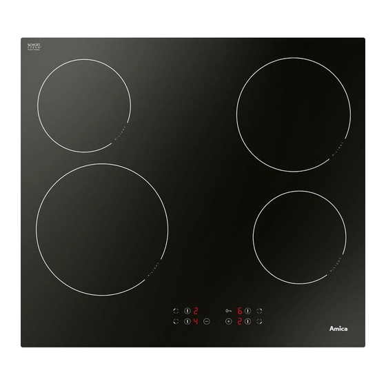
DESCRIPTION OF THE APPLIANCE Description of hob Rear left cooking zone Ø 145mm Double ring rear right cooking zone Ø 180mm Double ring front left cooking zone Ø 210mm Front right cooking zone Ø 145mm Control Panel 1. On/Off/Select a cooking zone 2. - Page 10 DESCRIPTION OF THE APPLIANCE Ceramic hob...
-
Page 11: Installation
INSTALLATION Making the worktop recess • Worktop thickness should be 28 - 40 mm, while its width at least 600 mm. The worktop must be flat and level. Edge of the worktop near the wall must be sealed to prevent ingress of water or other liquids. - Page 12 INSTALLATION Note. When installing the hob in the kit- chen worktop, install a partition panel, as shown on the picture. If the hob is to be installed above a built-in oven, installa- tion of the partition panel is not required. If the hob was installed in the kitchen Installing hob in kitchen cabinet worktop.
- Page 13 INSTALLATION Installing hob - bracket • Use four “A” brackets for 38 mm thick worktops. Fit the hob into worktop opening as shown on figure2 and 3. To properly secure hob in 28 mm thick worktop, use four 15x15x50 mm wooden blocks in addition to “A”...
- Page 14 INSTALLATION Installation of self-adhesive foam gasket * Do not install the appliance without the foam gasket. The gasket must be applied on the appliance as follows: Before fitting the appliance in the kitchen worktop, apply self-adhesive foam gasket provided underneath the rim. - before applying, remove the protective film from the self-adhesive foam gasket - apply the self-adhesive foam gasket underneath the appliance rim (Figure)
- Page 15 INSTALLATION Connecting the plate to the electrical system Note! The plate can be connected to the mains only by a qualified certified installer. Wilful adaptations or modifications to the electric system are prohibited. Guidelines for the installer The plate is factory-set for three-phase alternating current power supply (400 V 3N~50 Hz). It may be adapted for one-phase current power supply (230 V) by adequate bridging on the connection strip, in accordance with the attached wiring diagram.
-
Page 16: Operation
NSTALLATION WIRING DIAGRAM Important! Heating elements operate at 230V. Important! For each connection the protective conductor must Recommended be connected to the terminal connection lead marked 1 230 V single phase connection with H05VV-F3G4 a neutral lead, terminals 1-2-3 are 3X 4 mm bridged, neutral lead to terminal 4, and the protective conductor to... - Page 17 OPERATION The ceramic plate is equipped with sensors operated by touching the marked areas with a finger. Every touch of a sensor is confirmed with a sound. When switching the plate on and off and setting the heating power always touch only one sensor.
- Page 18 OPERATION Control Panel When you connect the appliance to power, Child Lock indicator (5) will be on. Touch and hold the Child Lock sensor (5) until the indicator is off. Now you can use the appliance. No objects should be placed on the sensors (this could cause an error). Touch sensors should be always kept clean.
- Page 19 OPERATION Set the heating power In order to set the heat setting, first select the desired cooking zone using the cooking zone selection sensor (1). Then, when the cooking zone display (2) shows “ ” start setting the desired heat setting using the (+)(4) or (-)(3) sensor field. Switch off selected cooking zone Selected cooking zone may be switched off in the following way: 1.
- Page 20 OPERATION Automatic warm-up function Each cooking zone is equipped with an automatic warm-up function. When this is activated, then the given cooking zone is switched on at full power for a time depending on the heat setting selected, and is then switched back to the heat setting originally set. Activate the automatic warm-up function by setting the required heat setting by touching the (-) (3) sensor first.
- Page 21 OPERATION Residual heat indicator Heat energy that remains accumulated in the cooking zone after cooking is called the resid- ual heat. The appliance displays two different levels of residual heat. When a cooking zone temperature is above 65°C and the cooking zone or the appliance is switched off, the relevant cooking zone display will show the letter "H".
-
Page 22: Cleaning And Routine Maintenance
CLEANING AND ROUTINE MAINTENANCE Daily cleaning and proper maintenance have crucial impact on the durability of your ceramic plate. Clean the ceramic plate observing the same rules as for glass. Never use abrasive or aggressive clean- ing agents, scrubbing powders or scratching sponges. - Page 23 CLEANING AND ROUTINE MAINTENANCE Never apply cleaning agent on a hot hotplate. Caution! Leave the cleaning agent to dry and then If from any reason you are not wipe it off with a wet cloth. Any residuals of able to control the switched on cleaning agents should be wiped off with a plate, switch off the main switch damp cloth before heating the plate for the...
-
Page 24: Emergency Procedure
EMERGENCY PROCEDURE Every time when emergency situation occurs you should: ● switch off the working assemblies of the plate ● disconnect power supply ● call in the service ● as some minor faults can be removed by the user in accordance with the be low specified instructions, before calling the Customer Service please go thro ugh the Table checking every point. -
Page 25: Technical Data
EMERGENCY PROCEDURE PROBLEM CAUSE ACTION 7.Residual temperature in di- - power supply fa ilu re, the -the residual temperature in- ca tor is not lighted although ap plian ce has been di scon- di ca tor will work again after the hot pla tes are still hot nec ted from the mains swit ching the control panel...
Need help?
Do you have a question about the PC6400ZH and is the answer not in the manual?
Questions and answers