ITech IT6700 Series User Manual
Programmable hv power supply
Hide thumbs
Also See for IT6700 Series:
- User manual (13 pages) ,
- Programming manual (46 pages) ,
- User manual (59 pages)

Related Manuals for ITech IT6700 Series


Summary of Contents for ITech IT6700 Series
- Page 1 Programmable HV Power Supply Series IT6700 User’s Manual Model: IT6722/IT6722A/IT6723/IT6723B/ IT6723C/IT6723G/IT6723H/IT6724/ IT6724B/IT6724C/IT6724G/IT6724H/ IT6726B/IT6726C/IT6726G/IT6726H/ IT6726V Version: V3.0...
- Page 2 (including electronic storage and “Caution” signs indicate danger. It is extent of laws, ITECH is not committed retrieval or translation into a foreign required to pay attention to the contents to any explicit or implied guarantee for...
-
Page 3: Limitation Of Warranty
ITECH, and ITECH will be responsible for return freight. ⚫ If the product is sent to ITECH for warranty service from other countries, the customer will be responsible for all the freight, duties and other taxes. Limitation of Warranty ⚫... -
Page 4: Safety Precautions
In case of failure to follow these precautions or specific warnings in other parts of the manual, violation against the safety standards related to the design, manufacture and purpose of the instrument will occur. If the user does not follow these precautions, ITECH will bear no responsibility arising there from. ⚫... -
Page 5: Environmental Conditions
⚫ Do not block the air vent of the equipment. Environmental conditions The IT6700 series power supply can only be used indoors or in low condensation areas. The following table shows general environmental requirements for this instrument. Environmental conditions... -
Page 6: Waste Electrical And Electronic Equipment (Weee) Directive
According to the equipment classification in Annex I of the WEEE directive, this instrument belongs to the “Monitoring” product. If you want to return the unnecessary instrument, please contact the nearest sales office of ITECH. Copyright © Itech Electronic Co., Ltd. -
Page 7: Compliance Information
Connection of the instrument to a test object may produce radiations beyond the specified limit. Use high-performance shielded interface cable to ensure conformity with the EMC standards listed above. Safety Standard IEC 61010-1:2010/ EN 61010-1:2010 Copyright © Itech Electronic Co., Ltd. -
Page 8: Table Of Contents
5.1 RS232 interface ..............................44 5.2 USB interface ..............................45 5.3 RS485 interface ..............................45 5.4 GPIB interface (Only for IT6700(G) series) ......................46 Appendix ................................48 Specifications of Red and Black Test Lines ....................... 48 Copyright © Itech Electronic Co., Ltd. -
Page 9: Chapter I Acceptance And Installation
The package requirements should be met when the instrument is returned to factory for repair. Optional accessories for IT6700 Series power supply available for independent sales: IT-E151/IT-E151A support *IT6726 Series have no optional accessories. -
Page 10: Installation Position
Acceptance and Installation 1.2 Installation Position The instrument should be installed at well-ventilated and rational-sized space. Please select appropriate space for installation based on the power supply size. Model IT6722/IT6722A Detailed dimensional drawings Copyright © Itech Electronic Co., Ltd. - Page 11 Acceptance and Installation IT6723/IT6723B/IT6724/IT6724B Model Detailed dimensional drawings Copyright © Itech Electronic Co., Ltd.
- Page 12 Acceptance and Installation IT6723C/IT6724C Model Detailed dimensional drawings Copyright © Itech Electronic Co., Ltd.
- Page 13 Acceptance and Installation IT6723G/IT6723H/IT6724G/IT6724H Model Detailed dimensional drawings Copyright © Itech Electronic Co., Ltd.
- Page 14 Acceptance and Installation Model IT6726B/IT6726G/IT6726H/IT6726V Detailed dimensional drawings Copyright © Itech Electronic Co., Ltd.
-
Page 15: Installation Of Support
Detailed dimensional drawings 1.3 Installation of support IT6700 Series power can be mounted on a standard 19” rack. ITECH provides user with IT-E151/IT-E151A rack, as an optional mount kit. The detailed operation please refer to the User Manual of your mount kit. - Page 16 Acceptance and Installation AC power input level IT6700 series contains many models. The input level of different model is different. Please refer to the specifications of different models for detailed input power specifications and maximum apparent power specifications. NOTE IT6722, IT6722A, IT6724, IT6724B, IT6724C, IT6724H, IT6726H, IT6724G, IT6726G, IT6726V, IT6726B and IT6726C power supply can also work in 110V±...
-
Page 17: Connecting The Dut
⚫ Always use test lines provided by ITECH to connect the equipment. If test lines from other factories are used, please check that the test line can withstand maximum current. - Page 18 For example, the maximum current is 1,200A, then 4 pieces of 360A red and black lines are required. 4. Directly connect the other end of the red and black lines to the DUT terminal. Copyright © Itech Electronic Co., Ltd.
-
Page 19: Chapter Ii Quick Start
DC power supplied with communication interface. This series of programmable DC power supply can output the maximum voltage or current with a fixed power for customers. IT6700 series power comes with a standard communication interface RS232/USB, both desktop and system-based features, can be designed and tested according to your needs and provide multi-purpose solutions. -
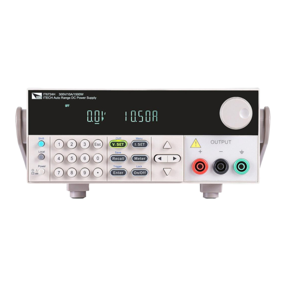
Page 20: Introduction Of Front Panel
Number keys and ESC Function keys UP,DOWN, LEFT and RIGHT key, to move cursor Output terminals ⚫ Front panel of IT6723/IT6723B/IT6723C/IT6724/IT6724B/IT6724C VFD screen Adjusting knob Compound key, the local switch key and power switch Copyright © Itech Electronic Co., Ltd. -
Page 21: Key Introduction
Callback key to call up a set value of system parameters Recall already stored / storage key, to save system parameter /Save settings Meter key, to switch from value set panel and the actual Meter Meter output value Copyright © Itech Electronic Co., Ltd. -
Page 22: Vfd Indicator Description
The power supply has error or Shift Use compound keys Error fault OVP function state on Prot OVP /OTP/OCP Protection OCP function state on Lock Key operation is locked 2.5 Introduction of rear panel ⚫ Rear panel of IT6722 Copyright © Itech Electronic Co., Ltd. - Page 23 IT6724/IT6724C/IT6724G/IT6724H/ IT6724B Cooling fans RS232 Communication interface USB Communication interface GPIB Communication interface (Only for IT6700(G) series) Remote sense terminal and the output terminal Fuse AC power socket ⚫ Rear panel of IT6726H/IT6726G/IT6726V/IT6726B Cooling fans Copyright © Itech Electronic Co., Ltd.
-
Page 24: Power-On Selftest
⚫ To avoid burning out, pay attention to marks of positive and negative polarities before wiring. Selftest steps Normal selftest procedures: Correctly connect the power cord. Press Power key to start up. Copyright © Itech Electronic Co., Ltd. - Page 25 Specification. 3) When install, use a screwdriver to push and turn the fuse box. Refer to the picture below. Copyright © Itech Electronic Co., Ltd.
- Page 26 Quick Start NOTE Fuse of IT6726B/IT6726C/IT6726G/IT6726H/IT6726V can unscrew directly by hand. Copyright © Itech Electronic Co., Ltd.
-
Page 27: Chapter Iii Function And Features
Function and Features Chapter III Function and Features This chapter will introduce the basic operation of IT6700 series power supply, including the following subdivisions: ⚫ Switching of local/remote operation modes ⚫ Voltage setup ⚫ Current setup ⚫ Output on/off operation ⚫... -
Page 28: Output On/Off Operation
Press Enter button to confirm. Recall operating: Recall Recall Press button ( button will lit), and press corresponding group Copyright © Itech Electronic Co., Ltd. -
Page 29: Trigger Operation
Address can be set within 0-30 4800 9600 19200 BAUD 38400 57600 115.2K RS232 COMM NONE 8BIT NONE 8BIT EVEN 8BIT ODD 8BIT SIGNAL MODE Address within 0-30 Select USB communication interface BEEP (ON) Disable the key sound Copyright © Itech Electronic Co., Ltd. - Page 30 Set the power-on output state to be Off. P-OUT (OFF) Set the power-on output state to be the last power-off Keep output state 4800 9600 19200 BAUD COMM RS232 38400 57600 115.2K NONE 8BIT NONE 8BIT Copyright © Itech Electronic Co., Ltd.
- Page 31 P-MEM (RESET) Keep Set the power-on parameter as the last power off state Set the power-on output state to be Off P-OUT (OFF) Keep Set the power-on output state to be the last power-off Copyright © Itech Electronic Co., Ltd.
- Page 32 Set the LIST state as ON LIST LOAD Re-load the LIST file(FILE0-FILE9) Second TIME (SEC) Minute LIST EDIT VSET Set the voltage for present step ISET Set the current for present step Setup single step delay time (0.1-9999) Copyright © Itech Electronic Co., Ltd.
- Page 33 This item can set the power on output state. If you select KEEP item, that indicates the power on output state is the same with output state before this item is set. If you select Off item, unit will automatically in off mode when you Copyright © Itech Electronic Co., Ltd.
- Page 34 This item is used to set the “time on- load” function, time range 0.1-99999S .In ON mode, the indicator light “Timer” will be lit on the VFD screen. When output of power supply is opened, timer will begin to work, after reaching the definite Copyright © Itech Electronic Co., Ltd.
- Page 35 If you select NO, all settings in the menu will remain unchanged. List (List Set) IT6700 series power supply provides 9 list files, each list file includes 150 steps. Before you edit a list file, please set the trigger mode: manual mode. Press...
-
Page 36: Protective Function
STATE item, choose LIST>OFF will enable you to quit list mode. Trigger Trigger 3.10 Protective function The power supply is provided with following protective functions: over-voltage protection (OVP), over-current protection (OCP), over-temperature protection (OTP) and sense reverse protection (SRV). Copyright © Itech Electronic Co., Ltd. -
Page 37: Key Lock Function
Function and Features Over voltage protection (OVP) IT6700 series power supply provide OVP function, press (Shift) + button can enable you to set the over voltage protection level. Over voltage may caused by internal defect or customer’s incorrect operation(such as output voltage rising),or a too high external voltage. - Page 38 In order to ensure the stability of the system, using armored twisted pair cable between the remote sense terminal of IT6700 and load. Please note that the positive and negative polarity when wiring, otherwise it will damage the instrument! Copyright © Itech Electronic Co., Ltd.
-
Page 39: Chapter Iv Technical Specification
Rise time(Full-load) voltage ≤500mS Fall time(No-load) voltage ≤300mS Fall time(Full-load) voltage Transient Response ≤5mS Time voltage1 220V±10% AC Input voltage2 Frequency 47Hz~63Hz voltage 0.01%+20mV Setup stability-30min (%of Output +Offset) current 0.1%+30mA Setup stability-8h voltage 0.01%+20mV Copyright © Itech Electronic Co., Ltd. - Page 40 (%of Output+Offset) ≤0.1%+40mA current Readback accuracy ≤0.03%+20mV voltage (one year 、25° C±5° C) ≤0.1%+40mA (%of Output+Offset) current ≤100mVp-p voltage Ripple (20Hz -20MHz) ≤50mArms current voltage 0.02%+10mV Setup Temp.coefficient (%Output/° C+Offset) current 0.03%+20mA Readback voltage 0.01%+10mV Copyright © Itech Electronic Co., Ltd.
- Page 41 Load regulation voltage (%of Output+Offset) ≤0.1%+10mA current ( change from 10% to 90% of full load) ≤0.01%+30mV Line regulation voltage (%of Output+Offset) ≤0.1%+10mA current ( change from 198-242VAC input) voltage 100mV Setup resolution current 10mA Copyright © Itech Electronic Co., Ltd.
- Page 42 10-600mS Time Power Factor 0.98(Typical) Maximum input current Maximum input 1100VA 2000VA apparent power Storage temperature -10℃~70℃ Protective function OVP/OCP/OTP standard Interface USB/RS232 Isolation 500V (output to ground) Working temperature 0~40℃ Dimension(mm) 214.5mmW×88.2mmH×445mmD Weight(net) Copyright © Itech Electronic Co., Ltd.
- Page 43 Readback voltage 0.03%+10mV stability-30min current 0.1%+60mA (%of Output +Offset) Readback stability-8h voltage 0.03%+10mV (%of Output +Offset) current 0.1%+60mA Efficiency Fuse specification Remote Sense Compensation Command 10-600mS Response Time Power Factor 0.98 Maximum input current Copyright © Itech Electronic Co., Ltd.
- Page 44 ≤5S Fall time(No-load) voltage ≤200mS Fall time(Full-load) voltage Transient Response ≤500uS Time voltage1 110V±10% 220V±10% AC Input voltage2 220V±10% Frequency 47HZ-63HZ voltage 0.03%+200mV Setup stability-30min (%of Output +Offset) current 0.1%+20mA Setup stability-8h voltage 0.03%+200mV Copyright © Itech Electronic Co., Ltd.
- Page 45 (%of Output+Offset) ≤0.1%+20mA current Readback accuracy ≤0.03%+200mV voltage (one year 、25° C±5° C) ≤0.1%+20mA (%of Output+Offset) current ≤250mVp-p voltage Ripple (20Hz -20MHz) ≤40mArms current voltage 0.02%+100mV Setup Temp.coefficient (%Output/° C+Offset) current 0.03%+20mA Readback voltage 0.02%+100mV Copyright © Itech Electronic Co., Ltd.
- Page 46 Load regulation voltage (%of Output+Offset) ≤0.1%+10mA current ( change from 10% to 90% of full load) ≤0.01%+40mV Line regulation voltage (%of Output+Offset) ≤0.1%+10mA current ( change from 198-242VAC input) voltage 100mV Setup resolution current 10mA Copyright © Itech Electronic Co., Ltd.
- Page 47 Response Time Power Factor 0.98 Maximum input current Maximum input 3700VA apparent power Storage temperature -10℃~70℃ Protective function OVP/OCP/OTP standard Interface USB/RS232 Isolation 500V (output to ground) Working temperature 0~40℃ Dimension(mm) 482.5mmW×88.2mmH×548.9mmD Weight(net) 16Kg Copyright © Itech Electronic Co., Ltd.
- Page 48 0.03%+30mV (%of Output +Offset) current 0.2%+60mA Readback voltage 0.03%+30mV stability-30min current 0.2%+60mA (%of Output +Offset) Readback stability-8h voltage 0.03%+30mV (%of Output +Offset) current 0.2%+60mA Efficiency Fuse specification Remote Sense Compensation Command Response 10-600mS Copyright © Itech Electronic Co., Ltd.
- Page 49 0.03%+10mA (%Output/° C+Offset) ≤500mS ≤500mS Rise time(No-load) voltage ≤2S ≤2S Rise time(Full-load) voltage ≤10S ≤10S Fall time(No-load) voltage ≤400mS ≤400mS Fall time(Full-load) voltage Transient Response ≤500uS Time voltage1 220V±10% AC Input voltage2 Frequency 47HZ-63HZ Copyright © Itech Electronic Co., Ltd.
- Page 50 10mA Setup accuracy ≤0.04%+200mV voltage (one year 、25° C±5° C) ≤0.1%+20mA (%of Output+Offset) current Readback accuracy ≤0.04%+200mV voltage (one year 、25° C±5° C) ≤0.1%+20mA (%of Output+Offset) current ≤600mVp-p voltage Ripple (20Hz -20MHz) ≤50mArms current Copyright © Itech Electronic Co., Ltd.
- Page 51 Storage temperature -10℃~70℃ Protective function OVP/OCP/OTP standard Interface USB/RS232 Isolation 1200V (output to ground) Working temperature 0~40℃ Dimension(mm) 482.5mmW×88.2mmH×548.9mmD Weight(net) 16Kg *The above specifications may be subject to change without prior notice. Copyright © Itech Electronic Co., Ltd.
-
Page 52: Chapter V Remote Operation Mode
Operation Mode Chapter V Remote Operation Mode IT6700 series power supply is provided with three communication interfaces to communicate with a computer for selection, including RS232, USB, and RS485. The communication interfaces of different models of series IT6700 are different. -
Page 53: Usb Interface
Access the menu tree Menu → SYST SET → COMM → RS485 to set the RS485 settings. User can set the following parameters of the RS485 interface: Copyright © Itech Electronic Co., Ltd. -
Page 54: Gpib Interface (Only For It6700(G) Series)
IEEE488 bus, must be full access and tighten the screws. Then set the address, the address range of the power : 0 to 30, can set by the I-set I-set function key on the front panel, press the (Shift)+ key to enter the Copyright © Itech Electronic Co., Ltd. - Page 55 Remote Operation Mode system menu function, find the GPIB address setting by button, type the address, key to confirm. GPIB address is stored in nonvolatile memory line. Copyright © Itech Electronic Co., Ltd.
-
Page 56: Appendix
Specifications of Red and Black Test Lines ITECH provides you with optional red and black test lines, which individual sales and you can select for test. For specifications of ITECH test lines and maximum current values, refer to the table below. - Page 57 Contact Us Thanks for purchasing ITECH products. In case of any doubts, please contact us as follows: 1. Visit ITECH website: www.itechate.com 2. Select the most convenient contact method, for further information.
Need help?
Do you have a question about the IT6700 Series and is the answer not in the manual?
Questions and answers