
Related Manuals for ITech IT6722


Summary of Contents for ITech IT6722
- Page 1 Programmable HV Power Supply Series IT6700 User’s Manual Model: IT6722/IT6722A/IT6723/IT6723B/ IT6723C/IT6723G/IT6723H/IT6724/ IT6724B/IT6724C/IT6724G/IT6724H/ IT6726B/IT6726C/IT6726G/IT6726H/ IT6726V Version: V2.1...
- Page 2 (including electronic storage and “Caution” signs indicate danger. It is extent of laws, ITECH is not committed retrieval or translation into a foreign required to pay attention to the contents to any explicit or implied guarantee for...
-
Page 3: Limitation Of Warranty
ITECH, and ITECH will be responsible for return freight. If the product is sent to ITECH for warranty service from other countries, the customer will be responsible for all the freight, duties and other taxes. Limitation of Warranty ... -
Page 4: Safety Precautions
In case of failure to follow these precautions or specific warnings in other parts of the manual, violation against the safety standards related to the design, manufacture and purpose of the instrument will occur. If the user does not follow these precautions, ITECH will bear no responsibility arising therefrom. ... -
Page 5: Waste Electrical And Electronic Equipment (Weee) Directive
According to the equipment classification in Annex I of the WEEE directive, this instrument belongs to the “Monitoring” product. If you want to return the unnecessary instrument, please contact the nearest sales office of ITECH. Copyright © Itech Electronics Co., Ltd. -
Page 6: Compliance Information
Connection of the instrument to a test object may produce radiations beyond the specified limit. Use high-performance shielded interface cable to ensure conformity with the EMC standards listed above. Safety Standard IEC 61010-1:2010/ EN 61010-1:2010 Copyright © Itech Electronics Co., Ltd. -
Page 7: Table Of Contents
Remote Operation Mode ......................44 5.1 RS232 interface ............................. 44 5.2 USB interface ..............................45 5.3 RS485 interface ............................. 45 5.4 GPIB interface ............................... 47 Appendix ................................48 Specifications of Red and Black Test Lines ......................48 Copyright © Itech Electronics Co., Ltd. -
Page 8: Certification And Quality Assurance
The package requirements should be met when the instrument is returned to factory for repair. Optional accessories for IT6700 Series power supply available for independent sales: IT-E151 support *IT6726 Series have no optional accessories. Copyright © Itech Electronics Co., Ltd. -
Page 9: Environmental Conditions
The instrument should be installed at well-ventilated and rational-sized space. Please select appropriate space for installation based on the power supply size. Model IT6722/IT6722A Overall dimensions Width: 255 mm Height: 108.7 mm Depth: 376.37 mm Detailed dimensional drawings Copyright © Itech Electronics Co., Ltd. -
Page 10: Regulation Tag
Acceptance and Installation Model IT6723G/IT6723H/IT6724H Overall dimensions Width: 255 mm Height: 108.7 mm Depth: 466.5 mm Detailed dimensional drawings Copyright © Itech Electronics Co., Ltd. - Page 11 Acceptance and Installation IT6723/IT6723B/IT6723C/ Model IT6724/IT6724B/IT6724C/IT6724G Overall dimensions Width: 255 mm Height: 108.7 mm Depth: 520 mm Detailed dimensional drawings Copyright © Itech Electronics Co., Ltd.
- Page 12 Acceptance and Installation Model IT6726B/IT6726G/IT6726H/IT6726V Overall dimensions Width: 482.5 mm Height: 98.7 mm Depth: 549 mm Detailed dimensional drawings Copyright © Itech Electronics Co., Ltd.
- Page 13 Acceptance and Installation Model IT6726C Overall dimensions Width: 482.5 mm Height: 98.55 mm Depth: 600.55 mm Detailed dimensional drawings Copyright © Itech Electronics Co., Ltd.
-
Page 14: Installation Of Support
1 (support). Installation drawing: Accessory 1 Accessory 2 Fig. 1.1 Front View for Installing One Instrument on Support Fig. 1.2 Front View for Installing Two Instruments on Support Copyright © Itech Electronics Co., Ltd. -
Page 15: Installation Of Power Cord
Connect power cord of standard accessories and ensure that the power supply is under normal power supply. AC power input level Working voltage for IT6723/IT6723B/IT6723C/IT6723G/IT6723H is 110V and 220V; Working voltage for IT6722/IT6722A/IT6724/IT6724B/IT6724C/ IT6724H/IT6726H/IT6724G/IT6726G/IT6726V/IT6726B/IT6726C is 220V, so please pay attention to the working input voltage. AC power input level: ... - Page 16 Connect the three terminals red to line (L), black to neutral (N), and yellow to ground (G) on the other end of the power cord to your AC distribution panel. Copyright © Itech Electronics Co., Ltd.
-
Page 17: Chapter Ii Quick Start
IT6724G 600V 1500W IT6724H 300V 1500W IT6726B 160V 3000W IT6726C 220A 3000W IT6726G 600V 3000W IT6726H 300V 3000W IT6726V 1200V 3000W *IT6722A has not standard GPIB communication interface. *IT6726C has standard RS485 communication interface. Copyright © Itech Electronics Co., Ltd. -
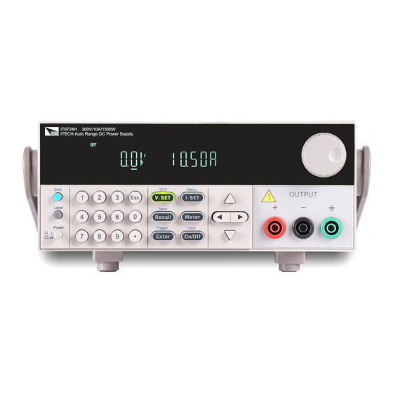
Page 18: Introduction Of Front Panel
Front panel of IT6723/IT6723B/IT6723C/IT6724/IT6724B/IT6724C/IT6724G VFD screen Adjusting knob Compound key, the local switch key and power switch Number keys and ESC Function keys UP,DOWN, LEFT and RIGHT key, to move cursor Protective cover Output terminals Copyright © Itech Electronics Co., Ltd. -
Page 19: Key Introduction
Output on (off) keys, control power output state / keypad On/Off /Lock lock function keys, used to lock the panel buttons Left and right movement keys, used to set the value, to adjust the cursor to the specified location Copyright © Itech Electronics Co., Ltd. -
Page 20: Vfd Indicator Description
OCP function state on Lock Key operation is locked 2.5 Introduction of rear panel Rear panel of IT6722 RS232 Communication interface USB Communication interface GPIB Communication interface Remote sense terminal and the output terminal Cooling fans Copyright © Itech Electronics Co., Ltd. - Page 21 GPIB Communication interface Remote sense terminal and the output terminal Fuse AC power socket Rear panel of IT6726H/IT6726G/IT6726V/IT6726B Cooling fans RS232 Communication interface USB Communication interface GPIB Communication interface factory using terminal Fuse Copyright © Itech Electronics Co., Ltd.
-
Page 22: Power-On Selftest
Do not use terminal board without protective grounding. Before operation, be sure that the power supply is well grounded. To avoid burning out, pay attention to marks of positive and negative polarities before wiring. Copyright © Itech Electronics Co., Ltd. - Page 23 Please replace with a fuse of the same specification. 2) If the fuse is fused, please change fuse of same specification based on machine model. See the table blow for matching information of fuse and machine model. Copyright © Itech Electronics Co., Ltd.
-
Page 24: Output Checkout
Ensure that the voltage can be adjusted from zero to the full rated value. ----End Current Output checkout Turn on the power supply. On/Off Press key to ensure that the output is disabled. At the same time, the OFF status mark is on the VFD. Copyright © Itech Electronics Co., Ltd. - Page 25 0v, and the current on it is close to the value you set. Make sure that the current can be adjusted from 0 to full rated value. Turn off the output of the power supply, and remove the short wire. ----End Copyright © Itech Electronics Co., Ltd.
-
Page 26: Chapter Iii Function And Features
This indicates that you can set current. There are three ways to set output current through front panel. I-set I-set The first way: press ,adjust cursor location through Copyright © Itech Electronics Co., Ltd. -
Page 27: Output On/Off Operation
Press Enter button to confirm. Recall operating: Recall Recall Press button ( button will lit), and press corresponding group Copyright © Itech Electronics Co., Ltd. -
Page 28: Trigger Operation
Address can be set within 0-30 4800 9600 19200 BAUD 38400 57600 115.2K RS232 COMM (GPIB) NONE 8BIT NONE 8BIT EVEN 8BIT ODD 8BIT SIGNAL MODE Address within 0-30 Select USBcommunication interface BEEP (ON) Disable the key sound Copyright © Itech Electronics Co., Ltd. - Page 29 Set the power-on output state to be Offt P-OUT (OFF) Set the power-on output state to be the last power-off Keep output state GPIB ADDR Address can be set within 0-30 4800 COMM (GPIB) 9600 RS232 BAUD 19200 38400 Copyright © Itech Electronics Co., Ltd.
- Page 30 Set the max voltage output limit OCP SET Disable the OCP function Enable the OCP function CHANG Enable the charge-mode function MODE Disable the charge-mode function SYST SET P-MEM Reset Power on parameter is restored to factory setting Copyright © Itech Electronics Co., Ltd.
- Page 31 EXIT Quit the menu setting LIST SET Set the LIST state as OFF LIST STATE Set the LIST state as ON LIST LOAD Re-load the LIST file(FILE0-FILE9) Second TIME LIST EDIT (SEC) Minute Copyright © Itech Electronics Co., Ltd.
- Page 32 This function is used for IT6726C power to battery charging. When ON option is selected, the power output is turned off after completing the battery charge, meanwhile the power will not reverse current, that is to say the battery will not Copyright © Itech Electronics Co., Ltd.
- Page 33 The default set is MANU option. Memory Group Set (MEM GROUP) Power supply can save some often-used parameters in a nonvolatile memory(capacity is 9*8 groups).This function can make the operations more Copyright © Itech Electronics Co., Ltd.
- Page 34 Operation steps: I-set I-set (Menu)button to enter the menu. Press (Shift) + Enter VFD display >MAX VOLT,press to select >LIST SET,press to confirm VFD display >LIST STATE,press to select >LIST EDIT, press Enter to confirm. Copyright © Itech Electronics Co., Ltd.
- Page 35 Enter button to open the output.Now you only need to press (Shift)+ (Trigger) to give a trigger signal,the list file can be ran. Quit list file Copyright © Itech Electronics Co., Ltd.
-
Page 36: Ovp Function
Vo+, Vo- : output terminals, the same with front pannel output terminals; Vs+, Vs- : remote sense pins. NC, NC : No conjunction. Copyright © Itech Electronics Co., Ltd. - Page 37 In order to ensure the stability of the system, using armored twisted pair cable between the remote sense terminal of IT6700 and load. Please note that the positive and negative polarity when wiring, otherwise it will damage the instrument! Copyright © Itech Electronics Co., Ltd.
-
Page 38: Chapter Iv Technical Specification
176V~ 264V AC Input voltage2 Frequency 47Hz~63Hz voltage 0.01%+20mV Setup stability-30min (%of Output +Offset) current 0.1%+30mA Setup stability-8h voltage 0.01%+20mV (%of Output +Offset) current 0.1%+30mA Readback voltage 0.01%+20mV stability-30min current 0.1%+30mA (%of Output +Offset) Copyright © Itech Electronics Co., Ltd. - Page 39 ≤50mArms (20Hz -20MHz) current voltage 0.02%+10mV Setup Temp.coefficient (%Output/°C+Offset) current 0.03%+20mA Readback voltage 0.01%+10mV Temp.coefficient current 0.03%+20mA (%Output/°C+Offset) ≤300mS Rise time(No-load) voltage ≤500mS Rise time(Full-load) voltage ≤5S Fall time(No-load) voltage ≤150mS Fall time(Full-load) voltage Copyright © Itech Electronics Co., Ltd.
- Page 40 10mA voltage 100mV Readback resolution current 10mA ≤0.03%+100mV Setup accuracy voltage 0.03%+100mV (one year 、25°C±5°C) ≤0.1%+20mA ±(%of Output+Offset) current 0.1%+20mA Readback accuracy ≤0.03%+200mV voltage 0.03%+200mV (one year 、25°C±5°C) ≤0.1%+20mA ±(%of Output+Offset) current 0.1%+20mA Copyright © Itech Electronics Co., Ltd.
- Page 41 500V (output to ground) Working temperature 0~40℃ 214.5mmW×88.2mmH×445mmD Dimension(mm) Weight(net) Parameters IT6723C IT6724C voltage 0~32V Rated values current 0~110A ( 0 °C-40 °C) power 850W 1500W ≤0.01%+5mV Load regulation voltage ±(%of Output+Offset) ≤0.1%+10mA current Copyright © Itech Electronics Co., Ltd.
- Page 42 Fuse specification Remote Sense Compensation Command 10-600mS Response Time Power Factor 0.98 Maximum input current Maximum input 1100VA 2000VA apparent power Storage temperature -10℃~70℃ Protective function OVP/OCP/OTP standard Interface GPIB/USB/RS232 Isolation 500V (output to ground) Copyright © Itech Electronics Co., Ltd.
- Page 43 (%of Output +Offset) current 0.1%+20mA Setup stability-8h voltage 0.03%+200mV (%of Output +Offset) current 0.1%+20mA Readback voltage 0.03%+200mV stability-30min current 0.1%+20mA (%of Output +Offset) Readback stability-8h voltage 0.03%+200mV (%of Output +Offset) current 0.1%+20mA Efficiency Fuse specification Copyright © Itech Electronics Co., Ltd.
- Page 44 Readback voltage 0.02%+100mV Temp.coefficient current 0.03%+20mA (%Output/°C+Offset) ≤300mS Rise time(No-load) voltage ≤1S Rise time(Full-load) voltage ≤5S Fall time(No-load) voltage ≤150mS Fall time(Full-load) voltage Transient Response ≤500uS Time voltage1 110V±10% 220V±10% AC Input voltage2 220V±10% Copyright © Itech Electronics Co., Ltd.
- Page 45 10mA ≤0.03%+200mV Setup accuracy voltage (one year 、25°C±5°C) ≤0.1%+40mA ±(%of Output+Offset) current Readback accuracy ≤0.03%+200mV voltage (one year 、25°C±5°C) ≤0.1%+40mA ±(%of Output+Offset) current ≤250mVp-p Ripple voltage ≤50mArms (20Hz -20MHz) current Setup Temp.coefficient voltage 0.02%+100mV Copyright © Itech Electronics Co., Ltd.
- Page 46 0~32V Rated values current 0~220A ( 0 °C-40 °C) power 3000W ≤0.01%+50mV Load regulation voltage ±(%of Output+Offset) ≤0.1%+30mA current ≤0.01%+50mV Line regulation voltage ±(%of Output+Offset) ≤0.1%+10mA current voltage 10mV Setup resolution current 10mA Copyright © Itech Electronics Co., Ltd.
- Page 47 10-600mS Time Power Factor 0.98 Maximum input current Maximum input 3700VA apparent power Storage temperature -10℃~70℃ Protective function OVP/OCP/OTP standard Interface GPIB/USB/RS232 Isolation 500V (output to ground) Working temperature 0~40℃ 482.5mmW×88.2mmH×548.9mmD Dimension(mm) 16Kg Weight(net) Copyright © Itech Electronics Co., Ltd.
- Page 48 (%of Output +Offset) current 0.1%+20mA 0.1%+30mA Readback voltage 0.03%+200mV 0.03%+200mV stability-30min current 0.1%+20mA 0.1%+30mA (%of Output +Offset) Readback stability-8h voltage 0.03%+200mV 0.03%+200mV (%of Output +Offset) current 0.1%+20mA 0.1%+30mA Efficiency Fuse specification Remote Sense Compensation Command 10-600mS Copyright © Itech Electronics Co., Ltd.
- Page 49 Rise time(No-load) voltage ≤2S Rise time(Full-load) voltage ≤10S Fall time(No-load) voltage ≤400mS Fall time(Full-load) voltage Transient Response ≤500uS Time voltage1 220V±10% AC Input voltage2 Frequency 47HZ-63HZ voltage 0.04%+200mV Setup stability-30min (%of Output +Offset) current 0.1%+20mA Copyright © Itech Electronics Co., Ltd.
-
Page 50: Supplementary Parameters
(output to ground) Working temperature 0~40℃ 482.5mmW×88.2mmH×548.9mmD Dimension(mm) 16Kg Weight(net) *The above specifications may be subject to change without prior notice. 4.2 Supplementary parameters Memory: 9×8 groups Suggested calibration frequency: 1time/year Radiating mode :Fans Copyright © Itech Electronics Co., Ltd. -
Page 51: Chapter V Remote Operation Mode
DB-9(not blank modem cable). Base Description number No conjunction TXD, data transmission RXD, data receiving RS232 Pins of Plug No conjunction GND, grounding No conjunction CTS, clear to send RTS, request to send No conjunction Copyright © Itech Electronics Co., Ltd. -
Page 52: Usb Interface
30 units (If connecting more than 10 units, add a 120Ω resistor terminator to the last unit as shown in the figure below). Access the menu tree Menu → SYST SET → COMM → RS485 to set the RS485 settings. Copyright © Itech Electronics Co., Ltd. - Page 53 RS485 can be controlled by one PC by using the commands specific for multi-unit connection. See “Programming Guide” section for details. The following diagram shows how to connect the power supply by using RS485. Connect to PC Copyright © Itech Electronics Co., Ltd.
-
Page 54: Gpib Interface
(Shift)+ key to enter the ▼ ▼ system menu function, find the GPIB address setting by button, type the Enter Enter address, key to confirm. GPIB address is stored in nonvolatile memory line. Copyright © Itech Electronics Co., Ltd. -
Page 55: Appendix
Specifications of Red and Black Test Lines ITECH provides you with optional red and black test lines, which individual sales and you can select for test. For specifications of ITECH test lines and maximum current values, refer to the table below. - Page 56 Contact Us Thanks for purchasing ITECH products. In case of any doubts, please contact us as follows: 1. Refer to accompanying data disk and relevant manual. 2. Visit ITECH website:www.itechate.com 3. Select the most convenient contact method, for further information.
Need help?
Do you have a question about the IT6722 and is the answer not in the manual?
Questions and answers