Table of Contents
Advertisement
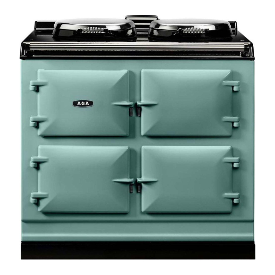
AGA SIX-FOUR SERIES - DC6 (FFD)
(NATURAL GAS AND PROPANE GAS)
WARNING: If the information in this manual is not followed exactly, a fire or
explosion may result causing property damage,personal injury or death.
Do not store or use gasoline or other flammable vapors and liquids in the vicinity
of this or any other appliance.
WHAT DO YOU DO IF YOU SMELL GAS
.
Do not try to light any appliance.
.
Do not touch any electrical switch
.
Do not use any phone in your building.
.
Immediately call your gas supplier from a neighbors phone.
Follow the gas suppliers instructions
.
If you can not reach your gas supplier call the fire department.
Installation and service must be performed by a qualified installer, service
agency or the gas supplier.
Servicing, Installation & Users
Remember, when replacing a part on this appliance, use only spare parts that you can be
assured conform to the safety and performance specification that we require. Do not use
reconditioned or copy parts that have not been clearly authorised by AGA.
PLEASE READ THESE INSTRUCTIONS BEFORE USING THIS APPLIANCE
INSTALLER: LEAVE THESE INSTRUCTIONS WITH THE APPLIANCE
CUSTOMER: KEEP THESE INSTRUCTIONS FOR FUTURE REFERENCE
OWNERS MANUAL
Comprising
Instructions
&
Cooking Guide
For use in USA/Canada
03/08 EINS 514735
Advertisement
Table of Contents

Related Manuals for AGA 6-4 Series


Summary of Contents for AGA 6-4 Series
-
Page 1: Owners Manual
AGA SIX-FOUR SERIES - DC6 (FFD) (NATURAL GAS AND PROPANE GAS) WARNING: If the information in this manual is not followed exactly, a fire or explosion may result causing property damage,personal injury or death. Do not store or use gasoline or other flammable vapors and liquids in the vicinity of this or any other appliance. -
Page 2: Table Of Contents
CONTENTS SECTION INSTALLATION SECTION TECHNICAL DATA INSTALLATION FITTING AND PRODUCT DIMENSIONS ELECTRICAL CONNECTION CONNECTING TO GAS LOCATION COOKER STABILITY PRESSURE TESTING LEVELLING AND MOBILITY WHEELS FITTING OF HOTPLATE CASTINGS AND PAN SUPPORTS SPLASHBACK USERS GUIDE GENERAL INFORMATION SAFETY PRECAUTIONS AND HINTS PRODUCT VIEW CONTROL PANEL GAS HOTPLATE... -
Page 3: Installation Section
Installation Section Remember, when replacing a part on this appliance, use only spare parts that you can be assured conform to the safety and performance specification that we require. Do not use reconditioned or copy parts that have not been clearly authorised by AGA. CAUTION: THIS UNIT IS HEAVY, PROPER EQUIPMENT AND ADEQUATE MANPOWER MUST BE USED IN MOVING THE RANGE TO... -
Page 4: Burner Type
HOTPLATE NATURAL GAS L.H.F. BURNER TYPE ULTRA-RAPID RAPID MAXIMUM HEAT 4.5 kW INPUT BTU’s/hr 15,350 INJECTOR MARKING MAIN 80Hi SECONDARY 2 x 1.30 PRESSURE POINT POSITION: REAR RH SIDE OF HOTPLATE PRESSURE SETTING: 4” W.G. BURNER IGNITION: H.T. SPARK PROPANE L.H.F. -
Page 5: Installation
INSTALLATION CAUTION: THIS INSTALLATION MUST CONFORM WITH LOCAL CODES OR, IN THE ABSENCE OF LOCAL CODES WITH THE NATIONAL FUEL GAS CODE, ANSI Z223.I/NFPA 54 AND NATIONAL ELECTRICAL CODE ANSI/NFPA 70 (IN CANADA CAN/CGA-B149) AND ONLY USED IN A WELL VENTILATED SPACE, READ THESE INSTRUCTIONS BEFORE INSTALLING OR USING THIS APPLIANCE. -
Page 6: Fitting And Product Dimensions
FITTING AND PRODUCT DIMENSIONS Any side wall above the cooker on either side shall be not less than 3” (75mm) horizontally from the cooker (Fig. 1). Combustible surfaces over the top of the cooker must not be closer than 28” (711mm) and must not exceed 13”... -
Page 7: Electrical Connection
ELECTRICAL CONNECTION Electrical Grounding is required on this appliance. Do Not connect to the electrical supply until the appliance is permanently grounded. Disconnect the power to the junction box before making the electrical connection. This appliance must be connected to a grounded, metallic, permanent supply or a grounding connector should be connected to the grounding terminal or wire lead on the appliance. -
Page 8: Electrical Connection
ELECTRICAL CONNECTION (continued) ELECTRICAL CONNECTION IS LOCATED AT THE TOP RIGHT HAND SIDE OF THE APPLIANCE, BEHIND SIDE PANEL. DURING INSTALLATION REMOVE THE RIGHT HAND SIDE PANEL TO CONNECT ELECTRICAL SUPPLY. Remove 6 screws securing side panel to gain access to mains terminal. See Fig. 3 for location of cover. -
Page 9: Wiring Diagram
WIRING DIAGRAM CONNECTING TO GAS CAUTION: ENSURE THAT THE COOKER IS ISOLATED FROM ELECTRIC SUPPLY The cooker can be installed with an approved flexible connection. Supply piping should not be less than 3/8 I/D Flexiline. Connection is made to the 1/2” NPT female thread located just below the hotplate level on the right hand side of the cooker. -
Page 10: Location
LOCATION This appliance must be installed on 1/8” thick Commercial Grade Vinyl composition floor finishing materials or equivalent. Combustible side wall clearance above the hotplate shall be greater than 3”. Surfaces over the top of the range must not be closer than 28” and must not exceed 13” in depth. The vent slots in the back of the top plate (or shroud) must not be obstructed. -
Page 11: Cooker Stability
A stability bracket shall be secured firmly to the fabric of the building. For positioning of bracket (See Fig. 3). A safety chain should also be anchored firmly to the wall and cooker to prevent strain on the gas connection, when the cooker is withdrawn for servicing. When fitting a stability bracket and chain refer to Fig. -
Page 12: Pressure Testing
POSITION OF GAS VALVE ON WALL (locate in shaded areas) IMPORTANT: THE GAS SUPPLY CONNECTION AT THE WALL MUST NOT PROJECT OUT FROM THE WALL BY MORE THAN 1 INTERFERE WITH THE BACK OF THE COOKER. Fig. 4 PRESSURE TESTING The maximum gas inlet pressure to the appliance must not exceed 10”... -
Page 13: Levelling And Mobility Wheels
LEVELLING AND MOBILITY WHEELS INSTALLATION/LEVELLING The 6-4 Series is designed to stand on a flat and level surface, however, any unevenness may be overcome by adjusting the four levelling feet, one at each corner of the base plate. The adjusting screws are accessed by removing left and right hand hotplate castings (See section ‘To Remove Hotplate Castings - Servicing Section Page 48). -
Page 14: Fitting Of Hotplate Castings And Pan
FITTING OF HOTPLATE CASTING AND PAN SUPPORTS HOTPLATE CASTINGS 1. Attach earth cable from centre casting to cooker chassis and locate over burner bodies. Repeat for LH and RH castings and that the gaskets are fitted where the outer castings overlap centre castings. -
Page 15: Wok Burner
3. Fit and secure six burner rings using M4 screws on rear left hand, front centre, front right hand and rear right hand burners. Use No.6 3/8 screw on front left hand and centre rear burners. (See Fig. 6C). NOTE: The fitting of LH and centre burners are the same as shown in Fig. 6B. Fig. - Page 16 ASSEMBLY OF RAPID AND SEMI-RAPID BURNERS BURNER CAP BURNER HEAD ELECTRODE Fig. 7B FITTING BURNER CAP - RAPID AND SEMI-RAPID BURNERS Fig. 7C BURNER CAP RETAINING LUGS DESN 511618 DESN 511617...
- Page 17 5. Fit the pan supports in the following order The pan supports are marked on the underside to correspond to the markings below. The pan supports must locate in the recesses in the hotplate casting. (See Fig. 8A & 8B) Fig.
-
Page 18: Splashback
Fig. 8C TO ADJUST PAN SUPPORT LEVEL Loosen retaining nut using 8mm socket (See Fig. 8C). To prevent rocking adjust the pan support foot using 2.5mm allen key. Check pan support is level with opposing pan supports. Retighten retaining nut. HANDRAIL FITTING Position handrail assembly onto locating studs at each end of facia. -
Page 19: Users Guide
Users Guide... -
Page 20: General Information
GENERAL INFORMATION As responsible manufacturers we take care to make sure that our products are designed and constructed to meet the required safety standards when properly installed and used. IMPORTANT NOTICE: PLEASE READ THE ACCOMPANYING WARRANTY. Any alteration that is not approved by Aga could invalidate the approval of the appliance, operation of the warranty and could affect your statutory rights. -
Page 21: Safety Precautions And Hints
SAFETY PRECAUTIONS AND HINTS Do not store combustible materials, gasoline or other inflammable vapors and liquids near a range cooker. Child Safety Children MUST be taught safe range practices to prevent possible injury. Listed below are some basic practices we recommend you read and follow for safe use of this appliance when children are present. -
Page 22: Product View
Fig. 10 DESN 512646 B... -
Page 23: Control Panel
The GAS HOTPLATE CONTROL KNOBS can only be rotated counter-clockwise from the OFF position. Symbol - Ignition Setting Large Flame Symbol - High Setting Small Flame Symbol - Low Setting (See ‘HOTPLATE’ section). Fig. 11 The BROILER ELEMENT CONTROL KNOB can be rotated in either direction. Clockwise Counter-clockwise Economy grill, centre element only The OVEN CONTROL KNOBS can only be rotated clockwise from the OFF position. -
Page 24: Gas Hotplate
The hotplate has six gas burners: front left - ultra rapid (wok) burner - rated at 4.5 kW rear left and front centre - semi-rapid burners - each rated at 1.91 kW rear right and front right - rapid burner - each rated at 3.22 kW centre rear - ultra rapid burner - rated at 5.1 kW The semi rapid burners are especially suited for use with small pans and gentle simmering or poaching. -
Page 25: Important Safety Considerations
IMPORTANT SAFETY CONSIDERATIONS Simmering aids such as asbestos or mesh mats are not recommended. They can impede burner performance, damage the pan supports and waste fuel. Commercially available foil spillage aids are unnecessary on this cooker and could effect the combustion. Some ‘Wok’... -
Page 26: To Fit Pan Supports
TO FIT PAN SUPPORTS Fit the pan supports in the following order. The pan supports are marked on the underside to correspond to the markings below. The pan supports must locate in the recesses in the hotplate casting. Fig. 13A Important It is very important for the performance and reliability of the hob that the pan supports are fitted in accordance with the AGA SIX-FOUR SERIES - DC6 OWNERS MANUAL. -
Page 27: Setting The Time Of Day
SETTING UP THE COOKER FOR USE Before you can use the lower left hand oven of the appliance it will be necessary to set the ‘time of day’ clock. This is a 24 hour clock, and when the power supply is initially switched on, or after an interruption in supply, the clock will show AUTO and 0.00 alternately. -
Page 28: Simmering Oven
THE SIMMERING OVEN This is used for long, slow cooking over 6-8 hours, keeping food warm and warming plates for short periods. EXTRA CARE MUST BE TAKEN WHEN WARMING BONE CHINA - USE THE LOWEST SETTING. The slow cooking setting is the area marked between 225ºF - 250ºF on the oven control knob. USING THE SIMMERING OVEN SETTING Points to bear in mind when preparing food. -
Page 29: Simmering Oven Recipes
Simmering Oven Many favorite recipes can be adapted for this type of cooking. Check that chosen ovenware will fit into the oven. Meal 1 6 - 8 hours cooking Recipes 30ml (2tbs) oil 675g (1 lbs) chuck steak, cubed 1 clove of garlic, crushed 2 carrots, sliced 100g (4oz) mushrooms, quartered 2 medium onions, sliced... - Page 30 Simmering Oven • Simmering Oven • Simmering Oven • Simmering Oven • Simmering Oven • Simmering Oven • Simmering Oven Meal 2 6 - 8 hours cooking Recipes 900g - 1.25 kg (2-2 lbs) lamb 450g (1lb) potatoes, thinly sliced 1-2 cloves of garlic, crushed 125ml (1/4 pt) double cream salt and freshly ground black pepper...
- Page 31 Simmering Oven • Simmering Oven • Simmering Oven • Simmering Oven • Simmering Oven • Simmering Oven • Simmering Oven • Meal 3 6 - 8 hours cooking Recipes 2 ham slices approx 15mm ( ”) thick 100g (4oz) no-soak dried apricots 25g (1oz) raisins 3 large potatoes, thinly sliced 300ml (...
- Page 32 Simmering Oven • Simmering Oven • Simmering Oven • Simmering Oven • Simmering Oven • Simmering Oven • Simmering Oven • Meal 4 Recipes 450g (1lb) minced beef 1 x 400g (14oz) can tomatoes 1 x 400g (14oz) can kidney beans 1 packet Chilli con carne spice mix 100ml (4 fl oz) water 450g (1lb) cooking apples, grated...
-
Page 33: The Broiler
THE BROILING COMPARTMENT DOOR MUST BE KEPT OPEN WHEN THE BROILER IS ON. CAUTION: Accessible parts may be hot when the broiler is in use. Young children should be kept away. The very high speed instant broiler is divided into two areas to save energy and to suit individual broiling requirements. -
Page 34: The Ovens
General The ovens and broiler compartment are fitted with side and back self-cleaning panels. The roof of the oven is also self-cleaning enamel. The shelves are designed to be non-tilt. To remove a shelf, lift clear of the side notches and slide forward. To replace a shelf, insert into the oven with the short prongs at the rear, facing upwards. -
Page 35: Oven Cooking Guide
OVEN COOKING GUIDE Cooking Hints Shelf positions are counted from the bottom. Put dishes in the centre of the shelf. When using the fan oven, reduce conventional oven settings by 50ºF - 75ºF and in some cases, cooking time by up to 10 minutes for every hour. It is important to check that food is piping hot before serving. - Page 36 Roasting Oven The right hand upper oven is a conventional oven which means that the heating elements are in the top and under the base of the oven compartment. The cooking charts are a general guide but times and temperatures may vary according to individual recipes. The meat sections should be used as a general guide but may vary according to the size, shape of joint on or off the bone.
-
Page 37: Approximate Cooking Time
Roasting Oven • Roasting Oven • Roasting Oven • Roasting Oven • Roasting Oven • Roasting Oven • Roasting Oven • FOOD SETTING °F Meringue Toppings Meringues Yeast Mixture Bread - loaves Bread - rolls Chelsea Buns etc Cakes, Pastries, Biscuits & Scones Small Cakes Victoria Sandwich Swiss Roll... - Page 38 Baking Oven • B a k i n g O v e n • B a k i n g O v e n • B a k i n g O v e n • B a k i n g O v e n • B a k i n g O v e n • The left hand lower oven is a fan oven, which means that the air is circulated to create an even temperature throughout.
- Page 39 • B a k i n g O v e n • B a k i n g O v e n • B a k i n g O v e n • B a k i n g O v e n • B a k i n g O v e n • B a k i n g O v e n • B a k i n g O v e n FOOD SETTING °F Meringue Toppings...
-
Page 40: Setting The Minute Timer
THE MINUTE TIMER The minute timer works separately from the time of day clock and can be set to time periods from 1 minute to 23.59 hours. Only a one handed operation is required. SETTING THE MINUTE TIMER 1. Press the MINUTE TIMER required time by using the plus + and minus - buttons. -
Page 41: Automatic Cooking Control
AUTOMATIC COOKING CONTROL This can be used to set an automatic cooking program in the Baking Oven only. It switches the electricity on and off at the pre-set times. The maximum length of cooking program which can be set is 23 hours and 59 minutes e.g. delay time + cooking time = maximum 23 hours and 59 minutes. -
Page 42: Automatic Cooking Control
The cooker is fitted with mobility rollers, two at the rear and two at the front. The 6-4 Series is designed to stand on a flat and level surface, however, any unevenness may be overcome by adjusting the four levelling feet, one at each corner of the base plate. The adjusting screws are accessed by removing left and right hand hotplate castings. -
Page 43: Cleaning Method
CLEANING & CARING FOR YOUR COOKER COOKER PART AND FINISH Vitreous Enamel Broiling - base only Hotplate Control panel Pan supports Roasting tin Broiling pan Roasting, simmering & fan oven - base only Door liners Front of cooker Doors High Temperature Protective Coating Hand rail bracket Burner caps Burner heads... - Page 44 COOKER PART AND FINISH Self-Clean Enamel Roasting and baking oven, sides, roof & back panels Simmering oven - sides & back panel Broiling compartment - side & back panels Aluminum Right & left rear outer burner caps Right front outer burner cap Centre front outer burner cap FIG.
- Page 45 Oven Shelves - These shelves are designed to slide out STOP ON SHELF MUST PROJECT UPWARDS DESN 511867 Refit as follows: Locate in guide as above. Fig. 17A Broiler Shelf - operates as oven shelves Fig. 17B SHELF STOP AND ANTI -TILT BRACKET Please Note: Shelf slides out to stop position.
- Page 46 ASSEMBLY OF RAPID AND SEMI-RAPID BURNER BURNER CAP BURNER HEAD ELECTRODE Fig. 18 FITTING BURNER CAP - RAPID AND SEMI-RAPID BURNER Fig. 19 BURNER CAP RETAINING LUGS DESN 511618 DESN 511617...
- Page 47 WOK BURNER Fig. 20 ULTRA RAPID BURNER Fig. 20 A DESN 513512 DESN 513714...
- Page 48 Servicing Section Remember, when replacing a part on this appliance, use only spare parts that you can be assured conform to the safety and performance specification that we require. Do not use reconditioned or copy parts that have not been clearly authorized by AGA.
-
Page 49: Servicing Section
SERVICING COMPLETELY ISOLATE FROM ELECTRIC SUPPLY BEFORE SERVICING. In the event of your appliance requiring maintenance, please call Aga-Ranges Service or contact your authorized distributor. Your cooker must only be serviced by a qualified engineer from an authorized distributor. Do not alter or modify the cooker. Only the spares specified by the manufacturer are to be fitted. - Page 50 WARNINING: WHEN SERVICING OR REPLACING GAS CARRYING COMPONENTS, DISCONNECT GAS SUPPLY TO APPLIANCE AND AFTER COMPLETION CHECK APPLIANCE FOR GAS SOUNDNESS. WARNING: WHEN SERVICING OR REPLACING COMPONENTS, ISOLATE THE APPLIANCE FROM THE ELECTRIC SUPPLY AND BEFORE RE-CONNECTING, CHECK FOR ELECTRICAL SUPPLY. TO REMOVE HOTPLATE Isolate from electric supply.
-
Page 51: To Remove Side Panels
Fig. 24 TO REMOVE SIDE PANELS Isolate from electric supply. Proceed as ‘TO REMOVE HOTPLATE CASTINGS’. Lower the cooker onto the rollers by turning the adjusting feet fully counter-clockwise. NOTE: It may be necessary to disconnect the flexible gas connection to allow the cooker to be withdraw from between the kitchen units. - Page 52 TO REMOVE HANDRAIL (SEE FIG. 25) Loosen 2 grub screws, one at each end of hand rail (see fig. 25) using 3/32” socket key. Slide handrail forwards, off locating studs. TO REMOVE TIMER Isolate from electric supply. Proceed as ‘TO REMOVE HOTPLATE CASTINGS’. Remove fixing screws (4).
- Page 53 TO REMOVE GAS TAPS/IGNITION SWITCHES Isolate from electric and gas supply. Proceed as ‘TO REMOVE HOTPLATE. Proceed as ‘TO REMOVE FACIA’. Disconnect gas rail feed pipe (19mm nut). (See Fig. 28). Disconnect all gas connections to taps (5 nuts - 13mm, 14mm & 19mm). Remove (4) screws fixing gas rail.
- Page 54 TO REMOVE GRILL REGULATOR Isolate from electric supply. Proceed as ‘TO REMOVE FACIA CASTINGS’. Remove two screws securing control to control mounting panel. Withdraw control and cables taking care not to strain the cables. Disconnect cables from the control. NOTE: Take care to identify terminations. Re-assemble in reverse order.
- Page 55 TO REMOVE ELECTRODES (LHR, CF, CR, RHR, RHF BURNERS) Isolate from electric supply. Proceed as ‘TO REMOVE THE HOTPLATE’. Proceed as ‘TO REMOVE SPARK GENERATOR’ disconnect the appropriate electrode lead. Withdraw clip securing electrode to burner and withdraw lead and electrode (See Fig. 30). Re-assemble in reverse order.
- Page 56 Fig. 31 TO REMOVE THERMOCOUPLE (LHF BURNER) Isolate from electric supply. Proceed as ‘TO REMOVE THE HOTPLATE’. Undo the nut fixing the thermcouple in place. Push the thermocouple down and pull out from under the burner. Disconnect the other end of the thermcouple cable from the gas valve. This is a push on jack connector.
- Page 57 TO REMOVE THERMOCOUPLE (LHR, RHR, RHF BURNERS) Isolate from electric supply. Proceed as ‘TO REMOVE THE HOTPLATE’. Undo the nut fixing the thermocouple in place. Push the thermocouple down and slide to the side to remove from the burner. Disconnect the other end of the thermcouple cable from the gas valve, this is a push on electrical terminal.
- Page 58 TO REMOVE ELEMENTS (RH OVENS) Isolate from electrical supply. Proceed as TO REMOVE OVEN AND BROILER LINERS’. Remove oven base panel (1) screws at the rear of the oven. Lift out base panel. Remove oven element fixing screws (2) at the rear of the oven and flex elements to remove from location bracket, pull forwards to expose terminal connections.
- Page 60 For further advice or information contact your local Aga distributor With Aga’s policy of continuous product improvement, the Company reserves the right to change specifications and make modifications to the appliance described at any time. 110 Woodcrest Road Cherry Hill NJ 08003 800.633.9200 www.aga-ranges.com...
Need help?
Do you have a question about the 6-4 Series and is the answer not in the manual?
Questions and answers