Table of Contents
Advertisement
Quick Links
SERVICE MANAUL
Wall Mounted Type
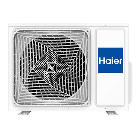
DC Inverter FREE MATCH J-Series
Model No.2U50S2SM1FA-3
WARNING
This service information is designed for experienced repair technicians only and is not designed for use by the general public.
It does not contain warnings or cautions to advise non-technical individuals of potential dangers in attempting to service a product.
Products powered by electricity should be serviced or repaired only by experienced professional technicians. Any attempt to service or
Repair the product or products dealt with in this service information by anyone else could result in serious injury or death
Version V1
Date 2021-05-31
Advertisement
Table of Contents

Related Manuals for Haier J Series


Summary of Contents for Haier J Series
- Page 1 SERVICE MANAUL Wall Mounted Type DC Inverter FREE MATCH J-Series Model No.2U50S2SM1FA-3 WARNING This service information is designed for experienced repair technicians only and is not designed for use by the general public. It does not contain warnings or cautions to advise non-technical individuals of potential dangers in attempting to service a product. Products powered by electricity should be serviced or repaired only by experienced professional technicians.
-
Page 2: Table Of Contents
Contents Contents 1. Introduction .................... 1 2. Specifications ..................7 3. Sensors list .................... 8 4. Piping diagrams ..................9 5. Operation range ..................10 6. Printed Circuit Board Connector Wiring Diagram ......... 11 7. Functions and Control ................8. Dimensional drawings ................9. -
Page 3: Introduction
Introduction 1 Introduction 1.1 Model name explanation Version Apply toT1; 220~240V50HZ/1ph Heat pump & R32 refrigerant Version 1 Platform of outdoor units: NEW1.5P The second generation Supermatch Nominal cooling capacity (18000BTU/h) Type of outdoor unit : U (normal type) The maximum combination number Domestic air conditioner... - Page 4 Introduction 1.2 Safety Cautions Be sure to read the following safety cautions before conducting repair work. The caution items are classified into “Warning” and “Caution”. The “Warning” items are especially important since they can lead to death or serious injury if they are not followed closely. The “Caution” items can also lead to serious accidents under some conditions if they are not followed.
- Page 5 Introduction Warning Do not repair the electrical components with wet hands . Working on the equipment with wet hands can cause an electrical shock Do not clean the air conditioner by splashing water. Washing the unit with water can cause an electrical shock.
- Page 6 Introduction Warning Be sure to use an exclusive power circuit for the equipment, and follow the technical standards related to the electrical equipment, the internal wiring regulations and the instruction manual for installation when conducting electrical work. Insufficient power circuit capacity and improper electrical work can cause an electrical shock or fire. Be sure to use the specified cable to connect between the indoor and outdoor units.
- Page 7 Introduction Do not install the equipment in a place where there is a possibility of combustible gas leaks. If a combustible gas leaks and remains around the unit, it can cause a fire. Be sure to install the packing and seal on the installation frame properly. If the packing and seal are not installed properly, water can enter the room and wet the furniture and floor.
- Page 8 Introduction Check the grounding, and repair it if the equipment is not properly grounded. Improper grounding can cause an electrical shock. Be sure to measure the insulation resistance after the repair, and make sure that the resistance is 1 M ohm or higher.
-
Page 9: Specifications
Specification 2 Specifications NOMINAL DISTRIBUTION SYSTEM VOLTAGE 220-240 NOMINAL CAPACITY and NOMINAL INPUT 12+12 n i l Capacity rated Btu/h 17064(4430-20470) 17740(6140-22520) Power Consumption(Rated) 1.45 Annual energy consumption 1645 ³ 12 single:2×10 TECHNICAL SPECIFICATIONS-UNIT Dimensions H*W*D 550×800×280 Packaged H*W*D 590×939×394 Dimensions Sound level ELECTRICAL SPECIFICATIONS... -
Page 10: Sensors List
Specification TECHNICAL SPECIFICATIONS-OTHERS Refrigerant type Refrigerant charge Refrigerant Maximum allowable distance 30(double) 20(single) circuit between indoor and outdoor Maximum allowable level difference Refrigerant control liquid 6.35 Piping connections 9.52 (external diameter) drain Heat insulation type Both liquid and Gas pipes Max. -
Page 11: Piping Diagrams
Pinping diagrams 4 Pinping diagrams Domes t ic air condi t ioner... -
Page 12: Operation Range
Operation range 5 Operation range Domestic air conditioner... -
Page 13: Printed Circuit Board Connector Wiring Diagram
Wiring diagram 6. Printed Circuit Board Connector Wiring Diagram Connectors PCB (1) Control PCB Connector for power N and L Connector for ground Connector for CN2,CN1 on the module board CN 8 CN10 Connector for four way valve coil CN17 Connector for electric expansion valves CN16 CN18... - Page 14 Wiring diagram PCB (2) Module PCB P (CN8) Connector for CN26,CN24 on the control board N (CN9) LO (CN4) Connector for reactor LI (CN3) AC_L(CN1) Connector for CN8,CN9 on the control board AC_N(CN2) CN5(U) Connector for the compressor CN6(V) CN7(W) CN10 Connector for the DC power 5V and 15V form the control PCB Connector for communicate between the control board and the module...
- Page 15 wiring diagram PCB (1) Domestic air conditioner...
- Page 16 wiring diagram PCB(2) Domestic air conditioner...
- Page 17 Wiring diagram OUTDOOR WIRING DIAGRAM 0011506856 Compressor Condensor R(U) C(W) S(V) CN26 CN38 CN29 CN24 RJ45 DRAM AC-L AC-N 2U18: AC-L OUT MOUDLE 2U14: CN23 AC-N OUT CN11 MOUDLE CN22 COM B POWER CN10 COM A MOUDLE PCB OUTDOOR PCB CN11 CN12 AC-L OUT...
-
Page 18: Functions And Control
Functions and control 7.Functions and Control 7.1 The control system of outdoor unit 7.1.1 The operation frequency of outdoor unit and its control 7.1.1.1 The operation frequency control of compresso r The operation frequency scope of compressor Mode Minimun operation frequency Maximun operation frequency 7.1.1.2 The starting of compressor When the compressor is started for the first time, it must be kept under the conditions of... - Page 19 Functions and control Refrigeration/dehumidification mode:: Serial No. Temperature scope Frequency limitation Wh_c<16 Max_hz1 37 HZ Wh_c<23 Max_hz2 45 HZ Wh_c<29 Max_hz3 56 HZ Wh_c<32 Max_hz4 63 HZ Wh_c<40 Max_hz5 90 HZ Wh_c<48 Max_hz4 90 HZ Wh_c>48 Max_hz5 90 HZ Remarks: the above are not only the maximum frequency limitations of the complete appliance which are affected by the environment, but also the maximum ability limitation of the system.
- Page 20 Functions and control When the outdoor unit is shut down, the valve is opened completely for 2 minutes, and then begin initialization. The scope of refrigerationg valve 90-----480 steps The scope of heating valve 70-----480 steps The valves are adjusted according to the degree of superheat SHa.
- Page 21 Functions and control Fgh_t1 Decreasing the frequency rapidly Fgh_t2 58℃ Fgh_t2 Fgh_t3 Fgh_t3 Fgh_t4 Fgh_t4 Fgh_t5 2 Normal N Decreasing at the speed of 1HZ/1 second P Decreasing at the speed of 1Hz/10 seconds Q Continue to keep the last-time instruction cycle R Increasing at the speed of 1Hz/10seconds Remarks: the outdoor unit 7.1.3.3...
- Page 22 Functions and control 7.1.3.5 Antifreezing protection of the indoor heat exchanger When refrigerating/heating, prevent freezing. Tpg_indoor is the minimum value of the effective indoor unit (start it and it is in accord with the running state). 11 //ice_temp_3+5 8 //ice_temp_3+2 Keeping the frequency ice_temp_3 ice_temp_2...
- Page 23 Functions and control 7.1.4.1 The ou tdoor fan control when refrigerating or dehumidifying In 3 minutes, the outdoor fan is After the compressor is started for 5 seconds, started according to the temperature conditions of the outdoor environment. Twh(℃) Twh <23℃ 23℃<Twh<29℃...
- Page 24 Functions and control 7.1.5 The control of the outdoor electronic expansion valve When starting the compressor: the opening size of the valve must be guaranteed to have entered into the standard opening size, and then the compressor can be started. When refrigeration is in vain (the machine is shut down or is in the state of retrograde operation), the opening size of the expansion valve of the indoor unit is 5 steps;...
- Page 25 Functions and control 7.2 Value of thermistor outdoor Unit Ambient Sensor, Defrosting Sensor, Pipe sensor R25 =10K 3% B25 /50 =3700K 3% Temp.( ) Max.(K ) Normal(K ) Min.(K ) Tolerance( ) 165.2170 147.9497 132.3678 -1.94 1.75 155.5754 139.5600 125.0806 -1.93 1.74 146.5609...
- Page 26 Functions and control 37.4465 35.0144 32.7108 -1.41 1.33 35.6202 33.3552 31.2062 -1.38 1.31 33.8936 31.7844 29.7796 -1.36 1.29 32.2608 30.2968 28.4267 -1.34 1.28 30.7162 28.8875 27.1431 -1.32 1.26 29.2545 27.5519 25.9250 -1.29 1.24 27.8708 26.2858 24.7686 -1.27 1.22 26.5605 25.0851 23.6704 -1.25 1.20...
- Page 27 Functions and control 5.3916 5.1308 4.8783 -1.37 1.33 5.2001 4.9430 4.6944 -1.41 1.36 5.0163 4.7630 4.5185 -1.45 1.40 4.8400 4.5905 4.3500 -1.49 1.44 4.6708 4.4252 4.1887 -1.53 1.47 4.5083 4.2666 4.0342 -1.57 1.51 4.3524 4.1145 3.8862 -1.61 1.55 4.2026 3.9686 3.7443 -1.65 1.59...
- Page 28 Functions and control 1.2583 1.1448 1.0405 -3.43 3.15 1.2226 1.1113 1.0092 -3.48 3.19 1.1880 1.0789 0.9789 -3.53 3.24 1.1546 1.0476 0.9497 -3.58 3.28 1.1223 1.0174 0.9215 -3.64 3.33 1.0910 0.9882 0.8942 -3.69 3.37 1.0607 0.9599 0.8679 -3.74 3.42 1.0314 0.9326 0.8424 -3.80 3.46...
- Page 29 Functions and control 9687.0270 8074.3787 6724.1389 -2.88 2.41 9057.2314 7564.2244 6311.6413 -2.87 2.41 8472.2852 7089.4741 5927.0206 -2.86 2.40 7928.7217 6647.4547 5568.2222 -2.84 2.39 7423.3626 6235.7109 5233.3554 -2.83 2.39 6953.2930 5851.9864 4920.6791 -2.82 2.38 6515.8375 5494.2064 4628.5894 -2.80 2.37 6108.5393 5160.4621 4355.6078 -2.79 2.37...
- Page 30 Functions and control 691.3524 622.3161 559.6694 -2.16 1.96 656.8979 592.1831 533.3634 -2.14 1.95 624.3328 563.6604 508.4261 -2.12 1.93 593.5446 536.6540 484.7796 -2.10 1.92 564.4275 511.0760 462.3510 -2.09 1.90 536.9865 486.9352 441.1516 -2.07 1.89 511.0105 464.0500 421.0258 -2.05 1.87 486.4151 442.3499 401.9146 -2.03 1.86...
- Page 31 Functions and control 89.0211 85.0614 81.2048 -1.18 1.15 85.4976 81.7908 78.1744 -1.15 1.12 82.1303 78.6615 75.2715 -1.13 1.10 78.9116 75.6668 72.4902 -1.10 1.08 75.8343 72.8004 69.8249 -1.08 1.06 72.8916 70.0561 67.2703 -1.05 1.03 70.0770 67.4283 64.8213 -1.03 1.01 67.3844 64.9115 62.4731 -1.00 0.99...
- Page 32 Functions and control 18.5157 17.4166 16.3680 -2.02 1.93 17.9590 16.8769 15.8458 -2.06 1.96 17.4214 16.3564 15.3427 -2.10 2.00 16.9023 15.8542 14.8577 -2.15 2.04 16.4010 15.3696 14.3902 -2.19 2.08 15.9167 14.9020 13.9394 -2.23 2.12 15.4489 14.4506 13.5047 -2.27 2.16 14.9968 14.0149 13.0855 -2.32 2.19...
-
Page 33: Dimensional Drawings
Dimensional drawing 8.Dimensional drawings 9.Center of gravity ● Domestic air conditioner... -
Page 34: Service Diagnosis
Service diagnosis 10Service Diagnosis 10.1 Caution for Diagnosis The operation lamp flashes when any of the following errors is detected. 1. When a protection device of the indoor or outdoor unit is activated or when the thermistor malfunctions, disabling equipment operation. 2. - Page 35 Service diagnosis 10.3 Problem Symptoms and Measures Symptom Check Item Details of Measure Check the power supply. Check to make sure that the rated voltage is supplied. None of the units operates Check the indoor PCB Check to make sure that the indoor PCB is broken Operation A power failure of 2 to 10 cycles can stop air conditioner Check the power supply.
- Page 36 Service diagnosis 10.3 Error Codes and Description indoor display Code indication Indoor displaying panel code indication Outdoor Reference fault description (LED1 Page Only For 498 and flash 498A display Other times) (Red/Green Time Run display Indoor and Communication fault between Page.42 Outdoor indoor and outdoor units...
- Page 37 Service diagnosis 10.4.1 Thermistor or Related Abnormality Indoor Display E1: Room temperature sensor failure E2: Heat-exchange sensor failure Outdoor display LED1 flash 10 times Defrost temperature sensor failure LED1 flash 11 times Suction temperature sensor failure LED1 flash 12 times Ambient temperature sensor failure LED1 flash 13 times Discharge temperature sensor failure Method of The temperatures detected by the thermistors are used to determine thermistor errors...
- Page 38 Service diagnosis 10.4.2 EEPROM abnormal Indoor Display E4: Indoor EEPROM error Indoor display F12: Outdoor EEPROM error; Outdoor LED1 flash 1 times Method of The Data detected by the EEPROM are used to determine MCU Malfunction Detection Malfunction When the data of EEPROM is error or the EEPROM is damaged Decision Conditions Supposed...
- Page 39 Service diagnosis 1 .4.3 Indoor DC fan motor fault Indoor display Method of DC fan motor is detected by checking the fan running condition and so on Malfunction Detection Malfunction when the detected rotation feedback signal don’t received in 2 minutes Decision Conditions Supposed...
- Page 40 Service diagnosis 10.4.3 Indoor AC fan motor malfunction Indoor Display Method of The rotation speed detected by the Hall IC during fan motor operation is used to determine Malfunction abnormal fan motor operation Detection Malfunction when the detected rotation feedback signal don’t received in 2 minutes Decision Conditions Supposed...
- Page 41 Service diagnosis 10.4.4 Outdoor DC fan motor fault Outdoor display LED1 flash 9 times Method of DC fan motor is detected by checking the fan running condition and so on Malfunction Detection when the detected rotation feedback signal don’t received in 2 minutes Malfunction Decision Conditions...
- Page 42 Service diagnosis 10.4.5 IPM protection Outdoor display: LED1 flash 2 times Method of IPM protection is detected by checking the compressor running condition and so on Malfunction Detection Malfunction The system leads to IPM protection due to over current Decision The compressor faulty leads to IPM protection Conditions circuit component of IPM is broken and led to IPM protection...
- Page 43 Service diagnosis 10.4.6 Over-current of the compressor Outdoor Display: LED1 flash 3 or 24 or 25 times Method of The current of the compressor is too high Malfunction Detection Malfunction when the IPM Module is damaged Decision or the compressor is damaged. Conditions power supply voltage is too low or too high Supposed...
- Page 44 Service diagnosis 10.4.7 The communication fault between IPM and outdoor PCB Outdoor display: LED1 flash 4 times Method of Communication is detected by checking the IPM module and the outdoor PCB Malfunction Detection Malfunction The outdoor PCB broken leads to communication fault Decision The IPM module broken leads to communication fault Conditions...
- Page 45 Service diagnosis 10.4.8 Power Supply Over or under voltage fault Outdoor display: LED1 flash 6 times The power supply is over voltage Method of An abnormal voltage rise or fall is detected by checking the specified voltage detection circuit. Malfunction Detection Malfunction An voltage signal is fed from the voltage detection circuit to the microcomputer...
- Page 46 Service diagnosis 10.4.9 Overheat Protection For Discharge Temperature Outdoor display: LED1 flash 8 times Method of The Discharge temperature control is checked with the temperature being detected Malfunction by the Discharge pipe thermistor Detection Malfunction when the compressor discharge temperature is above 116 Decision Conditions Supposed...
- Page 47 Service diagnosis 10.4.10 The communication fault between indoor and outdoor Indoor display outdoor display LED1 flash 15 times Method of Communication is detected by checking the indoor PCB and the outdoor PCB. Malfunction Detection Malfunction The outdoor PCB broken leads to communication fault. Decision The indoor PCB broken leads to communication fault.
- Page 48 Service diagnosis If the voltage is a constant value The indoor mainboard is of 0V DC to 5V DC.Or the voltage damaged; replace it with a between Communication line(red ) and N(white new one. line) is not close to18V DC when only indoor charged. Test the outdoor power is Check the cable supply 230VAC with a...
- Page 49 Service diagnosis 10.4.11 Loss of synchronism detection Inverter side current detection is abnormal Outdoor Display LED1 flash 18 times LED1 flash 19 times Method of The position of the compressor rotor can not detected normally Malfunction Detection Malfunction when the wiring of compressor is wrong or the connection is poor; Decision or the compressor is damaged Conditions...
-
Page 50: Performance And Cerves Diagrams
Service diagnosis 10.4.12 High work-intense protection Outdoor display LED1 flash 21 times Method of High work-intense control is activated in the heating mode if the temperature Malfunction being sensed by the heat exchanger thermistor exceeds the limit. Detection Malfunction Activated when the temperature being sensed by the heat exchanger Decision rises above 65 Conditions... - Page 51 Performance curves diagram Performance Curves Diagram 11.1 cooling capacity-temp. curves (12+12)performancecurves cooling value-temerature table outdoor tem p.(hum idity 46% ) indoo r tem p. D B /W B 3121 3089 4142 3710 4339 4232 3911 2750 18/12 3187 3154 4228 3797 4607 4339...
- Page 52 Performance curves diagram 11.2 heating capacity-temp.curves (12+12)performancecurves heating capacity and indoor/outdoor temp.table indoo r tem p.(hum idity 46% ) outdoor tem p. D B /W B heating capacity and indoor/outdoor temp.curves Domestic air conditioner...
- Page 53 Performance curves diagram 11.3 Coolingpower consumption-temp.curves (12+12)performancecurves power consumption value-temp.table outdoor tem p.(hum idity 46% ) indoo r tem p. D B /W B 1494 1594 1502 18/12 1519 1627 1668 18/14 20/15 1544 1652 1710 1001 1569 1668 1743 22/16 1023 1619...
- Page 54 Performance curves diagram 11.4 heating power consumption-temp.curves (12+12)performancecurves power consumption value-temp.table in d o o r te m p .(h u m id ity 4 6 % ) o u td o o r te m p . D B /W B -1 5 1 3 8 8 1 4 9 5...
- Page 55 Performance curves diagram 11.5 Cooling discharge pressure (12+12)performancecurves cooling discharge pressure.table outdoor tem p. indoo r tem p. (hum idity 46% ) D B /W B 1562 1616 1670 2331 2355 2403 2331 2379 2403 3248 3314 3414 3281 3447 3447 2154 2154...
- Page 56 Performance curves diagram 11.6 cooling suction pressure curves performance curves ( 12+12) cooling suction pressure.table outdoor tem p. indoo r tem p. (hum idity 46% ) D B /W B Domestic air conditioner...
- Page 57 Performance curves diagram 11.7 heating discharge pressure curves (12+12)performancecurves Heating discharge pressure.table outdoor tem p. indoo r tem p. (hum idity 46% ) D B /W B 3003 3133 3231 3068 3166 3264 3117 3198 3296 3166 3231 3329 3231 3264 3362 2957...
- Page 58 Performance curves diagram 11.8 heating suction pressure curves (12+12)performancecurves heating discharge pressure.table outdoor tem p. indoo r tem p. (hum idity 46% ) D B /W B 1000 O utdoor T em p Domestic air conditioner...
-
Page 59: Sound Level
Sound level 12 Sound level Sound presure level 230V,50Hz sound power level Measuring location Model Cooling/heating (cooling/heating) Location of microphone AARIA MULTI 250 P cooling heating 1700 3400 6800 1700 3400 6800 NC-70 NC-70 NC-60 NC-60 NC-50 NC-50 NC-40 NC-40 NC-30 NC-30 NC-20... - Page 60 Circuit diagrams 13 Circuit diagrams 13.1 Outdoor unit control board Circuit Diagrams 4.7K 0.1uF R100 4.7K 10K-0805 4.7K 1-6-MODE 100Ω -0805 0.1uF 1-18-DEBUG-RX1 100Ω -0805 100Ω -0805 1-20-DEBUG-TX1 STEPA1 R101 GT24C1024 1-9-RST 100Ω -0805 R102 EEPROM STEPD TJC-06 TJC-04 在线烧写 560-0805 1-28-EESCL CN30...
- Page 61 Circuit diagrams 13 Circuit diagrams 13.1 Outdoor unit control board Circuit Diagrams Domestic air conditioner...
- Page 62 Circuit diagrams 13.2 Module board Circuit Diagram Domestic air conditioner...
- Page 63 Sincere Forever Domestic air conditioner...
- Page 64 Wall Mounted Type DC Inverter FREE MATCH N-Series Model No.2U50S2SM1FA-3...
- Page 65 Remove of front panel Outdoor unit Loosen the service Be careful not to cover screw and cut your finger by remove the service the fins of the cover. heat exchanger...
- Page 66 Step Procedure Step Procedure Points Step Procedure Points Points 2. Remove the panels. Loosen the 7 screws and lift the top panel Loosen the screws of the panel. Pull and remove the front panel. Domestic air conditioner...
-
Page 67: Circuit Diagrams
Remove the fixting screws, then lift the electrical box Domestic air conditioner... - Page 68 Remove the air filters and horizontal flap Loosen the fixting screws and remove back protect net . ■ Loosen the fixting screws and remove the side panel. Domestic air conditioner...
- Page 69 Remove the casing Loosen the fixting screws and remove the side panel. ■ Loosen the fixting screws and remove the cross beam. Domestic air conditioner...
- Page 70 Loosen the fixting screws remove the fan Loosen the fixting screws and lift the fan motor. Domestic air conditioner...
- Page 71 Release stepping motor (2type) Remove fixing screws,then lift the fan motor bracket Cut down and pull out compressor and remove Domestic air conditioner...
- Page 72 Removal of Heat Exchanger Loosen the marked fixing screws Loosen the fixting hook Domestic air conditioner...
- Page 73 Remove fixing screw,then lift valve set Domestic air conditioner...