Table of Contents
Troubleshooting

Related Manuals for Daihen OTC WB-P400


Summary of Contents for Daihen OTC WB-P400
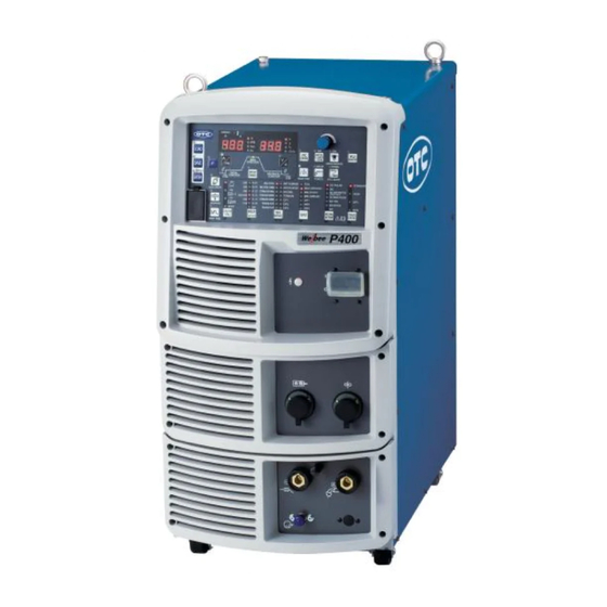
- Page 1 Pulsed MAG/MIG Welding power source P400 Welbee Inverter OWNER'S MANUAL Model: WB-P400 Ensure to read this instruction manual thoroughly for safe and proper use of the product. March, 2017 Manual No. : P30194-2 DAIHEN Corporation...
-
Page 3: Forward
Preliminaries Forward Thank you for your purchase of OTC's welding power source. This Owner's Manual (hereafter referred to as "this manual") explains the following points for safe use of the product. • Caution regarding the product • Welding operation/setting method •... -
Page 4: Important Information
Important Information Use of the Product This product is a power supply unit designed and manufactured for use in arc welding. Do not use the product for any other purposes. Safe Use of the Product For safe use of the product (hereafter referred to as welding power source), ensure to follow the instructions below: •... -
Page 5: Service And Support
Service and Support See the back cover for contact numbers and mailing addresses. When contacting your dealer for service, you are required to provide the following information: • Name, address, telephone number • Product model, manufacture year, serial number, and software version number (Refer to the diagram below for product information. -
Page 6: Table Of Contents
ABLE OF ONTENTS TABLE OF CONTENTS CHAPTER 4 CONNECTION Forward ........i Important Information. - Page 7 ABLE OF ONTENTS CHAPTER 10REFERENCE MATERIALS 6.5.1 Memory registration of welding conditions. . . 6-10 6.5.2 Read out of welding conditions ... 6-11 10.1 Parts List ......10-1 6.5.3 Deletion of memory registration .
- Page 8 ABLE OF ONTENTS (MEMO)
-
Page 9: Chapter 1 Safety Information
Chapter 1 Safety Information This chapter explains the precautions on the welding power source and welding operation. 1.1 Warning Symbols The following safety warning symbols and signs are used throughout the manual to ensure proper operation of the product and to prevent from various hazards that cause serious injury and damages. Indication and explanation for the symbols are as follows: Make sure to fully understand the content before beginning operation. -
Page 10: Operating Precautions
HAPTER AFETY NFORMATION AFETY RECAUTION 1.2.1 Operating precautions To prevent serious injury or accidents, ensure to follow the instructions below: • Be sure to read and understand the information in the manual before operating the product. Have only trained and experienced personnel perform operation of welding power source or welding machine. -
Page 11: Precautions For Power Supply And Electric Shock
HAPTER AFETY NFORMATION AFETY RECAUTION 1.2.2 Precautions for power supply and electric shock To prevent electric shock or burn injury, ensure to follow the instructions below: • Do not touch the input and output terminals and the internal live electrical parts of the welding power source. -
Page 12: Precautions For Air Discharge And Use Of Respiratory Protective Equipment
HAPTER AFETY NFORMATION AFETY RECAUTION 1.2.3 Precautions for air discharge and use of respiratory protective equipment To prevent suffocation or gas poisoning in the welding operation, ensure to follow the instructions below: • When welding is required in tank, boiler, reaction tower, or hold of a ship, closed space, or any other places of poor ventilation, ensure to provide ventilation equipment. -
Page 13: Precautions For Flammable Materials
HAPTER AFETY NFORMATION AFETY RECAUTION 1.2.4 Precautions for flammable materials To prevent fire, explosion and rupture, ensure to follow the instructions below: • Remove all flammables within 10 m (33 ft) of the welding arc so that sparks and spatter do not strike flammable materials. If this is not possible, tightly cover them with noncombustible covers. -
Page 14: Precautions For Gas Cylinder And Gas Regulator
HAPTER AFETY NFORMATION AFETY RECAUTION 1.2.5 Precautions for gas cylinder and gas regulator To prevent falling of gas cylinder, gas regulator explosion and accident caused by gas, ensure to follow the instructions below: • Use only correct shield gas cylinders according to the related laws, regulations and customer's standard. -
Page 15: Precautions For Disassembling And Modifying The Welding Power Source
HAPTER AFETY NFORMATION AFETY RECAUTION 1.2.7 Precautions for disassembling and modifying the welding power source To prevent electrical shock, fire, injury from malfunction and error in the welding power source, ensure to follow the precautions below: • Do not disassemble/modify the welding power source. Disassembling/modifying by customer is out of the warranty scope. -
Page 16: Principal Safety Standards
HAPTER AFETY NFORMATION RINCIPAL AFETY TANDARDS 1.3 Principal Safety Standards Arc welding equipment – Installation and use, Technical Specification IEC 62081, from International Electro technical Commission Arc welding equipment Part 1: Welding power sources IEC 60974-1, from International Electro technical Commission Safety in Welding and Cutting, ANSI Standard Z49.1, from American Welding Society. -
Page 17: Chapter 2 Product Specification And Configuration
Chapter 2 Product Specification and Configuration This chapter explains the specification, name of each parts and configuration of the welding power source. 2.1 Specification This section explains the specification and external dimension of the welding power source. 2.1.1 Specifications This section explains the specification of the welding power source. Specification/Model Welbee Inverter P400 Model... - Page 18 HAPTER RODUCT PECIFICATION AND ONFIGURATION PECIFICATION Specification/Model Welbee Inverter P400 Model WB-P400 Number of phase Single phase Rated frequency 50/60 Hz Rated input voltage 208/230 V 460 V Input voltage range 208/230 V ± 10 % 460 V ± 10 % DC:11.2 kVA, 9.4 kW DC:13.8 kVA, 9.3 kW Rated input...
-
Page 19: Applicable Welding Method
HAPTER RODUCT PECIFICATION AND ONFIGURATION PECIFICATION 2.1.2 Applicable welding method This section explains the applicable welding method (shield gas/wire type/welding type) and wire diameter. Standard specification WELDING Penetration GAS (*1) WIRE MATERIALS WIRE DIA. [in. (mm)] TRAVEL SPEED METHOD adjustment 030 / .035 / .040 /.045 MILD STEEL (*2) (*3) -
Page 20: External Dimensions
HAPTER RODUCT PECIFICATION AND ONFIGURATION PECIFICATION 2.1.3 External dimensions This section explains the external dimensions of the welding power source. 15.6" (395 mm) 28.0" (710 mm) 12.6" (320 mm) 18.1" (460 mm) 3.9" (100 mm) -
Page 21: Rated Duty Cycle
HAPTER RODUCT PECIFICATION AND ONFIGURATION PECIFICATION 2.1.4 Rated duty cycle This section explains the rated duty cycle of the welding power source. • Use this welding power source at or under the rated duty cycle. Exceeding the rated duty cycle may result in deterioration and damage to the welding power source. -
Page 22: Product Configuration
HAPTER RODUCT PECIFICATION AND ONFIGURATION RODUCT ONFIGURATION 2.2 Product Configuration This section explains the standard or optional composition of the welding power source and parts to be prepared by customers. 2.2.1 Standard composition This section explains the standard composition of the welding power source. For equipment used in combination with the welding power source connected to robot, refer to the instruction manual of the robot controller. - Page 23 HAPTER RODUCT PECIFICATION AND ONFIGURATION RODUCT ONFIGURATION *1: Optional extension cable and hose [196.9" /393.7" /590.6" /787.4" (5 m/10 m/15 m/20 m)] are also available. 2.2.4 Optional accessories) • At TIG welding: Welding power source Base metal Required Optional Name Remarks component accessories...
-
Page 24: Accessory (Supplied)
HAPTER RODUCT PECIFICATION AND ONFIGURATION RODUCT ONFIGURATION • At DC STICK welding: Welding power source Base metal Required Optional Name Remarks component accessories To be prepared by the customer. Welding electrode holder 2.2.3 Accessory (not supplied)) ○ Power cable [AWG2 (38mm ) or more] (*1) ○... -
Page 25: Accessory (Not Supplied)
HAPTER RODUCT PECIFICATION AND ONFIGURATION RODUCT ONFIGURATION 2.2.3 Accessory (not supplied) This section explains the accessories to be prepared by the customer before operating the welding power source. Prepare the following: • Shield gas Use a shield gas suitable to the welding method. Name Remarks Carbon dioxide (CO... - Page 26 HAPTER RODUCT PECIFICATION AND ONFIGURATION RODUCT ONFIGURATION 2.2.4.2 Details on extension cables and hoses Following extension cables and hoses are optionally available. For extending the working radius, use extension cable and hose according to the working radius. • When using extension cables, roll them out. Winded extension cable may cause an unstable arc.
-
Page 27: Part Names
HAPTER RODUCT PECIFICATION AND ONFIGURATION AMES 2.3 Part Names This section explains the part names of the welding power source. 2.3.1 Front panel The section explains the front section of the welding power source. Operation panel 6.2 Function on Operation Panel) Main power lamp Power switch Socket for wire feeder... -
Page 28: Rear Panel
HAPTER RODUCT PECIFICATION AND ONFIGURATION AMES 2.3.2 Rear panel The section explains the rear section of the welding power source. Print circuit board Connector for connecting CAN Terminal block for Blind bush Cover for external external connections (for drawing externally connections 4.5.2 Connection of connecting wire) -
Page 29: Chapter 3 Transportation And Installation
Chapter 3 Transportation and Installation This chapter explains the necessary equipment, installation environment and transportation method for installing the welding power source. 3.1 Required Equipment This section explains the necessary power supply equipment for installing the welding power source and equipment for preventing lack of oxygen and dust hazard during welding. -
Page 30: Ventilation Equipment/Partial Exhaust Facility
HAPTER RANSPORTATION AND NSTALLATION EQUIRED QUIPMENT When using an engine generator for the welding power source, pay attention to the following. • Set the output voltage of the engine generator to the voltage range between 230 or 460 V at no-load welding operation. -
Page 31: Installation Environment
HAPTER RANSPORTATION AND NSTALLATION NSTALLATION NVIRONMENT 3.2 Installation Environment This section explains the installation environment of the welding power source. • For prevention from fire or damage to the welding power source, be sure to install in a location that satisfies the following environment: 3.2.1 Installation environment •... -
Page 32: Transportation Procedure
HAPTER RANSPORTATION AND NSTALLATION RANSPORTATION ROCEDURE 3.3 Transportation Procedure This section explains the procedure for transportation of the welding power source. • Do not touch the input and output terminals and the internal live electrical parts of the welding power source. It may cause electric shock. -
Page 33: Transportation With Lifting Lug
HAPTER RANSPORTATION AND NSTALLATION RANSPORTATION ROCEDURE 3.3.1 Transportation with lifting lug This section explains the procedure for transportation with lifting lug such as a crane. For preventing falling of the welding power source and resulting accidents, be sure to observe the following: •... -
Page 34: Manual Transportation With Carts
HAPTER RANSPORTATION AND NSTALLATION RANSPORTATION ROCEDURE 3.3.2 Manual transportation with carts This section explains the manual procedure for transportation using equipment such as a cart. • When lifting the welding power source, make sure to hold the bottom of the welding power source by more than one person. -
Page 35: Chapter 4 Connection
Chapter 4 Connection This chapter explains the procedure for connecting the welding power source. 4.1 Precautions for Connection Procedure and Grounding This section explains the precaution for connection and grounding procedure. For protection from serious injury or fire, observe the following: For protection from electric shock, observe the following points: •... -
Page 36: Connecting The Welding Power Source
HAPTER ONNECTION ONNECTING THE ELDING OWER OURCE 4.2 Connecting the Welding Power Source This section explains the procedure for connecting the welding power source. Follow the steps below for connection of the welding power source. • Do not turn on the input power of the welding power source until confirming the completion of connection work. -
Page 37: Connection Of Cable At Output Side
HAPTER ONNECTION ONNECTING THE ELDING OWER OURCE 4.2.1 Connection of cable at output side This section explains the procedure for connecting of cable at output side. • Use a grounding cable for the case, of welding power source and perform grounding. Otherwise, voltage may increase in the case or base metal which could cause electric shock. -
Page 38: Connection Of Wire Feeder
HAPTER ONNECTION ONNECTING THE ELDING OWER OURCE 4.2.2 Connection of wire feeder This section explains the connecting procedure of the wire feeder. Refer also to the instruction manual of wire feeder. • When not using an analog remote control (optional accessory), do not remove the cap for the analog remote control. -
Page 39: Connection Of Welding Torch
HAPTER ONNECTION ONNECTING THE ELDING OWER OURCE 4.2.3 Connection of welding torch This section explains the procedure for connecting the welding torch. When air-cooled welding torch is used Wire feeder Power cable for torch side When water-cooled welding torch is used Condensing water port (red collar) Feeding water port... -
Page 40: Connection At Tig Welding
HAPTER ONNECTION ONNECTING THE ELDING OWER OURCE 4.2.4 Connection at TIG welding • In using the welding power source for TIG welding, prepare a welding torch by the customer. • Contrary to the normal connection, the TIG welding requires connection of the welding torch to the output terminal (base metal side). -
Page 41: Connection At Dc Stick Welding
HAPTER ONNECTION ONNECTING THE ELDING OWER OURCE 4.2.5 Connection at DC STICK welding • In using the welding power source for DC STICK welding, prepare a welding electrode holder by the customer. • After five seconds have passed, the safety voltage(approx.15 V) is automatically provided. -
Page 42: Connection Of Shield Gas
HAPTER ONNECTION ONNECTING THE ELDING OWER OURCE 4.2.6 Connection of shield gas This section explains the procedure for connecting the shield gas. Refer also to the instruction manual of wire feeder. • Be sure to observe the following points to prevent from suffocation due to gas leakage or explosion. -
Page 43: Grounding And Connection Of Input Power Supply
HAPTER ONNECTION ROUNDING AND ONNECTION OF NPUT OWER UPPLY 4.3 Grounding and Connection of Input Power Supply This section explains the procedure for performing grounding work, connecting the welding power source and input power supply (power supply at facility side). •... -
Page 44: Confirmation Of Connection
HAPTER ONNECTION ONFIRMATION OF ONNECTION Connect the power cables (3 pcs) to the output terminals of power source at facility side. Input cable : AWG6 (13.3 mm ) with 0.4" (10 mm ) terminal × 3 ● Grounding and connection of input power supply is complete. Procedure is followed by 4.4 Confirmation of Connection. - Page 45 HAPTER ONNECTION ONNECTION OF XTERNAL QUIPMENT 4.5.1.1 Configuration example for connection Gas shortage/wire shortage Pack wire detection circuit Gas cylinder Signal line (*1) Internal printed circuit board Case ground Robot controller Socket for Voltage detection terminal Control cable the wire for base metal side (17 core) Manipulator...
-
Page 46: Connection Of Automatic Machine
HAPTER ONNECTION ONNECTION OF XTERNAL QUIPMENT 4.5.2 Connection of automatic machine This section explains the procedure for connection of automatic machine with the welding power source. 4.5.2.1 Wiring for connecting automatic machine The welding power source is equipped with terminal block for external connection inside the cover for external connection at the rear. - Page 47 HAPTER ONNECTION ONNECTION OF XTERNAL QUIPMENT • Output signal of the external connection terminal block Welding power Output signal is open collector output. Ensure to keep the source side maximum rated power of the transistor. Maximum rated power of transistor READY: DC50 V/100 mA OUT EXT1 to 4: DC50 V/100 mA Transistor...
- Page 48 HAPTER ONNECTION ONNECTION OF XTERNAL QUIPMENT Cover for external connections Attaching screw Cable (vinyl) Strip the cable cover by 25/64 to 7/16" (10 to 11 mm) Blind bush Button Terminal block Attaching screw Check that input power is turned off with the disconnect switch connected to the welding power source.
-
Page 49: Wiring Of Voltage Detection Cable At Base Metal Side
HAPTER ONNECTION IRING OF OLTAGE ETECTION ABLE AT ETAL 4.6 Wiring of Voltage Detection Cable at Base Metal Side When the extension cable is 118.1" (30 m) or more in length in total, use of the voltage detection cable at the base metal side is recommended. -
Page 50: Wiring To Welding Power Source
HAPTER ONNECTION IRING OF OLTAGE ETECTION ABLE AT ETAL Restore the right side panel of the wire feeder. Wiring of voltage detection cable is complete. 4.6.2 Wiring to welding power source This section explains how to connect the voltage detection cable at the base metal side to the voltage direct detection terminal at the base metal side of the welding power source. -
Page 51: Wiring Example Of Voltage Detection Cable
HAPTER ONNECTION IRING OF OLTAGE ETECTION ABLE AT ETAL 4.6.3 Wiring example of voltage detection cable This section shows the wiring examples of the voltage detection cables at the base metal side to the base metal. 4.6.3.1 Wiring examples for plural welding stages Connect the voltage detection cable at the base metal side to the stage to which the cable on the base metal side was last connected. - Page 52 HAPTER ONNECTION IRING OF OLTAGE ETECTION ABLE AT ETAL 4-18...
-
Page 53: Chapter 5 Welding Operation
Chapter 5 Welding Operation This chapter explains the procedures from preparation to completion of the welding operation. 5.1 Precaution at Welding Operation This section explains the safety precautions for welding operation. 5.1.1 Precautions for air discharge and use of respiratory protective equipment To prevent suffocation or gas poisoning in the welding operation, ensure to follow the instructions below:... -
Page 54: Precaution For Protective Equipment
HAPTER ELDING PERATION HECK BEFORE ELDING 5.1.2 Precaution for protective equipment For protection from arc ray generated from welding, spatter and spattering dross and hearing disorder from noise, observe the following: • Wear safety goggles with sufficient blocking effect or face shield in the work area and the surrounding. - Page 55 HAPTER ELDING PERATION HECK BEFORE ELDING Check parameter Countermeasures Check The voltage detection cables at the base metal side and the torch side The voltage detection cable should be should be wired along each other. adequately wired. Keep the voltage detection cable (base metal side) at least 3.9" (10 cm) away from the cable at the base metal side.
-
Page 56: Power On And Gas Supply
HAPTER ELDING PERATION OWER UPPLY Check parameter Countermeasures Check Ensure that the torch cable has no bending at a sharp angle. If the liner is clogged with dirt or when inched wire has flaw, replace the There should be no large feeding resistance liner with a new one. -
Page 57: Wire Inching
HAPTER ELDING PERATION NCHING Turn ON the power switch of the welding power supply. Check that the flow rate adjustment knob is set to "SHUT", and press the GAS CHECK key. The LED of the GAS CHECK key lights up, turning to the gas check status (shield gas is discharged). ⇒... -
Page 58: Check And Setting Of Welding Condition
HAPTER ELDING PERATION HECK AND ETTING OF ELDING ONDITION TIPS • Wire feeding is also enabled by a remote control (optional). Turning the welding current adjustment knob can adjust the feed speed. ( Operation of Analog Remote Control (Optional)) 5.5 Check and Setting of Welding Condition This section explains how to check the welding condition as well as how to prevent erroneous operation on the operation panel (Erroneous operation prevention function). -
Page 59: Performing Welding Operation
HAPTER ELDING PERATION ERFORMING ELDING PERATION 5.5.2.2 Deactivating erroneous operation prevention function Press and hold the ENTER key for approximately three seconds or more again. The LED of the ENTER key lights off, which deactivates the erroneous operation prevention function. ⇒... -
Page 60: Operation During Welding
HAPTER ELDING PERATION ERFORMING ELDING PERATION TIPS • The displayed average value is processed by the software. Note that the value cannot be guaranteed as the control data for a measurement instrument. 5.6.2 Operation during welding This section explains the operation requiring adjustment of welding current/voltage during the welding. - Page 61 HAPTER ELDING PERATION ERFORMING ELDING PERATION Press the DISPLAY CHANGE key. The displays on the left/right digital meters return to the display of current/voltage in welding. ⇒ TIPS • When no operation is performed for approximately 5 seconds, the display will return to the one showing current/voltage in welding.
-
Page 62: Operation At Welding End
HAPTER ELDING PERATION ERFORMING ELDING PERATION 5.6.3 Operation at welding end This section explains the supply stop procedure of power/shield gas after the welding end. Main valve GAS CHECK key Flow rate Welding power adjustment knob GAS CHECK source SHUT Shut off Power switch Welding power... -
Page 63: Chapter 6 Welding Condition
Chapter 6 Welding Condition This chapter explains the functions on the operation panel as well as how to set the welding conditions. 6.1 List of Welding Conditions This section explains the parameters/functions settable in the welding power source. 6.1.1 Parameter (Welding parameter) Set Range Initial Parameter... -
Page 64: Internal Function
HAPTER ELDING ONDITION IST OF ELDING ONDITIONS Function Initial value Setting parameter CONSTANT ON/OFF PENETRATION 6.1.3 Internal function Details of internal function ( 6.7 Setting Internal Functions) The functions with circle mark (O) on the Memory row can be stored with the welding conditions. Function Name Setting range Initial value... - Page 65 HAPTER ELDING ONDITION IST OF ELDING ONDITIONS Function Name Setting range Initial value Explanation Memory Allows fine tuning meltage of the wire at the end ○ Anti-stick voltage adjustment -9.9 to 9.9 0.0 (V) of welding based on the anti-stick process voltage.
- Page 66 HAPTER ELDING ONDITION IST OF ELDING ONDITIONS Function Name Setting range Initial value Explanation Memory Sets the initial condition and crater condition as applied for a fixed period of time regardless of the Special crater ○ OFF/ON torch switch operation: sequence OFF: Not applied ON: Applied (Time set by F46 and F47 is applied)
- Page 67 HAPTER ELDING ONDITION IST OF ELDING ONDITIONS Function Name Setting range Initial value Explanation Memory Arc loss detection time Arc start error detection time WCR output ON Used when connecting with OTC automatic OFF (fixed) delay time machine. WCR output OFF delay time Analog setting switch Pulse peak current fine...
-
Page 68: Function On Operation Panel
HAPTER ELDING ONDITION UNCTION ON PERATION ANEL 6.2 Function on Operation Panel This section explains the function of displays and keys arranged on the operation panel. WARNING IPM. sec. LOAD JOB No. INITIAL WELD CONDI MONITOR CONTROL -TION MAIN CONSTANT PENETRATION CONDITION IPM. - Page 69 HAPTER ELDING ONDITION UNCTION ON PERATION ANEL Name Function Select the TRAVEL SPEED to apply. (*1) • The LED of the parameter in selection lights up. TRAVEL SPEED key • Some option is invalid depending on the combination of the wire diameter, wire material, gas and the welding method.
-
Page 70: Welding Conditions
HAPTER ELDING ONDITION ELDING ONDITIONS Name Function Select air-cooled welding torch or water-cooled welding torch to be used. Switching the mode is enabled by pressing the key. TORCH key • When the LED is ON: water-cooled welding torch mode (*1) •... -
Page 71: Preparing Welding Conditions
HAPTER ELDING ONDITION REPARING ELDING ONDITIONS • Synergic adjustment of voltage ( 6.2 Function on Operation Panel) Using the VOLT.ADJUST key enables to automatically set the welding voltage according to the welding current. Fine adjustment of the welding voltage automatically set is also available. •... -
Page 72: Memory Registration Of Welding Conditions
HAPTER ELDING ONDITION EMORY UNCTION OF ELDING ONDITIONS • The welding conditions (electronic data) stored by this function are susceptible to occurrence of static electricity, impact, repair, etc., and there is a possibility that the stored contents may be changed or lost. BE SURE TO MAKE A COPY FOR IMPORTANT DATA. -
Page 73: Read Out Of Welding Conditions
HAPTER ELDING ONDITION EMORY UNCTION OF ELDING ONDITIONS Press the ENTER key. The LED of ENTER key flashes. ⇒ 3 sec. Pressing the DISPLAY CHANGE key enables to ⇒ ENTER check the value of welding parameter registered in the JOB No. to overwrite. The setting values are displayed on the left/right digital meters in a 3 sec. -
Page 74: Deletion Of Memory Registration
HAPTER ELDING ONDITION EMORY UNCTION OF ELDING ONDITIONS Press the ENTER key. The LED of ENTER key flashes. ⇒ 3 sec. Pressing the DISPLAY CHANGE key enables to ⇒ ENTER check the set values of welding conditions (welding parameters) to read out. The setting values are displayed on the left/right digital meters in a 3 sec. -
Page 75: Setting Welding Conditions
HAPTER ELDING ONDITION ETTING ELDING ONDITIONS Turn the parameter adjustment knob, and select the JOB No. to delete. To delete all the registration at the same time, turn ● the parameter adjustment knob counterclockwise, to display "ALL" on the right digital meter. When "ALL"... - Page 76 HAPTER ELDING ONDITION ETTING ELDING ONDITIONS WELDING Penetration GAS (*1) WIRE MATERIALS WIRE DIA. [in. (mm)] TRAVEL SPEED METHOD adjustment 030 / .035 / .040 /.045 MILD STEEL (*2) (*3) Enable (0.8/0.9/1.0/ 1.2) .030 / .035 / .040 /.045 MILD STEEL (*2) (*3) Enable (0.8/0.9/1.0/1.2)
- Page 77 HAPTER ELDING ONDITION ETTING ELDING ONDITIONS <Relationship of wire diameter and welding current at aluminum welding (Reference)> Wire diameter Range of stable welding Aluminum material Welding method [in. (mm) ] power source (A) 60 to 150 .040 (1.0) DC pulse/DC wave pulse 50 to 150 75 to 250 HARD ALUMINUM...
-
Page 78: Setting Welding Parameter
HAPTER ELDING ONDITION ETTING ELDING ONDITIONS 6.6.2 Setting welding parameter This section explains how to set the welding parameter (gas discharge time, welding current/voltage). The welding parameters are set according to the welding sequence. 6.6.2.1 Welding sequence The basic welding sequence is the process of PRE FLOW, MAIN CONDITION, and POST FLOW. To this sequence, initial condition and crater condition can be added depending on the crater setting. -
Page 79: Crater Setting
HAPTER ELDING ONDITION ETTING ELDING ONDITIONS Set the welding current. Press the DISPLAY CHANGE key, and select the LED of "MAIN CONDITION" (or "INITIAL ● CONDITION" or "CRATER-FILL CONDITION"). Check the lighting on the LED "A" (unit of welding current). When the LED is lights off, press the ●... - Page 80 HAPTER ELDING ONDITION ETTING ELDING ONDITIONS The pattern of the following combinations and can not be selected. Pattern No. Crater setting WELDING METHOD TRAVEL SPEED WIRE MATERIALS with pulse DC PULSE/ no pulse INCONEL DC WAVE PULSE DC PULSE/ MIG (100 % Ar) no pulse STAINLESS FERRITE DC WAVE PULSE...
- Page 81 HAPTER ELDING ONDITION ETTING ELDING ONDITIONS 6.6.3.1 Crater "OFF" Select "CRATER OFF" by the CRATER-FILL key. • In synchronous to the ON/OFF operation of the torch switch, the welding starts/stops. Torch switch Pre-flow Post-flow Gas flow No-load voltage Anti-stick time Output voltage Slow-down speed Wire feeding speed...
- Page 82 HAPTER ELDING ONDITION ETTING ELDING ONDITIONS 6.6.3.2 Crater "ON" (no initial condition) Select "CRATER-FILL ON (no pulse) " or "CRATER-FILL ON (with pulse)" by the CRATER-FILL key to light off the LED of the INITIAL CONDITION key. • Carry out twice the ON/OFF operation of the torch switch and carry out the welding operation. In the second ON operation, the welding sequence is carried out by the crater current.
- Page 83 HAPTER ELDING ONDITION ETTING ELDING ONDITIONS 6.6.3.3 Crater "ON" (with initial condition) Select "CRATER-FILL ON (no pulse) " or "CRATER-FILL ON (with pulse)" by the CRATER-FILL key to light on the LED of the INITIAL CONDITION key. • Carry out twice the ON/OFF operation of the torch switch and carry out the welding operation. The operation from the first ON to OFF enables the welding by the initial current, and the second ON operation enables the welding by the crater current.
-
Page 84: Arc Spot Time
HAPTER ELDING ONDITION ETTING ELDING ONDITIONS 6.6.4 Arc spot time This section explains the details of arc spot and torch switch operation. Selecting "ARC SPOT" by the CRATER-FILL key allows the machine in the main mode. • In this mode, the torch switch remains to be ON for welding operation. When the arc spot time elapses, the welding automatically stops. -
Page 85: Arc Characteristics Adjustment
HAPTER ELDING ONDITION ETTING ELDING ONDITIONS SYNERGIC mode ■ Press the VOLT.ADJUST key. When the LED of the key is ON, it means the SYNERGIC mode is applied. • The welding voltage is automatically set to the values corresponding to the welding current. •... -
Page 86: Adjustment Of Wave Frequency
HAPTER ELDING ONDITION ETTING ELDING ONDITIONS 6.6.8 Adjustment of wave frequency This section explains how to adjust the wave frequency. In wave pulse welding, cyclically accumulating two separate unit pulse conditions at low frequency enables to obtain continuous weld bead looking like rows of fish scales. - Page 87 HAPTER ELDING ONDITION ETTING ELDING ONDITIONS Select the welding sequence to adjust. Press the DISPLAY CHANGE key, and select either ● "INITIAL CONDITION", "MAIN CONDITION" or "CRATER-FILL CONDITION". DISPLAY CHANGE The LED for the selected welding sequence lights up. ⇒ MAIN CONDITION IPM.
-
Page 88: Setting Internal Functions
HAPTER ELDING ONDITION ETTING NTERNAL UNCTIONS 6.7 Setting Internal Functions This section explains how to set the internal functions with the details. The internal functions can be customized according to the using environment of the customer for further convenient use of the welding power source. 6.7.1 Setting procedure This section explains how to set the internal functions. -
Page 89: Detailed Information On Internal Functions
HAPTER ELDING ONDITION ETTING NTERNAL UNCTIONS Turn the parameter adjustment knob, and change the setting value. The set value is activated as it is changed. ⇒ Pressing the F (Function) key enables to return the ⇒ display to the status described in step 1. WARNING IPM. - Page 90 HAPTER ELDING ONDITION ETTING NTERNAL UNCTIONS Setting Parameter 5 (Automatic machine 3) 0 (Semi-automatic) 1 (Automatic machine 1) 2 (Automatic machine 2) (*6) After short-circuiting the pins [3]-[4] operation stop Cancellation of terminals on the Short-circuit the operation stop terminal pins [3]-[4] on the external connection operation stop external connection terminal block TM3.
- Page 91 HAPTER ELDING ONDITION ETTING NTERNAL UNCTIONS *5: For the applicable plug of analog remote control receptacles: See specification DPC25-6A/Part No. 4730-009. *6: If you want to use Automatic machine 3, conditions will change for the following functions. • F5 (Maximum external command voltage) : Fixed to "10.0V" •...
- Page 92 HAPTER ELDING ONDITION ETTING NTERNAL UNCTIONS 6.7.2.4 F6: Upslope time When the difference between the initial current and welding current is large, the wire may burn up at the change of the conditions. In this case, adjust the time period changing from the initial current to the welding current (upslope time) longer.
- Page 93 HAPTER ELDING ONDITION ETTING NTERNAL UNCTIONS 6.7.2.9 F11: Fine adjustment of welding conditions memory When the analog remote control (optionally available) is used, fine adjustment of the welding current and welding voltage of welding condition stored on the welding condition memory is available. This function is effective when the internal function F4 (Auto/Semi-auto mode) is set to "0".
- Page 94 HAPTER ELDING ONDITION ETTING NTERNAL UNCTIONS 6.7.2.11 F14/F15: Start control (time/current) adjustment Set the time and current for start control to be performed at the time of welding start. Depending on the welding conditions and set current value, the appropriate time and current for start control are determined;...
- Page 95 HAPTER ELDING ONDITION ETTING NTERNAL UNCTIONS • Adjust the anti-stick process voltage in the range of ± 9.9 V through the internal function F18. Based on "0," adjusting it to the negative values decreases the voltage, and adjusting it to the positive increases the voltage.
- Page 96 HAPTER ELDING ONDITION ETTING NTERNAL UNCTIONS 6.7.2.18 F23: Sleep mode switching time When the welding power source is not operated for a fixed period of time, it can be turned into the sleep mode. • [0]: disables the function. • [1] to [10]: enables the function. Set the transition time to the sleep mode in the range of 1 to 10.
- Page 97 HAPTER ELDING ONDITION ETTING NTERNAL UNCTIONS • [OFF]: disables the function. – The wire feed speed is automatically set based on the welding current. – Even when the welding mode is changed by the GAS key, the wire feed speed is automatically set based on the set welding current.
- Page 98 HAPTER ELDING ONDITION ETTING NTERNAL UNCTIONS 6.7.2.21 F29 to F32: External input terminal setting Set the function of external input terminals. (when using robot or automatic machines) • F29: set the function of IN-EXT1 ("5" to "9") on the external connection terminal block TM3. •...
- Page 99 HAPTER ELDING ONDITION ETTING NTERNAL UNCTIONS JOB No. Function (external input terminal) (Registration F29(IN-EXT1) F30(IN-EXT2) F31(IN-EXT3) F32(IN-EXT4) No.) OFF (open) ON (close) ON (close) ON (close) ON (close) ON (close) ON (close) ON (close) The external input terminal without the setting "5" is regarded as signal OFF. Accordingly, for the function (external input terminal) which does not require the "ON"...
- Page 100 HAPTER ELDING ONDITION ETTING NTERNAL UNCTIONS Do not change condition within 40 msec Switch IN-EXT1 and 3 More than 100 msec before before and 100 msec after torch within 40 msec. torch switch is turned on. switch is turned off. CLOSE -EXT1 OPEN...
- Page 101 HAPTER ELDING ONDITION ETTING NTERNAL UNCTIONS 6.7.2.22 F38: Arc voltage direct detection switching Sets the status of the voltage direct detection terminal on the base metal side of the welding power source or voltage detection terminal of the wire feeder. Extending the power cable without the cable at the base metal side can cause extraordinary volume of spatter.
- Page 102 HAPTER ELDING ONDITION ETTING NTERNAL UNCTIONS NOTE • Do not carelessly change the setting of this function. 6.7.2.25 F43: CAN ID When multiple welding power sources are connected with a PC monitoring system, set ID for CAN. 6.7.2.26 F44: Reading welding conditions with remote control Sets whether to read the welding condition registered to the memory by the analog remote control (optional) or not.
- Page 103 HAPTER ELDING ONDITION ETTING NTERNAL UNCTIONS 6.7.2.27 F45/F46/F47: Special crater sequence (effective/initial standard time setting/ crater standard time setting) Incorporates initial condition and crater condition in the "No crater" sequence. • Setting the internal function F45 to [ON] enables to carry out the initial welding/crater treatment set by F46/F47 even in the welding of "No crater"...
- Page 104 HAPTER ELDING ONDITION ETTING NTERNAL UNCTIONS 6.7.2.28 F48: Adjusting current with torch switch Increases/decreases the welding current by the torch switch operation. • [ON]: the setting of "CRATER-FILL ON" is selected, enabling to increase or decrease welding current by single-clicking or double-clicking the torch switch in the period of welding condition (during start input holding) If this function is enabled, the LED of "CRATER-FILL ON"...
- Page 105 HAPTER ELDING ONDITION ETTING NTERNAL UNCTIONS 6.7.2.29 F49: Current increase and decrease by single-clicking To increase/decrease the welding current by the torch switch operation, set the current increase/ decrease volume at single-clicking. This function is available when the internal function F48 (Adjusting current with torch switch) is set to [ON].
- Page 106 HAPTER ELDING ONDITION ETTING NTERNAL UNCTIONS Example: In the setting examples of Initial welding current: 80 A; Main welding current: 100 A; and Crater current: 60 A, the following diagram is available: Single (within 0.3 sec.) Press 0.3 sec. or more Torch switch 100 A 100 A...
- Page 107 HAPTER ELDING ONDITION ETTING NTERNAL UNCTIONS 6.7.2.33 F53: Sampling speed of data log function Selects the data sampling interval in using data log function. The relationship between the setting value and the data sampling is as follows: Setting Sampling interval 10 ms 100 ms For data log function;...
- Page 108 HAPTER ELDING ONDITION ETTING NTERNAL UNCTIONS • For optimum fine adjustment: For fine adjustment of unit pulse condition, first adjust the pulse peak time. – When large droplet and unstable arc (droplet transfer) occurs, adjust to a longer pulse peak time. –...
- Page 109 HAPTER ELDING ONDITION ETTING NTERNAL UNCTIONS 6.7.2.40 F64: Fine adjustment of L pulse peak time This function allows fine adjustment of the standard pulse peak time at LOW side in the pulse condition of the wave pulse welding; by setting the adjustment value, finely adjusted pulse peak time at LOW side can be obtained.
- Page 110 HAPTER ELDING ONDITION ETTING NTERNAL UNCTIONS 6.7.2.43 F67: Setting change of current value (initial condition, crater condition) When “CRATER ON” is selected, the current value of the initial condition and the crater condition can be set in percentage based on the current value of the welding condition. •...
-
Page 111: Operation Of Analog Remote Control (Optional)
HAPTER ELDING ONDITION PERATION OF NALOG EMOTE ONTROL PTIONAL 6.8 Operation of Analog Remote Control (Optional) This section explains the functions of knobs and buttons arranged for the analog remote controller (optional) as well as their operation. Since the setting at the analog remote control is preferred when connected, it is not possible to set this condition on the operation panel of welding power source. - Page 112 HAPTER ELDING ONDITION PERATION OF NALOG EMOTE ONTROL PTIONAL 6-50...
-
Page 113: Chapter 7 Administrator Functions
Chapter 7 Administrator Functions This chapter explains the functions used by administrators such as protection and initialization of welding conditions. 7.1 Protection of Welding Conditions This section explains the protection function (password function) of welding conditions. When the function is enabled, 5.5.2 Preventing erroneous operation on operation panela password will be requested to disable the erroneous operation prevention function. - Page 114 HAPTER DMINISTRATOR UNCTIONS ROTECTION OF ELDING ONDITIONS Turn off the power switch. Press and hold the F (function) key and the ENTER key simultaneously and turn on the power switch. Hold the two keys pressed down until "Loc" is ● displayed on the left digital meter.
-
Page 115: Disabling Erroneous Operation Prevention
HAPTER DMINISTRATOR UNCTIONS ROTECTION OF ELDING ONDITIONS 7.1.2 Disabling erroneous operation prevention This section explains how to disable the password-protected erroneous operation prevention function. • To change the password on the way, press the DISPLAY CHANGE key and move the digit position to the hundreds place. -
Page 116: Welding Result Control Function
HAPTER DMINISTRATOR UNCTIONS ELDING ESULT ONTROL UNCTION 7.2 Welding Result Control Function This section explains about the welding result control function. The function enables the management of the items below. Welding control Monitor Initial Setting range Explanation parameter value Cumulative number of welding points (number of times) Number of welding 0 to 999 Target value of welding points (number of times) -
Page 117: Details Of Welding Control Items
HAPTER DMINISTRATOR UNCTIONS ELDING ESULT ONTROL UNCTION With the parameter adjusting knob and the WELD MONITOR key, select the desired monitor No. Turning the parameter adjusting knob will change ● the tens place digit of monitor No. (Example: "P10" - >... - Page 118 HAPTER DMINISTRATOR UNCTIONS ELDING ESULT ONTROL UNCTION Set value Operation The count value is cleared when the target is achieved (*1) Operation is continued after the target is achieved (*2) Enable Enable Enable Enable Disabled Disabled The count value is cleared when the power is turned on *1: When an alarm is displayed, pressing any key of the operation panel can also clear the count value.
- Page 119 HAPTER DMINISTRATOR UNCTIONS ELDING ESULT ONTROL UNCTION 7.2.2.3 Total welding time The total welding time is controlled according to the setting range. • P30 (Cumulative total welding time) Every interval from the start of current flowing triggered by the torch switch ON to the stop of output triggered by the torch switch OFF is counted and accumulated as welding time.
- Page 120 HAPTER DMINISTRATOR UNCTIONS ELDING ESULT ONTROL UNCTION • P45 (WARNING judgment time) Select the time to judge the event as an error in the range from 0 to 100 seconds when the average current/ voltage (average per second) during welding is out of the allowable tolerance range. When the out-of-range state becomes longer than the time specified here, an alarm displays.
-
Page 121: Data Backup (Utilization Of Data)
• Compatibility of the following USB flash drives has been confirmed. Model No.: SFU22048E3BF2SA-W-D0-111-STD (swissbit) Model No.: SFU22048E1BP2TO-W-D0-111-STD (swissbit) • There is software allowing you to easily display waveforms and edit welding conditions. You can download it from our home page. URL: http://www.daihen.co.jp/yosetsu/other/download.html... -
Page 122: Setting Of Welding Conditions/Internal Functions
HAPTER DMINISTRATOR UNCTIONS ACKUP TILIZATION OF DATA 7.3.1 Setting of welding conditions/internal functions The following contents can be stored in the "DAIHEN_OTC_WELDING_PRAMETER.CSV" file. • All the welding condition data recorded in memory • The internal function values at the time of data backup The current welding conditions set with the operation panel will not be saved. - Page 123 HAPTER DMINISTRATOR UNCTIONS ACKUP TILIZATION OF DATA Column Item Description Unit Column Item Description Unit [Squeeze] detection Q AQ pre_sens_slp PerIset (reserved) sensitivity (reserved) R AR pre_sens_cnst PreIsetPer (reserved) Pulse peak current S AS pls_pki_adj 1(A) CreIsetPer (reserved) fine adjustment Pulse peak time Torch switch T...
-
Page 124: Simplified Data Log Function
HAPTER DMINISTRATOR UNCTIONS ACKUP TILIZATION OF DATA 7.3.2 Simplified data log function The welding status can be checked on a computer by sampling the data during welding and backing them up in the USB memory. Only three of the following data can be sampled. •... -
Page 125: Failure Log Function
HAPTER DMINISTRATOR UNCTIONS ACKUP TILIZATION OF DATA 7.3.3 Failure log function It is possible to record the latest ten error codes. (The data and time of occurrence will not be recorded.) The failure log data will be recorded in the "DAIHEN_OTC_WELDING_ABN.CSV" file. The leftmost record in the table shows the latest failure log and the records are older as they are closer to the right side. - Page 126 HAPTER DMINISTRATOR UNCTIONS ACKUP TILIZATION OF DATA Turn on the power switch. Insert the USB flash drive to the USB connector of the operation panel. Press the LOAD key. The LED of LOAD key lights up. ⇒ LOAD LOAD Turn the parameter adjusting knob counterclockwise to display "USb" on the left digital meter. Select the data to back up.
-
Page 127: Importing Backup Data
HAPTER DMINISTRATOR UNCTIONS ACKUP TILIZATION OF DATA 7.3.6 Importing backup data This section explains how to import the backup data. NOTE • The data stored in the welding power source will be overwritten by the backup data. Make sure of it before overwriting. Turn on the power switch. -
Page 128: Initializing Welding Conditions And Internal Functions
HAPTER DMINISTRATOR UNCTIONS NITIALIZING ELDING ONDITIONS AND NTERNAL UNCTIONS 7.4 Initializing Welding Conditions and Internal Functions This section explains how to initialize the welding conditions and internal functions. If initialized, the welding conditions in memory and internal function values will return to the default (initial) setting. -
Page 129: Checking Software Version
HAPTER DMINISTRATOR UNCTIONS HECKING OFTWARE ERSION 7.5 Checking Software Version This section explains how to check the software version installed in the welding power source. The software version is managed as below. P## ### Ver. ### ### ### Product Main version Extended version Minor version Turn off the power switch. - Page 130 HAPTER DMINISTRATOR UNCTIONS HECKING OFTWARE ERSION 7-18...
-
Page 131: Chapter 8 Maintenance And Inspection
Chapter 8 Maintenance and Inspection This chapter explains the daily and periodical inspection of the welding power source. 8.1 Precautions for Maintenance and Inspection This section explains the precautions for maintenance and inspection work. To prevent electric shock or burn injury, ensure to follow the instructions below: •... - Page 132 HAPTER AINTENANCE AND NSPECTION RECAUTIONS FOR AINTENANCE AND NSPECTION To prevent damage and problem of the welding power source and loss of the data, ensure to follow the instructions below: • The welding conditions (electronic data) stored by this function are susceptible to occurrence of static electricity, impact, repair, etc., and there is a possibility that the stored contents may be changed or lost.
-
Page 133: Daily Inspection
HAPTER AINTENANCE AND NSPECTION AILY NSPECTION 8.2 Daily Inspection This section explains the daily inspection of the welding power source. Perform daily inspection for the following items in the table. Front and rear panel of the welding power source is made from polycarbonate resin. To prevent from electric shock or fire caused by the damage on polycarbonate resin, ensure to follow the instructions below. -
Page 134: Periodical Inspection
HAPTER AINTENANCE AND NSPECTION ERIODICAL NSPECTION 8.3 Periodical Inspection This section explains the periodical inspection of the welding power source. Check the items in the table below every three (3) to six (6) months. • Before performing maintenance and inspection, read the instructions in "8.1 Precautions for Maintenance and Inspection"... -
Page 135: Periodical Replacement Parts
HAPTER AINTENANCE AND NSPECTION ERIODICAL EPLACEMENT ARTS 8.4 Periodical Replacement Parts This section explains the parts to be replaced periodically. • Printed circuit board PCB7 ( 10.1 Parts List) The printed circuit board PCB7 inside the welding power source has a high voltage electrolysis capacitor. The high voltage electrolysis capacitor supplies stable direct current to the inverter circuit, but its performance will degrade year by year. - Page 136 HAPTER AINTENANCE AND NSPECTION NSULATION ESISTANCE EASUREMENT AND ITHSTAND OLTAGE – Short-circuit the positive (+) and the negative ( - ) sides of the output terminal. – Unground all the case grounding cables (line No.80) and insulate them with insulation tape. –...
-
Page 137: Chapter 9 Troubleshooting
Chapter 9 Troubleshooting This chapter explains the typical troubleshooting for the welding power source. The cause of problems can be categorized as below: • Mechanical problems (e.g., problems of driving mechanism of the wire feeder) • Electric and control problems •... - Page 138 HAPTER ROUBLESHOOTING CTION IN ASE OF RROR Error code Error cause Action and how to cancel error 010 The torch switch was on when • Check that the torch switch is not on (not pressed). the power switch was turned on •...
- Page 139 HAPTER ROUBLESHOOTING CTION IN ASE OF RROR Error code Error cause Action and how to cancel error 615 Error of the backup memory • The error code will disappear when any key of the operation panel is pressed. data (*2) •...
-
Page 140: Troubleshooting
HAPTER ROUBLESHOOTING ROUBLESHOOTING 9.2 Troubleshooting This section explains the typical problems other than the error codes, their causes, and how to cope with them. Check the table below before requesting repair service. • Before inspecting the welding power source, make sure to read "8.1 Precautions for Maintenance and Inspection". - Page 141 HAPTER ROUBLESHOOTING ROUBLESHOOTING Problem Possible cause Corrective action The erroneous prevention The welding conditions cannot function to prevent malfunction be set with the operation panel. Press and hold the ENTER key three seconds or of the operation panel is The welding mode does not more to disable the erroneous operation prevention enabled.
- Page 142 HAPTER ROUBLESHOOTING ROUBLESHOOTING...
-
Page 143: Chapter 10Reference Materials
Chapter 10 Reference Materials This chapter contains the parts list of welding power source, and reference materials for setting the welding conditions. 10.1 Parts List This section shows the parts list of welding power source. • When placing an order, provide your dealer with the necessary information: the model name of welding power source, the name of the part to be replaced, and the part number (or specifications if part has no number). -
Page 144: Reference Drawing
HAPTER EFERENCE ATERIALS EFERENCE RAWING Code Part No. Product Name Specifications Q’ty Remarks 100-2224 Metal film resistor RPM200Z 2.5 100-2225 Metal film resistor RPM200Z 20 C1 to 4 100-1433 Ceramic capacitor DE0805E222Z2K C5,6,9 100-1572 Film capacitor FHC(180)2000V103J C7, 10 100-0227 Film capacitor 0.47 F 50V 100-0177... -
Page 145: Schematic Diagram
HAPTER EFERENCE ATERIALS EFERENCE RAWING 10.2.1 Schematic diagram 10-3... - Page 146 HAPTER EFERENCE ATERIALS EFERENCE RAWING 10-4...
-
Page 147: Parts Layout Drawing
HAPTER EFERENCE ATERIALS EFERENCE RAWING 10.2.2 Parts layout drawing 10-5... -
Page 148: Materials For Setting Welding Conditions
HAPTER EFERENCE ATERIALS ATERIALS FOR ETTING ELDING ONDITIONS 10.3 Materials for Setting Welding Conditions This section provides reference information for setting the welding conditions. 10.3.1 Guide for changing welding conditions This section gives examples of the problems that can occur due to improper welding conditions. Problem Symptom •... - Page 149 HAPTER EFERENCE ATERIALS ATERIALS FOR ETTING ELDING ONDITIONS Plate Leg length Wire diameter Current Voltage Travel speed gas flow rate thickness L [in. (mm)] [in. (mm) ] [IPM (cm/min)] [CFH (L/min)] t [in. (mm)] 1/8 to 9/64 .035 to .045 20 to 24 32 to 42 12 ga.
- Page 150 HAPTER EFERENCE ATERIALS ATERIALS FOR ETTING ELDING ONDITIONS Example for welding conditions of I shape butt (without backing plate) Plate gas flow rate Root opening Wire diameter Current Voltage Travel speed Number thickness g [in. (mm)] [in. (mm) ] [IPM (cm/min)] [CFH (L/min)] of layers t [in.
- Page 151 HAPTER EFERENCE ATERIALS ATERIALS FOR ETTING ELDING ONDITIONS Plate Root Wire Travel Root face thickness opening diameter Current Voltage speed Number of flow rate Bevel shape h [in. t [in. g [in. [in. (mm) [IPM (cm/ [CFH (L/ layers (mm)] (mm)] (mm)] min)]...
- Page 152 HAPTER EFERENCE ATERIALS ATERIALS FOR ETTING ELDING ONDITIONS 10.3.2.2 Example for welding conditions of wire CO with flux Example for welding conditions of horizontal fillet Leg length Wire diameter Current Voltage Travel speed t [in. (mm)] [in. (mm) ] [IPM (cm/min)] .045 (1.2) 20 (50) 5/32 (4)
- Page 153 HAPTER EFERENCE ATERIALS ATERIALS FOR ETTING ELDING ONDITIONS 10.3.2.4 Example for welding conditions of pulse MAG Example for welding conditions of horizontal fillet Plate Travel speed Leg length Number Current Voltage thickness Aim angle and position [IPM (cm/ [in. (mm)] of layers t [in.
- Page 154 HAPTER EFERENCE ATERIALS ATERIALS FOR ETTING ELDING ONDITIONS Example for both side welding conditions of downward butt welding (STANDARD mode) Plate Number Current Voltage Travel speed thickness Bevel shape of layers [IPM (cm/min)] t [in. (mm)] 25 to 26 12 (30) 15/64 (6.0) 26 to 27 12 (30)
- Page 155 HAPTER EFERENCE ATERIALS ATERIALS FOR ETTING ELDING ONDITIONS Plate Number Current Voltage Travel speed thickness Bevel shape of layers [IPM (cm/min)] t [in. (mm)] 180 to 190 24 to 25 10 (25) 15/32 (12.0) 25 to 26 10 (25) 26 to 27 10 (25) 24 to 25 10 (25)
- Page 156 HAPTER EFERENCE ATERIALS ATERIALS FOR ETTING ELDING ONDITIONS Number Current Voltage Bevel shape Remarks of layers 100 to 200 20 to 22 No oscillation 2 to 8 24 to 25 No oscillation 9 to 12 24 to 25 No oscillation 10.3.2.5 Example for welding conditions of aluminum pulse MIG Example welding conditions of I shape butt Plate...
- Page 157 HAPTER EFERENCE ATERIALS ATERIALS FOR ETTING ELDING ONDITIONS 10.3.2.6 Example for short welding conditions of aluminum MIG Example for welding conditions of I shape butt Plate Wire feeding Wire diameter Current Voltage Travel speed Gas flow rate thickness length [in. [in.
- Page 158 HAPTER EFERENCE ATERIALS ATERIALS FOR ETTING ELDING ONDITIONS 10-16...
Need help?
Do you have a question about the OTC WB-P400 and is the answer not in the manual?
Questions and answers