Table of Contents
Advertisement
Quick Links
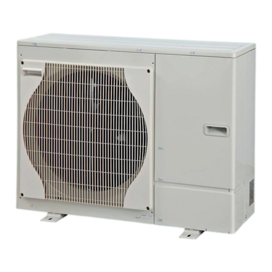
SPLIT-TYPE, AIR TO WATER HEAT PUMP
SERVICE MANUAL
[Model Name]
PUHZ-W50VHA2
Salt proof model
PUHZ-W50VHA2-BS
[Service Ref.]
PUHZ-W50VHA2
PUHZ-W50VHA2R1
PUHZ-W50VHA2-BS
PUHZ-W50VHA2R1-BS
R410A
Revision:
• Added P UHZ-W50VHA2R1
• Some descriptions have been
• Please void OCH605.
Notes:
• This manual describes service
• RoHS compliant products have
CONTENTS
TECHNICAL CHANGES ...................................... 2
1. SAFETY PRECAUTION ................................... 3
2. SPECIFICATIONS ............................................ 6
3. DATA ............................................................... 8
4. OUTLINES AND DIMENSIONS ....................... 9
5. WIRING DIAGRAM ........................................ 10
6. WIRING SPECIFICATIONS ............................ 11
7. REFRIGERANT SYSTEM DIAGRAM ............... 12
8. TROUBLESHOOTING ................................... 13
9. DISASSEMBLY PROCEDURE ...................... 47
PARTS CATALOG (OCB605)
November 2015
No. OCH605
REVISED EDITION-A
and PUHZ-W50VHA2R1-BS
in REVISED EDITION-A.
modified.
data of outdoor unit only.
<G> mark on the spec name
plate.
Advertisement
Table of Contents

Related Manuals for Mitsubishi Electric PUHZ-W50VHA2R1


Summary of Contents for Mitsubishi Electric PUHZ-W50VHA2R1
-
Page 1: Table Of Contents
SPLIT-TYPE, AIR TO WATER HEAT PUMP November 2015 No. OCH605 REVISED EDITION-A SERVICE MANUAL R410A [Model Name] [Service Ref.] PUHZ-W50VHA2 Revision: PUHZ-W50VHA2 • Added P UHZ-W50VHA2R1 and PUHZ-W50VHA2R1-BS PUHZ-W50VHA2R1 in REVISED EDITION-A. • Some descriptions have been modified. Salt proof model • Please void OCH605. PUHZ-W50VHA2-BS PUHZ-W50VHA2-BS Notes: • This manual describes service PUHZ-W50VHA2R1-BS data of outdoor unit only. -
Page 2: Technical Changes
TECHNICAL CHANGES Service ref. have been changed as follows. PUHZ-W50VHA2 PUHZ-W50VHA2R1 PUHZ-W50VHA2-BS PUHZ-W50VHA2R1-BS 1. The installation direction of LEV-B assy has been changed to reduce high frequency noise. OCH605A... -
Page 3: Safety Precaution
SAFETY PRECAUTION 1-1. ALWAYS OBSERVE FOR SAFETY Before obtaining access to terminal, all supply circuits must be disconnected. Preparation before the repair service. • Prepare the proper tools. • Prepare the proper protectors. • Provide adequate ventilation. • After stopping the operation of the air conditioner, turn off the power-supply breaker. •... - Page 4 [1] Cautions for service (1) Perform service after recovering the refrigerant left in the unit completely. (2) Do not release refrigerant in the air. (3) After completing service, charge the cycle with specified amount of refrigerant. [2] Additional refrigerant charge When charging directly from cylinder · Check that cylinder for R410A on the market is a syphon type.
- Page 5 1-3. CAUTIONS FOR REFRIGERANT PIPING WORK Tools for R410A (The following table shows whether conventional tools can be used or not.) Tools and materials R410A tools Can R22 tools be used? Can R407C tools be used? Gauge manifold Air purge, refrigerant charge Tool exclusive for R410A and operation check Charge hose...
-
Page 6: Specifications
SPECIFICATIONS 2-1. SPECIFICATIONS PUHZ-W50VHA2 PUHZ-W50VHA2-BS PUHZ-W50VHA2R1 PUHZ-W50VHA2R1-BS 1[ , 230 V, 50 Hz Nominal water flow rate (Heating mode) L/min 14.3 Heating(A7/W35) (Min.1.50) 5.00 Heating y t i °C (A7/W35) 4.50 °C 1.11 l n i °C (Min.1.50) 5.00 Heating... - Page 7 2-2. AVAILABLE RANGE (WATER FLOW RATE, RETURN WATER TEMP.) Note: If using the unit out of the available range, the parts of unit might be damaged. <Heating> <Applicable Models> • PUHZ-W50VHA2 19.0 Available range • PUHZ-W50VHA2R1 17.0 • PUHZ-W50VHA2-BS 15.0 • PUHZ-W50VHA2R1-BS 13.0 11.0 10.0...
-
Page 8: Data
DATA 3-1. NOISE CRITERION CURVES PUHZ-W50VHA2 PUHZ-W50VHA2R1 PUHZ-W50VHA2-BS PUHZ-W50VHA2R1-BS MODE SPL(dB) LINE COOLING HEATING NC-70 MICROPHONE NC-60 UNIT NC-50 1.5 m NC-40 NC-30 GROUND APPROXIMATE THRESHOLD OF HEARING FOR NC-20 CONTINUOUS NOISE 1000 2000 4000 8000 BAND CENTER FREQUENCIES, Hz 3-2. -
Page 9: Outlines And Dimensions
OUTLINES AND DIMENSIONS PUHZ-W50VHA2 PUHZ-W50VHA2R1 PUHZ-W50VHA2-BS PUHZ-W50VHA2R1-BS Unit: mm OCH605A... -
Page 10: Wiring Diagram
WIRING DIAGRAM PUHZ-W50VHA2 PUHZ-W50VHA2R1 PUHZ-W50VHA2-BS PUHZ-W50VHA2R1-BS SYMBOL NAME SYMBOL NAME Terminal Block C. B. Controller Circuit Board <Power Supply, Indoor/Outdoor> F1, F2 Fuse<T10AL250V> Motor for Compressor F3, F4 Fuse<T6.3AL250V> Fan Motor Switch <Manual Defrost, Defect History Record Reset, Function Switch>... -
Page 11: Wiring Specifications
WIRING SPECIFICATIONS FIELD ELECTRICAL WIRING (power wiring specifications) t i n Outdoor unit power supply ~/N (single), 50 Hz, 230 t i n c r i t i u y t i t i n × Interface unit/Flow temp. controller-Outdoor unit 3 ×... -
Page 12: Refrigerant System Diagram
Refrigerant flow in heating Refrigerant flow in cooling Detail Symbol Part name COMP Compressor DC inverter twin rotary compressor (Mitsubishi Electric Corporation) H/P SW High pressure switch (63H) For protection (OFF:4.15 MPa) Plate HEX Plate Heat Exchange MWA1-28LM (MITSUBISHI) REV/V... -
Page 13: Troubleshooting
TROUBLESHOOTING 8-1. TROUBLESHOOTING <Check code displayed by self-diagnosis and actions to be taken for service (summary)> Present and past check codes are logged, and they can be displayed on the control board of outdoor unit. Actions to be taken for service, which depends on whether or not the trouble is reoccurring in the field, are summarized in the table below. Check the contents below before investigating details. Unit conditions at service Check code Actions to be taken for service (summary) Judge what is wrong and take a corrective action Displayed according to “8-3. SELF-DIAGNOSIS ACTION TABLE”. The trouble is reoccurring. Conduct troubleshooting and ascertain the cause of the Not displayed trouble. 1 Consider the temporary defects such as the work of protection devices in the refrigerant circuit including compressor, poor connection of wiring, noise, etc. Re-check the symptom, and check the installation environment, refrigerant amount, weather when the Logged trouble occurred, matters related to wiring, etc. - Page 14 8-3. SELF-DIAGNOSIS ACTION TABLE <Abnormalities detected when the power is turned on> Check Code Abnormal point and detection method Case Judgment and action 1 No voltage is supplied to terminal 1 Check following items. block (TB1) of outdoor unit. a) Power supply breaker a) Power supply breaker is b) Connection of power supply terminal turned off. block. (TB1) b) Contact failure or c) Connection of power supply terminal disconnection of power block. (TB1) supply terminal c) Open phase (L or N phase) 2 Electric power is not charged 2 Check following items.
- Page 15 Check Code Abnormal point and detection method Case Judgment and action Miswiring of Interface unit/Flow temp. 1 Contact failure or miswiring 1 Check disconnection, looseness or polarity of controller-outdoor unit connecting wire of Interface unit/Flow temp. Interface unit/Flow temp. controller-outdoor 1. Outdoor controller circuit board can controller-outdoor unit unit connecting wire of Interface unit/Flow automatically check the number of connecting wire temp. controller and outdoor units. connected Interface unit/Flow temp. 2 Diameter or length of Interface 2 Check diameter and length of Interface unit/ controller.
- Page 16 <Abnormalities detected while unit is operating> Check Code Abnormal point and detection method Case Judgment and action High pressure (High-pressure switch 1 Decreased water flow 1–5 Check water circuit and repair the defect. 63H operated) 2 Clogged filter of water pipe Abnormal if high-pressure switch 63H 3 Dirt of plate heat exchanger operated (*) during compressor operation. 4 Locked water pump *4.15 MPa 5 Malfunction of water pump 6 Clogged or broken pipe 6 Check piping and repair the defect. 63H: High-pressure switch 7 Locked outdoor fan motor 7–0 Check outdoor unit and repair the defect.
- Page 17 Check Code Abnormal point and detection method Case Judgment and action Open/short of outdoor unit thermistors 1 Check connection of connector (TH3, TH32, 1 Disconnection or contact failure TH34, TH6/TH7) on the outdoor controller circuit (TH3, TH6, TH32, TH34, TH6, TH7, and TH8) of connectors board. Check connection of connector (CN6) on Abnormal if open or short is detected Outdoor controller circuit board: the outdoor power circuit board. Check the lead during compressor operation.
- Page 18 Check Code Abnormal point and detection method Case Judgment and action To find out the details about U9 error, turn ON SW2-1, 2-2, 2-3, 2-4, 2-5 and 2-6 when U9 error occurs. Detailed To find out the detail history (latest) about U9 error, turn ON SW2-1, 2-2 and 2-6. codes Refer to "8-7. OUTDOOR UNIT OPERATION MONITOR FUNCTION". Overvoltage error 1 A bnormal increase in power 1 Check the field facility for the power supply. 2 Correct the wiring (U . V . W phase) to • Increase in DC bus voltage to source voltage compressor. Refer to "8-6. TEST POINT W50V: 400 V 2 Disconnection of compressor wiring DIAGRAM" (Outdoor power circuit board).
- Page 19 Check Code Abnormal point and detection method Case Judgment and action Overheat protection 1 Defective outdoor fan (fan 1 Check outdoor unit air passage. Abnormal if outdoor liquid thermistor motor) or short cycle of out- (TH3) detects 70: or more or condensing door unit during cooling opera- temperature of pressure sensor (63HS) tion 23 Turn the power off and on again to check detects 70: or more during compressor the check code. If U4 is displayed, follow 2 Defective outdoor liquid operation. thermistor (TH3) the U4 processing direction. 3 Defective outdoor controller circuit board 4 Defective pressure sensor 4 Check pressure by microcomputer. (Pressure sensor/ 63HS) (SW2: Refer to "8-7. OUTDOOR UNIT OPERATION MONITOR FUNCTION".) Compressor overcurrent interruption 1 Decrease of power supply 1 Check facility of power supply.
- Page 20 Check Code Abnormal point and detection method Case Judgment and action Remote controller transmission error 1 Check disconnection or looseness of 1 Contact failure at transmission (E0)/signal receiving error (E4) wire of remote controller Interface unit/Flow temp. controller unit or 1 Abnormal if main or sub remote 2 All remote controllers are set transmission wire of remote controller. controller cannot receive any as “sub” remote controller.
- Page 21 Check Code Abnormal point and detection method Case Judgment and action Interface unit/Flow temp. controller- 1 Check disconnection or looseness of 1 Contact failure of Interface unit/Flow temp. controller- outdoor unit communication error Interface unit/Flow temp. controller-outdoor outdoor unit connecting wire (Signal receiving error) unit connecting wire of Interface unit/Flow 2 Defective communication cir- (Outdoor unit) temp. controller or outdoor unit. cuit of outdoor controller circuit (1) Abnormal if outdoor controller circuit 2–4 Turn the power off, and on again to board...
- Page 22 Check Code Abnormal point and detection method Case Judgment and action Pipe temperature 1 Leakage or shortage of 1 Check intake superheat. Abnormal if the following conditions are refrigerant Check leakage of refrigerant. detected for continuously 3 minutes after compressor starts operating for 10 minutes. 2 Malfunction of linear expansion 2 Check linear expansion valve. 1. Cooling mode valve TH7 [ 2: and 63HS− TH3−TH7 [ 4: or T −TH3 < 0: and 3 Refrigerant circuit is clogged 63HS...
- Page 23 8-4. HOW TO CHECK THE PARTS PUHZ-W50VHA2 PUHZ-W50VHA2R1 PUHZ-W50VHA2-BS PUHZ-W50VHA2R1-BS Parts name Check points Disconnect the connector then measure the resistance with a tester. Thermistor (TH3) <Liquid> (At the ambient temperature of 10 to 30:) Thermistor (TH4) <Discharge> Normal Abnormal Thermistor (TH6) <Plate HEX Liquid>...
- Page 24 8-4-1. Check method of DC fan motor (fan motor/outdoor controller circuit board) Notes · High voltage is applied to the connector (CNF1, 2) for the fan motor. Pay attention to the service. · Do not pull out the connector (CNF1, 2) of the motor with the power supply on. (It may damage the outdoor controller circuit board and fan motor.) Self check Symptom: The outdoor fan cannot rotate.
- Page 25 8-5. HOW TO CHECK THE COMPONENTS <Thermistor feature chart> Low temperature thermistors • Thermistor <Liquid> (TH3) • Thermistor <Plate HEX Liquid> (TH6) • Thermistor <Ambient> (TH7) Thermistor R0 = 15 k" ± 3% B constant = 3480 ± 2% =15exp{3480( 273+t – 273 )} 0: 15 k" 4.3 k" 10: 9.6 k" 40: 3.0 k" 20: 6.3 k" 25: 5.2 k" -20 -10 0 10 20 30 40 50 Temperature (:) Medium temperature thermistor • Thermistor <Heat Sink> (TH8)
- Page 26 Low temperature thermistor • Thermistor <Inlet Water> (TH32) Thermistor R0 = 15 k" ± 2.5% B constant = 3450 ± 2% =15exp{3450( 273+t – 273 )} 0: 15 k" 4.3 k" 10: 9.6 k" 40: 3.0 k" 20: 6.3 k" 25: 5.2 k" -20 -10 10 20 30 40 50 Temperature(:) <HIGH PRESSURE SENSOR> Vout (V) MULTI CONTROLLER BOARD 5 V DC Vout MICRO PROCESSOR...
- Page 27 Outdoor controller board 12 V DC Gray Drive circuit Orange Linear expansion valve Yellow (1) Operation summary of the linear expansion valve • Linear expansion valve opens/closes through stepping motor after receiving the pulse signal from the outdoor controller circuit board. Black • Valve position can be changed in proportion to the number of pulse signal. Connector LEV-A <Connection between the outdoor controller circuit board and the linear expansion valve> LEV-B LEV-C Outdoor controller board 12 V DC Gray Drive circuit Orange Yellow Black Connector LEV-A...
- Page 28 (3) How to attach and detach the coil of linear expansion valve <Composition> Linear expansion valve is separable into the main body and the coil as shown in the diagram below. Main body Stopper Coil Lead wire <How to detach the coil> Hold the lower part of the main body (shown as A) firmly so that the main body does not move and detach the coil by pulling it upward. Be sure to detach the coil holding main body firmly. Otherwise pipes can bend due to stress. <How to attach the coil> Hold the lower part of the main body (shown as A) firmly so that the main body does not move and attach the coil by inserting it downward into the main body. Then securely attach the coil stop-...
- Page 29 8-6. TEST POINT DIAGRAM Outdoor controller circuit board PUHZ-W50VHA2 PUHZ-W50VHA2R1 <CAUTION> TEST POINT 1 is high voltage. PUHZ-W50VHA2-BS PUHZ-W50VHA2R1-BS CNDM Manual defrost, 1–2: detect history Input of low-level Operation record reset sound priority mode monitor function 21S4 4-way valve Model select Function switch Transmission to out- door power circuit Function switch board (CN4) Connection for option...
- Page 30 Outdoor power circuit board Brief Check of DIP-IPM and D.B. PUHZ-W50VHA2 Usually, they are in a state of being short-circuited if they are broken. Measure the resistance in the following points (connectors, etc.). If they PUHZ-W50VHA2R1 are short-circuited, it means that they are broken. PUHZ-W50VHA2-BS 1. Check of DIP-IPM P2 - U , P2 - V , P2 - W , N2 - U , N2 - V , N2 - W PUHZ-W50VHA2R1-BS 2. Check of IGBT (Q600) DB3 + - DB3 − 3. Check of diode bridge P2 - L , P2 - N , N2 - L , N2 - N Note: The marks N1 , N2 , P1 , P2 , U , V , W , L , N , + and − shown in the diagram are not actually printed on the board. U, V, W R/L1, S/N1 Connect to the CNAC1, CNAC Connect to the Voltage of 230 V AC compressor (MC) Connect to the out-...
- Page 31 8-7. OUTDOOR UNIT OPERATION MONITOR FUNCTION Operation indicator SW2: Indicator change of self diagnosis ■ The black square ( ) indicates a switch position. Display detail Explanation for display Unit SW2 setting 2 3 4 5 6 <Digital indicator LED3 working details> (Be sure that the 1 to 6 in the SW2 are set to OFF.) 1 second (1) Display when the power supply is ON. interval When the power supply is ON, blinking displays by turns. Wait for 10 seconds at the longest. (2) When the display lights (Normal operation) 1 Operation mode display (Lighting) LED3 (Initial setting) 2 3 4 5 6 The ones digit : Relay output...
- Page 32 ■ The black square ( ) indicates a switch position. SW2 setting Display detail Explanation for display Unit Pipe temperature/Liquid (TH3) −40 to 90 −40 to 90 (When the coil thermistor detects 0: or below, “–” and temperature are displayed by turns.) (Example) When −10:; 2 3 4 5 6 0.5 s 0.5 s 2 s Discharge temperature (TH4) 3 to 217 3 to 217 (When the discharge thermistor detects 100: or more, hundreds digit, tens digit and ones digit are displayed by turns.) (Example) When 105:; 2 3 4 5 6 0.5 s 0.5 s 2 s Fan steps 0 to 10 0 to 10 Step 2 3 4 5 6 Compressor ON/OFF 0 to 9999 (When the number of times is 100 or more,...
- Page 33 ■ The black square ( ) indicates a switch position. SW2 setting Display detail Explanation for display Unit Pipe temperature/Liquid (TH3) when −40 to 90 error occurred (When the coil thermistor detects 0: or below, “–” −40 to 90 and temperature are displayed by turns.) (Example) When −15:; 0.5 s 0.5 s 2 s 2 3 4 5 6 Discharge temperature (TH4) when error 3 to 217 occurred (When the temperature is 100: or more, the 3 to 217 hundreds digit, tens digit and ones digit are displayed by turns.) (Example) When 130:; 2 3 4 5 6 0.5 s 0.5 s 2 s Compressor current when error occurred 0 to 50 0 to 50...
- Page 34 ■ The black square ( ) indicates a switch position. Explanation for display SW2 setting Display detail Unit Outdoor unit setting information • The tens digit (Total display for applied setting) Setting details Display details H·P / Cooling only 0 : H·P 1 : Cooling only Single phase / 3 phase 0 : Single phase 2 : 3 phase •...
- Page 35 ■ The black square ( ) indicates a switch position. Display detail Explanation for display Unit SW2 setting 0 to FFFE (in hexadecimal notation) Number of defrost cycles 0 to FFFE (When more than FF in hex (255 in decimal), the number is displayed in order of 16 's and 16 's, and 's and 16 's places. (Example) When 5000 cycles; 0.5 s 0.5 s 2 s 2 cycles 2 3 4 5 6 0 to 500 Input current of outdoor unit (When it is 100 or more, hundreds digit, tens digit 0 to 500 0.1 A and ones digit are displayed by turns.) 2 3 4 5 6 0 to 500 LEV-B opening pulse (When it is 100 pulse or more, hundreds digit, tens...
- Page 36 ■ The black square ( ) indicates a switch position. Display detail SW2 setting Explanation for display Unit When no error history, “0” and “– –“ are displayed by Error history (3) (Oldest) turns. Faulty unit number and check code are Code displayed alternately. display 2 3 4 5 6 3: Liquid pipe thermistor (TH3) 3: Water inlet temp. thermistor (TH32) Error thermistor display 6: Plate HEX liquid pipe thermistor (TH6) 7: Ambient temp. thermistor (TH7) When there is no error thermistor, 8: Heat sink thermistor (TH8) Code “–“ is displayed. 4: Discharge thermistor (TH4) display 34: Comp. surface thermistor (TH34) 2 3 4 5 6 0 to 225...
- Page 37 ■ The black square ( ) indicates a switch position. SW2 setting Display detail Explanation for display Unit Outdoor heat sink temperature (TH8) −40 to 200 when error occurred. (When the temperature is 0°C or less, “–” and temperature are displayed by turns.) −40 to 200 (When the temperature is 100°C or more, hundreds 2 3 4 5 6 digit, tens digit and ones digit are displayed by turns.) Discharge superheat (SHd) when error 0 to 255 occurred. (When the temperature is 100°C or more, hundreds 0 to 255 digit, tens digit and ones digit are displayed by turns.) Cooling and Heating: SHd=TH4−T (Example) When 150°C; 63HS 2 3 4 5 6 0.5 s 0.5 s 2 s Sub cool (SC) when error occurred. 0 to 130 0 to 130 (When the temperature is 100°C or more, hundreds...
- Page 38 ■ The black square ( ) indicates a switch position. Explanation for display Unit SW2 setting Display detail 3 to 217 Comp. surface temperature (TH34) (When the temperature is 100: or more, the 3 to 217 hundreds digit, tens digit and ones digit are displayed by turns.) (Example) When 130:; 2 3 4 5 6 0.5 s 0.5 s 2 s Requested capacity step (Q STEP) 0 to 7 0 to 7 Step 2 3 4 5 6 U9 error details (To be shown while Description Display error call is deferred.) Normal Overvoltage error Undervoltage error Input current sensor error Abnormal power synchronous signal...
- Page 39 OCH605A...
- Page 40 8-8. FUNCTION OF SWITCHES PUHZ-W50VHA2 PUHZ-W50VHA2R1 PUHZ-W50VHA2-BS PUHZ-W50VHA2R1-BS Switch Selection Function Default setting* Function details Effective timing Mark ON (with) OFF (without) Manual defrost ON to start usual setting Switch ON to force defrosting Always Switch ON to clear (erase) the following status: To clear error history ON to clear usual setting Always (1)Check codes and Suspension flags in RAM (2)Check codes and Suspension flags in EEPROM No function –...
- Page 41 8-9. Request code list Certain indoor/outdoor combinations do not have the request code function; therefore, no request codes are displayed. Refer to indoor unit service manual for how to use the controllers and request codes for indoor unit. Description Request content Unit Remarks (Display range)
- Page 42 Description Request content Unit Remarks (Display range) Outdoor unit-Control state – Refer to 8-9-1.Detail Contents in Request Code. Compressor-Frequency control state Refer to 8-9-1.Detail Contents in Request Code. – Outdoor unit-Fan control state Refer to 8-9-1.Detail Contents in Request Code. –...
- Page 43 Description Request content Unit Remarks (Display range) Error history 1 (latest) Displays error history. (" --" is displayed if no history is present.) Code Error history 2 (second to last) Displays error history. (" --" is displayed if no history is present.) Code Error history 3 (third to last) Displays error history.
- Page 44 8-9-1. Detail Contents in Request Code [Operation state] (Request code :" 0") Relay output state Power currently Data display Display Compressor 4-way valve Solenoid valve supplied to compressor – – – – Relay output state Operation mode Operation mode Display Operation mode STOP •...
- Page 45 [Actuator output state] (Request code :"54") Data display Actuator output state 1 Actuator output state 2 Actuator output state Actuator output state Compressor is Display 4-way valve Compressor Display warming up [Error content (U9)] (Request code :"55 ") Data display Error content 1 Error content 2 Error content...
- Page 46 [Outdoor unit – Setting information] (Request code : "71") Setting information 1 Data display Display Defrost mode Setting information 1 Standard Setting information 2 For high humidity Setting information 2 Single-/ Heat pump/ Display cooling only 3-phase Heat pump Single-phase Cooling only Heat pump 3-phase...
-
Page 47: Disassembly Procedure
DISASSEMBLY PROCEDURE PUHZ-W50VHA2 PUHZ-W50VHA2-BS OPERATING PROCEDURE PHOTOS Top panel fixing screws 1. Removing the service panel and top panel Photo 1 Top panel (1) Remove 3 screws (5 12) and slide the hook on the right × downward to remove the service panel. (2) Remove screws (3 for front, 3 for rear/5 12) of the top × Slide panel and remove it. Service panel Note: When removing service panel and top panel at the same time, count one less screw since they share a Service panel screw. fixing screws Cover panel (front) Fan grille... - Page 48 OPERATING PROCEDURE PHOTOS 4. Removing the thermistor <Plate HEX Liquid> (TH6) Photo 5 (1) Remove the service panel. (See Photo 1) (2) Remove the top panel. (See Photo 1) (3) Remove 2 screws (5 12) and remove the cover panel (front). (See Photo 1) Thermistor × <Liquid>(TH3) (4) Remove 3 valve bed fixing screws (4 10) and remove the × valve bed. Remove 3 side panel (R) fixing screws (5 12) × and remove the side panel (R). (See Photo 4) (5) Disconnect the connector TH7/6 (RD) on the controller circuit board. (6) Loosen the clamps for the lead wire. Plate heat exchanger (7) Pull out the thermistor <Plate HEX Liquid> (TH6) from Thermistor the sensor holder. <Plate HEX Liquid> Note: In case of replacing thermistor <Plate HEX Liquid>(TH6), (TH6) replace it together with thermistor<Ambient>...
- Page 49 OPERATING PROCEDURE PHOTOS 8. Removing the solenoid valve coil <4-way valve> (21S4) Photo 9 and linear expansion valve coil (LEV-A, LEV-B) High pressure sensor (1) Remove the service panel. (See Photo 1) Solenoid valve High pressure (2) Remove the top panel. (See Photo 1) <4-way> (21S4) switch 4-way valve (3) Remove the electrical parts box. (See Photo 4) [Removing the solenoid valve coil <4-way valve> ] Linear Expansion (4) Remove solenoid valve coil <4-way valve> fixing screw Valve (M4 x 6). (LEV-A) (5) Remove the solenoid valve coil <4-way valve>. Linear (6) Disconnect the connector 21S4 (GN) on the controller cir- Expansion...
- Page 50 OPERATING PROCEDURE PHOTOS Photo 10 Terminal cover 13. Removing the compressor (MC) (1) Remove the service panel. (See Photo 1) (2) Remove the top panel. (See Photo 1) Lead wire for (3) Remove 2 screws (5 12) and remove the cover panel (front). × compressor (4) Remove the electrical parts box. (See Photo 4) (5) Remove 3 screws (4 10) and remove the valve bed. × (See Photo 10) (6) Remove 3 screws (5 12) in the rear of the unit and × remove the side panel (R). (See Photo 4) (7) Remove 5 screws (1: 4 10, 4: 5 12) and remove the × × front panel. (See Photo 2) (8) Remove 3 screws (4 10) and remove the separator. (See × Photo 4) Compressor (9) Remove the terminal cover and remove the lead wire for (MC) compressor.
- Page 51 OPERATING PROCEDURE PHOTOS & ILLUSTRATION 16. Removing the controller circuit board (C.B.): Figure 1 Figure 1, Photo 12 (1) Remove all lead wire connectors on controller circuit board Power circuit (C.B.). board (P.B.) CNF1, CNDC, CNAC, CN2, CN4, CNS, Reactor 21S4, 63H, 63HS, LEV-A, LEV-B, (ACL) TH32, TH7/6, TH3, TH4, TH34 Controller circuit board (C.B.) (2) Remove controller circuit board. (5 supports) 17. Removing the power circuit board (P.B.) : Figure 1, Photo 12 (1) Remove CN2, CN4, CNDC, CNAC1, CNAC2 lead wire connectors from controller circuit board (C.B.).
- Page 52 PUHZ-W50VHA2R1 PUHZ-W50VHA2R1-BS OPERATING PROCEDURE PHOTOS Top panel fixing screws 1. Removing the service panel and top panel Photo 1 Top panel (1) Remove 3 screws (5 12) and slide the hook on the right × downward to remove the service panel. (2) Remove screws (3 for front, 3 for rear/5 12) of the top × Slide panel and remove it. Service panel Note: When removing service panel and top panel at the same time, count one less screw since they share a Service panel screw. fixing screws Cover panel (front)
- Page 53 OPERATING PROCEDURE PHOTOS 4. Removing the thermistor <Plate HEX Liquid> (TH6) Photo 5 (1) Remove the service panel. (See Photo 1) (2) Remove the top panel. (See Photo 1) (3) Remove 2 screws (5 12) and remove the cover panel (front). (See Photo 1) Thermistor × <Liquid>(TH3) (4) Remove 3 valve bed fixing screws (4 10) and remove the × valve bed. Remove 3 side panel (R) fixing screws (5 12) × Plate heat and remove the side panel (R). (See Photo 4) exchanger (5) Disconnect the connector TH7/6 (RD) on the controller circuit board. (6) Loosen the clamps for the lead wire. Thermistor (7) Pull out the thermistor <Plate HEX Liquid> (TH6) from <Plate HEX Liquid> (TH6) the sensor holder. Note: In case of replacing thermistor <Plate HEX Liquid>(TH6), Plate heat exchang- replace it together with thermistor<Ambient>...
- Page 54 OPERATING PROCEDURE PHOTOS 8. Removing the solenoid valve coil <4-way valve> (21S4) Photo 9 High pressure and linear expansion valve coil (LEV-A, LEV-B) sensor (1) Remove the service panel. (See Photo 1) Solenoid valve (2) Remove the top panel. (See Photo 1) High pressure <4-way> (21S4) (3) Remove the electrical parts box. (See Photo 4) switch 4-way valve [Removing the solenoid valve coil <4-way valve> ] (4) Remove solenoid valve coil <4-way valve> fixing screw (M4 x 6). Linear (5) Remove the solenoid valve coil <4-way valve>. Expansion (6) Disconnect the connector 21S4 (GN) on the controller cir- Valve cuit board.
- Page 55 OPERATING PROCEDURE PHOTOS Photo 10 Terminal cover 13. Removing the compressor (MC) (1) Remove the service panel. (See Photo 1) (2) Remove the top panel. (See Photo 1) Lead wire for (3) Remove 2 screws (5 12) and remove the cover panel (front). × compressor (4) Remove the electrical parts box. (See Photo 4) (5) Remove 3 screws (4 10) and remove the valve bed. × (See Photo 10) (6) Remove 3 screws (5 12) in the rear of the unit and × remove the side panel (R). (See Photo 4) (7) Remove 5 screws (1: 4 10, 4: 5 12) and remove the × × front panel. (See Photo 2) (8) Remove 3 screws (4 10) and remove the separator. (See × Photo 4) Compressor (9) Remove the terminal cover and remove the lead wire for (MC) compressor.
- Page 56 OPERATING PROCEDURE PHOTOS & ILLUSTRATION 16. Removing the controller circuit board (C.B.): Figure 1 Figure 1, Photo 12 (1) Remove all lead wire connectors on controller circuit board Power circuit (C.B.). board (P.B.) CNF1, CNDC, CNAC, CN2, CN4, CNS, Reactor 21S4, 63H, 63HS, LEV-A, LEV-B, (ACL) TH32, TH7/6, TH3, TH4, TH34 Controller circuit board (C.B.) (2) Remove controller circuit board. (5 supports) 17. Removing the power circuit board (P.B.) : Figure 1, Photo 12 (1) Remove CN2, CN4, CNDC, CNAC1, CNAC2 lead wire connectors from controller circuit board (C.B.).
- Page 57 OCH605A...
- Page 58 HEAD OFFICE : TOKYO BLDG., 2-7-3, MARUNOUCHI, CHIYODA-KU, TOKYO 100-8310, JAPAN Copyright 2015 MITSUBISHI ELECTRIC CORPORATION Distributed in Nov. 2015 No. OCH605 REVISED EDITION-A Distributed in Jul. 2015 No. OCH605 New publication, effective Nov. 2015 Made in Japan Specifications are subject to change without notice.
- Page 59 Related Links Model Number: PUHZ-W50VHA-BS 14 Apartments, London 42 Flats, Lancashire Bungalow, Cambridgeshire Coastline Housing, Cornwall Community Project, Isle of Wight Dairy Farm and Barn, Northamptonshire Ecodan FTC3 / FTC4 Homeowner Quick Start Guide Version 2 Ecodan FTC5 Homeowner Quick Start Guide Ecodan Heating for Domestic Applications Brochure 2016 Ecodan Help Videos For Homeowners...
- Page 60 Ecodan FTC5 Databook (M-P0729)