Biostar M7NCD User Manual
Biostar m7ncd motherboard: user guide
Hide thumbs
Also See for M7NCD:
- Bios setup manual (29 pages) ,
- Datasheet (47 pages) ,
- User manual (41 pages)
Table of Contents
Advertisement
M
7
N
C
D
M
7
N
C
D
M
7
N
C
D
FCC Information and Copyright
This equipment has been tested and found to comply with the limits of a
Class B digital device, pursuant to Part 15 of the FCC Rules. These limits
are
designed
to
provide
reasonable
protection
against
harmful
interference in a residential installation. This equipment generates, uses
and can radiate radio frequency energy and, if not installed and used in
accordance with the instructions, may cause harmful interference to radio
communications. There is no guarantee that interference will not occur in
a particular installation.
The vendor makes no representations or warranties with respect to the
contents here of and specially disclaims any implied
of
warranties
merchantability or fitness for any purpose. Further the vendor reserves
the right to revise this publication and to make changes to the contents
here of without obligation to notify any party beforehand.
Duplication of this publication, in part or in whole, is not allowed without
first obtaining the vendor's approval in writing.
The content of this user's manual is subject to be changed without notice
and we will not be responsible for any mistakes found in this user's
manual. All the brand and product names are trademarks of their
respective companies.
i
Advertisement
Table of Contents

Related Manuals for Biostar M7NCD


Summary of Contents for Biostar M7NCD
- Page 1 FCC Information and Copyright This equipment has been tested and found to comply with the limits of a Class B digital device, pursuant to Part 15 of the FCC Rules. These limits designed provide reasonable protection against harmful interference in a residential installation. This equipment generates, uses and can radiate radio frequency energy and, if not installed and used in accordance with the instructions, may cause harmful interference to radio communications.
-
Page 2: Table Of Contents
How to setup Jumper ... 5 CPU Installation ... 5 DDR DIMM Modules: DIMMB1, DIMMB2 ... 6 Jumpers, Headers, Connectors & Slots... 7 DEUTSCH ...14 Spezifikationen von M7NCD ... 14 Verpackungsinhalt... 15 Einstellung der Jumper... 16 Installation der CPU... 16 DDR-DIMM-Modules: DIMMB1, DIMMB2 ... 17 Jumpers, Headers, Anschlüsse &... -
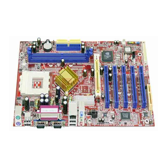
Page 3: Layout Of M7Ncd
Layout of M7NCD ※NOTE: ●represents the first pin. -
Page 4: Component Index
Component Index A. Power Source Selection for Keyboard and Mouse (JKBV1) B. Power Source Selection for USB (JUSBV1) C. Back Panel Connector D. ATX Power Connector (JATXPWER1) E. Safe/ User Mode Selection (JCLK) F. Power Source Selection for USB (JUSBV2) G. -
Page 5: English
English M7NCD Features A. Hardware Provides Socket-462. ® Supports the AMD processor up to XP 3200+. Front Side Bus at 266/333/400 MHz. Chipset North Bridge: nVIDIA nFORCE2 400. South Bridge: nVIDIA nFORCE2 MCP/ MCP-T. Main Memory Supports up to 2 DDR devices. -
Page 6: Package Contents
AC’97 2.2 interface. Supports 6 channels. On Board Peripherals a. Rear side 2 serial ports. 1 parallel port. (SPP/EPP/ECP mode) Audio ports in vertical position. 1 LAN port. (optional) PS/2 mouse and PS/2 keyboard. 4 USB2.0 ports. 1 IEEE 1394A (FireWire) Connector. (optional) b. -
Page 7: How To Setup Jumper
How to setup Jumper The illustration shows how jumpers are setup. When the Jumper cap is placed on pins, the jumper is “close”. If no jumper cap is placed on the pins, the jumper is ”open”. The illustration shows a 3-pin jumper whose pin 1and 2 are “close” when jumper cap is placed on these 2 pins. -
Page 8: Ddr Dimm Modules: Dimmb1, Dimmb2
CPU Fan Header: JCFAN1 Pin No. JCFAN1 System Fan Header: JSFAN1 Pin No. JSFAN1 DDR DIMM Modules: DIMMB1, DIMMB2 DRAM Access Time: 2.5V Unbuffered DDR 266/333/400 MHz Type required. DRAM Type: 64MB/ 128MB/ 256MB/ 512MB/ 1GB DIMM Module (184 pin) Total Memory Size with Unbuffered DIMMs DIMM Socket DDR Module... -
Page 9: Jumpers, Headers, Connectors & Slots
The first hard drive should always be connected to IDE1. Peripheral Component Interconnect Slots: PCI 1-5 This motherboard is equipped with 5 standard PCI slots. PCI stands for Peripheral Component Interconnect, and it is a bus standard for expansion cards. This PCI slot is designated as 32 bits. -
Page 10: Front Panel Connector: Jpanel1
Front Panel Connector: JPANEL1 PWR_LED JPANEL1 (+) (-) HLED Assignment Function Speaker Connector Speaker HDD LED (+) Hard Drive HDD LED (-) Ground Reset Button Reset Control IrDA Connector IRTX Front USB Header: JUSB3 Assignment +5V(fused) USBP4- USBP4+ JUSB3 Wake On LAN Header: JWOL1 JWOL1 ON/OFF Assignment... - Page 11 Power Source Selection for Keyboard and Mouse: JKBV1 JKBV1 Assignment Pin 1-2 close +5V Standby Voltage Pin 2-3 close Note: In order to support this function “Power-on system via keyboard and mouse”, “JKBV1” jumper cap should be placed on pin 2-3. Power Source Selection for USB: JUSBV1/ JUSBV2/ JUSBV3 JUSBV1/JUSBV2/ Assignment...
- Page 12 Clear CMOS Jumper: JCMOS JCMOS Pin 1-2 Close Pin 2-3 Close The following procedures are for resetting the BIOS password. It is important to follow these instructions closely. ※ Clear CMOS Procedures: 1. Remove AC power line. 2. Set the jumper to “Pin 2-3 Close”. 3.
- Page 13 Front Panel Audio Header: JF_AUDIO1 Assignment Mic In/ Center Mic Power/ Bass Right Line Out/ Speaker Out Right Reserved Left Line Out/ Speaker Out Left Right Line In/ Right Rear Speaker Left Line In/ Left Rear Speaker Safe/ User Mode Selection: JCLK JCLK Pin 1-2 Close Pin 1-2 Open...
- Page 14 Digital Audio Connector: J_SPDIF1 (optional) Game Header: JGAME1 (optional) Assignment Joystick B Button 1 Joystick B Coordinate X MIDI Output Joystick B Coordinate Y Joystick B Button 2 MIDI Input Front 1394 Header: J1394A (optional) Assignment J1394A CNR Codec/ Onboard Selection: J_CODECSEL J_CODECSEL Pin 1-2 Close Assignment...
- Page 15 Pin 2-3 Close Back Panel Connectors J1394_USB1 JPRNT1 1394 PS/2 (optional) Mouse Parallel Port PS/2 COM1 Keyboard JCOM1 JKBMS1 CNR Codec is used JUSBLAN1 (optional) Line In Speaker Out MIC In COM2 JCOM2 JAUDIO...
-
Page 16: Deutsch
Deutsch Spezifikationen von M7NCD A. Hardware Unterstützung für Sockel 462. Unterstützung für den AMD® Prozessor bis zu XP 3200+. FSB von 266/333/400 MHz. Chipsatz Northbridge: nVIDIA nFORCE2 400. Southbridge: nVIDIA nFORCE2 MCP/ MCP-T. Hauptspeicher Unterstützung für 2 DDR Geräte. Unterstützung für 266/333/400 MHz (ohne ECC) DDR Geräte. -
Page 17: Verpackungsinhalt
Onboard AC’97 Sound Codec Chip: ALC650. Entspricht der Spezifikation von AC’97. Unterstützung für AC97 2.2 Interface. Unterstützung für 6-Kanal Audio. Onboard-Peripheriegeräte a. Rückwand 2 serielle Schnittstellen. 1 parallele Schnittstelle. (SPP/EPP/ECP-Modus) Audio-Ports auf vertikale Position. 1 LAN-Port. (optional) Uerstützung für PS/2-Maus und PS/2-Tastatur. 4 USB2.0-Ports. -
Page 18: Einstellung Der Jumper
Treiber CD für Installation X 1 StudioFun! Anwendung CD X 1 (optional) Einstellung der Jumper Die Abbildung verdeutlicht, wie Jumper eingestellt werden. Pins werden durch die Jumper-Kappe verdeckt, ist der Jumper ”geschlossen”. Keine Pins werden durch die Jumper-Kappe verdeckt, ist der Jumper “geöffnet”. Die Abbiildung zeigt einen 3-Pin Jumper dessen Pin1 und Pin2 ”geschlossen“... -
Page 19: Ddr-Dimm-Modules: Dimmb1, Dimmb2
CPU-Lüfter Header: JCFAN1 JCFAN1 System-Lüfter Header: JSFAN1 JSFAN1 DDR-DIMM-Modules: DIMMB1, DIMMB2 DRAM-Zugriffszeit: 2.5V Unbuffered DDR 266/333/400 MHz Typ erfordlich. DRAM-Typ: 64MB/ 128MB/ 256MB/ 512MB/ 1GB DIMM-Module (184-Pin) Gesamte Speichergröße von Unbuffered-DIMMs DIMM-Sockel Standort DIMMB1 64MB/128MB/256MB/512MB/1GB DIMMB2 64MB/128MB/256MB/512MB/1GB Nur als Referenz Installation von DDR-Modul Öffnen Sie einen DIMM-Slots, indem Sie die seitlich Chips nach außen drücken. -
Page 20: Jumpers, Headers, Anschlüsse & Slots
4 Festplatten angeschlossen werden können. Die erste Festplatte sollte immer an IDE1 angeschlossen werden. Peripheral Component Interconnect Slots: PCI1-5 Dieses Motherboard ist mit 5 standardmäßigen PCI-Slots ausgestattet. PCI steht für Peripheral Component Interconnect und bezieht sich auf einem Busstandard für Erweiterungskarten, Schnittstellen ersetzt hat. - Page 21 Stromversorgungsanschluss: JATXPWER1 JATXPWER1 +5V reservierte Anschlüsse für die Vorderseite: JPANEL1 PWR_LED JPANEL1 Belegung Funktion Lautsprecher- Kein Anschluss Kein Lautsprecher HDD LED (+) Festplatte HDD LED (-) Masse Rückstell- knopf Reset-Kontroll Kein Kein IrDA- Anschluss IRTX Belegung Belegung +3.3V +3.3V +3.3V -12V Masse Masse...
- Page 22 Front USB Header: JUSB3 +5V(geschmelzt) JUSB3 Wake On LAN Header: JWOL1 JWOL1 Auswahl von Stromsmodi für Tastatur/ Maus: JKBV1 JKBV1 Pin-Belegung Pin 1-2 geschlossen +5V reservierte Pin 2-3 Spannung geschlossen Anmerkung: Um die Funktion ─ “Erwecken durch Tastatur/Maus“ ─ zu aktivieren, müssen Pins 2-3 von JKBV1 durch die Jumperkappe verdeckt werden.
- Page 23 Auswahl von Stromsmodi für USB: JUSBV1/ JUSBV2/JUSBV3 JUSBV1/JUSBV2/ Pin-Belegung JUSBV3 Pin 1-2 geschlossen Pin 2-3 geschlossen +5V reservierte Spannung Anmerkung: Um die Funktion ─ “Erwecken durch USB-Geräte“ ─ zu aktivieren, müssen Pins 2-3 von JUSBV1/JUSBV2/JUSBV3 durch die Jumperkappe verdeckt werden. Jumper zum Löschen des CMOS: JCMOS JCMOS Pin 1-2 geschlossen...
- Page 24 ※ Prozeduren zum Löschen des CMOS: 1. Ausschalten Sie das System. 2. Lassen Sie Pin 2-3 von JCOMS1 geshclossen sein. 3. Bitte warten Sie 15 Sekunden. 4. Lassen Sie Pin 1-2 von JCOMS1 geshclossen sein. 5. Einschalten Sie das System wieder. 6.
- Page 25 Reservieret für spät. Verwendung durch Kopfhörer-Verstärker Audio-Signal des linken Kanals zur Vorderseite / Lautsprecher-Signal des linken Kanals zur Vorderseite Audio-Signal des rechten Kanals von der Vorderseite / Lautsprecher-Signal des rechten Kanals von der Vorderseite Audio-Signal des linken Kanals von der Vorderseite/ Lautsprecher-Signal des linken Kanals von der Vorderseite...
- Page 26 Game Header: JGAME1 (optional) Belegung Joystick B Knopf 1 Joystick B Koordierung X MIDI Ausgabe Joystick B Koordierung Y Joystick B Knopf 2 MIDI Eingabe Kein Front 1394 Header: J1394A (optional) J1394A Auswahl CNR /Onboard-Codec: J_CODECSEL J_CODECSEL Pin 1-2 geschlossen Pin 2-3 geschlossen Belegung Joystick A Knopf 1...
- Page 27 Anschlüsse für die Rückwand JUSBLAN1 J1394_USB1 JPRNT1 1394 PS/2 (optional) (optional) Parallel Port Maus Line In Speaker Out MIC In PS/2 COM1 COM2 Tastatur JCOM1 JCOM2 JAUDIO JKBMS1...
-
Page 28: Watchdog Technology
Watchdog Technology It is important to know that when overclocking, the system can be at a vulnerable state. Therefore, the BIOSTAR Watchdog Technology was designed to protect your PC under dangerous over-clock situations. Any over-clocking that reaches the threshold settings, the Watchdog Technology will disable your system from rebooting in the BIOS setting. -
Page 29: Studiofun
StudioFun! Introduction StudioFun! is a media-player based on optimized GNU/Linux distribution to bring a “Room Theater” experience into life. It plays DVD, VCD, MP3, Audio CD and other multimedia. Furthermore, Users can take snapshots of video and customize the saved images as screensavers or photo slideshows. -
Page 30: Error Messages
StudioFun! Install This option will do the basic installation of the distribution. The installation works on pre-installed windows or GNU/Linux distribution. On selecting the “StudioFun Install” option the installer boots and displays a dialog box indicating the space required and waits for a confirmation. Selecting “Ok” will continue the installation while selecting “Cancel”... -
Page 31: Booting To Studiofun
StudioFun! Recover Where there is a MBR (Master Boot record) corruption, the “StudioFun Recover” will automatically probe the hard disk master boot record and find out the installed operating system(s). Once success, it will re-install the boot loader with correct options in the MBR. Please be noted that the newly probed one will over write any custom boot loader option specified from other GNU/Linux installations. -
Page 32: Media Control
Desktop This is the main shell of the StudioFun! software. It illustrates two main categories, one is the main "Media Control" part and the other is the "Control Panel". Media control The Media Control consists of the following functionalities: This control icon will glow whenever a VCD is detected in a DVD/CD-ROM drive. The VCD will be auto-played only when it is put in to the drive when the Desktop (StudioFun! shell) is up and running whereas the control will simply glow to inform the user about a VCD present in the DVD/CD-ROM drive when the Desktop is not launched. -
Page 33: Control Panel
and running, otherwise, the control will simply glow to inform the user about a DVD present in the DVD/CD-ROM. This control will glow whenever a MP3 is detected in a DVD/CD-ROM drive. The MP3 will be auto-played only when it is put in to the drive when the Desktop (StudioFun! shell) is up and running, otherwise, the control will simply glow to inform the user about a MP3 present in the DVD/CD-ROM drive. -
Page 34: Software Details
3. Display Settings Clicking this icon will invoke the application for changing the screen resolutions. Refer to section 5.4, Display Settings for more details. 4. File Manager Clicking this icon will invoke the file manager. Refer to section 5.6 File manager for more details. - Page 35 • Features of Xine Skinnable GUI Navigation controls (seeking, pause, fast, slow, next chapter, etc) On Screen Display (OSD) features DVD and external subtitles DVD/VCD menus (requires external plug-in) Audio and subtitle channel selection Closed Caption support Brightness, contrast, audio volume, hue, saturation adjusting requires hardware/driver support) Playlist Image snapshot...
- Page 36 • Remote Control Support. Infrared interface User-friendly • Usage of StudioFun! with CelomaChrome skin Select VCD button to play a VCD disc Select DVD button to play a DVD disc Select CDDA button to play a Audio CD Select next chapter or MRL (>>|) button to play next track in Audio CD, VCD and MP3 songs and to play next chapter in DVD Select previous chapter or MRL (|<<) button to play...
-
Page 37: Select Region
Select Region Overview Select region is a utility to set a DVD region. With the help of this application user can set or change a DVD region. Only one region can be set at a time. About Select Region With the help of this application you can set a region for DVD. Only one region can be set at a time. -
Page 38: Screensaver
Screensaver Screensaver The xscreensaver daemon waits until the keyboard and mouse have been idle for a period, and then runs a graphics demo chosen at random. The demo is terminated as soon as there is any mouse or keyboard activity. The xscreensaver-demo program is the graphical user interface to xscreensaver. -
Page 39: Display Settings
Display Settings Display Settings Display setting is a program to change the current resolution settings of the Display. By default user of StudioFun! will be given a choice to select between any of the following three resolutions. • 640x480 • 800x600 •... - Page 40 About File manager The hard disk files are stored in a directory called “/studiofun” on the hard disk. You can also delete files from hard disk, but you cannot delete files from any device. Select device - Contains the device names /floppy, /cdrom and /flashdisk. Select a device from/to which you want to copy files.
-
Page 41: Warpspeeder
WarpSpeeder Introduction [ WarpSpeeder™ ], a new powerful control utility, features three user-friendly functions including Overclock Manager, Overvoltage Manager, and Hardware Monitor. With the Overclock Manager, users can easily adjust the frequency they prefer or they can get the best CPU performance with just one click. The Overvoltage Manager, on the other hand, helps to power up CPU core voltage and Memory voltage. -
Page 42: Installation
Installation Execute the setup execution file, and then the following dialog will pop up. Please click “Next” button and follow the default procedure to install. When you see the following dialog in setup procedure, it means setup is completed. If the “Launch the WarpSpeeder Tray Utility” checkbox is checked, the Tray Icon utility and [WarpSpeeder™] utility will be automatically and immediately launched after you click “Finish”... -
Page 43: Usage
Usage The following figures are just only for reference, the screen printed in this user manual will change according to your motherboard on hand. [WarpSpeeder™] includes 1 tray icon and 5 panels: 1. Tray Icon: Whenever the Tray Icon utility is launched, it will display a little tray icon on the right side of... - Page 44 This utility is responsible for conveniently invoking [WarpSpeeder™] Utility. You can use the mouse by clicking the left button in order to invoke [WarpSpeeder™] directly from the little tray icon or you can right-click the little tray icon to pop up a popup menu as following figure.
- Page 45 3. Voltage Panel Click the Voltage button in Main Panel, the button will be highlighted and the Voltage Panel will slide out to up as the following figure. In this panel, you can decide to increase CPU core voltage and Memory voltage or not. The default setting is “No”.
- Page 46 4. Overclock Panel Click the Overclock button in Main Panel, the button will be highlighted and the Overclock Panel will slide out to left as the following figure.
- Page 47 Overclock Panel contains these features: a. “–3MHz button”, “-1MHz button”, “+1MHz button”, and “+3MHz button”: provide user the ability to do real-time overclock adjustment. Warning: Manually overclock is potentially dangerous, especially when the overclocking percentage is over 110 %. We strongly recommend you verify every speed you overclock by click the Verify button.
- Page 48 “Auto-overclock button”: User can click this button and [ WarpSpeeder™ ] will set the best and stable performance and frequency automatically. [ WarpSpeeder™ ] utility will execute a series of testing until system fail. Then system will do fail-safe reboot by using Watchdog function. After reboot, the [ WarpSpeeder™ ] utility will restore to the hardware default setting or load the verified best and stable frequency according to the Recovery Dialog’s setting.
- Page 49 5. Hardware Monitor Panel Click the Hardware Monitor button in Main Panel, the button will be highlighted and the Hardware Monitor panel will slide out to left as the following figure. In this panel, you can get the real-time status information of your system. The information will be refreshed every 1 second.
- Page 50 Note: Because the overclock, overvoltage, and hardware monitor features are controlled by several separate chipset, [ WarpSpeeder™ ] divide these features to separate panels. If one chipset is not on board, the correlative button in Main panel will be disabled, but will not interfere other panels’ functions.
-
Page 51: Trouble Shooting
Trouble Shooting PROBABLE No power to the system at all Power light don’t illuminate, fan inside power supply does not turn on. Indicator light on keyboard does not turn on PROBABLE System inoperative. Keyboard lights are on, power indicator lights are lit, hard drive is spinning. -
Page 52: Problemlösung
Problemlösung MÖGLICHE URSACHE Das System hat keine Spannungsversorgung. Die Stromanzeige leuchtet nicht, der Lüfter im Inneren Stromversorgung wird eingeschaltet. Tastaturleuchten sind nicht an. MÖGLICHE URSACHE System funktioniert nicht. Tastaturleuchten sind an, die Stromanzeige leuchtet, die Festplatte dreht sich. MÖGLICHE URSACHE Das System wird von der Festplatte nicht hochgefahren, vom CD-ROM-Treiber aber ja. - Page 53 07/22/2003...
Need help?
Do you have a question about the M7NCD and is the answer not in the manual?
Questions and answers