Table of Contents
Advertisement
Advertisement
Table of Contents

Related Manuals for Kubota Z122E-AU


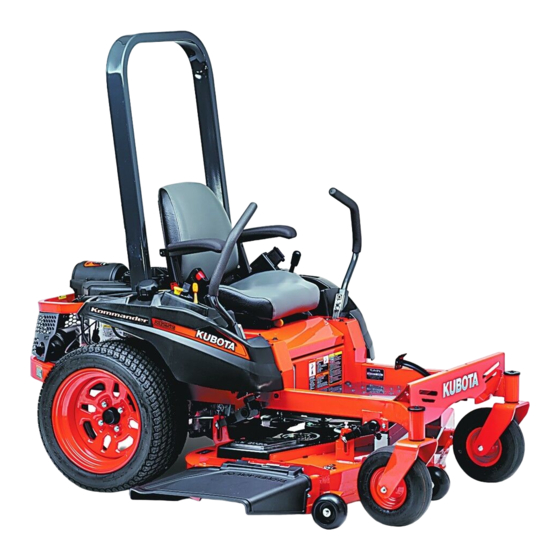
Summary of Contents for Kubota Z122E-AU
- Page 1 OPERATOR'S MANUAL MODELS Z122E-AU Z121S-AU Z125E-AU Z125S-AU · · · 1BDABDYAP0010 English (AUS) AS . B . 1 - 1 . - . AK Code No. K3014-7123-1 READ AND SAVE THIS MANUAL © PRINTED IN U.S.A. KUBOTA Corporation 2014...
- Page 2 KUBOTA Corporation is ··· Revolutions Per Minute Society of Automotive Engineers Since its inception in 1890, KUBOTA Corporation has grown to rank as one of the major firms in Japan. To achieve this status, the company has through the years...
- Page 3 FOREWORD You are now the proud owner of a KUBOTA ZERO TURN MOWER. This machine is a product of KUBOTA's quality engineering and manufacturing. It is made of excellent materials and under a rigid quality control system. It will give you long, satisfactory service.
-
Page 4: Table Of Contents
CONTENTS SAFE OPERATION .................... SERVICING OF MACHINE ..................1 SPECIFICATIONS....................... 3 IMPLEMENT LIMITATIONS ..................5 INSTRUMENT PANEL AND CONTROLS..............6 MOWER MOUNTING ....................8 MOUNTING THE MOWER DECK ................8 ADJUSTING THE MOWER ..................8 DISMOUNTING THE MOWER DECK ..............8 OPERATING THE ENGINE.................. - Page 5 CONTENTS ADJUSTING CUTTING HEIGHT ................22 OPERATING MOWER................... 23 PTO Switch........................23 Starting ........................... 24 TIRES AND WHEELS ....................25 TIRES........................25 Inflation Pressure......................25 WHEELS ........................ 25 Remove and Install Front Caster Wheels ............... 26 MAINTENANCE......................27 SERVICE INTERVALS ..................27 LUBRICANTS AND FUEL..................
- Page 6 CONTENTS Checking Engine Valve Clearance (Z121S, Z125S)............54 EVERY AFTER 500 HOURS ................. 55 Cleaning Combustion Chamber..................55 EVERY 1 YEAR ..................... 55 Replacing Precleaner Element (Except Z125E) ............. 55 Replacing Air Cleaner Element (Z122E, Z125E) ............55 Replacing Air Cleaner Element (Z121S, Z125S) ............55 Changing Engine Oil (Z122E, Z125E) ................
- Page 8 8. Do not operate the machine or any attachments while machine itself. under the influence of alcohol, medication, controlled 4. KUBOTA recommends the use of a Roll Over substances or when fatigued. Protective Structures (ROPS) and seat belt in almost 9.
- Page 9 Catcher. Your view to the rear is restricted. result in personal injury. 7. When working in groups, always let others know what 18. Use only implements approved by KUBOTA. Use you are doing ahead of time. proper ballast to front or rear of machine to reduce the 8.
- Page 10 SAFE OPERATION C Operators, age 60 years and above C Stopping Data indicates that operators, age 60 years and above, 1. Park the machine on level ground. 2. Make sure that the machine and all attachments have are involved in a large percentage of machine-related come to a complete stop before dismounting.
- Page 11 8. Do not use or charge the refillable type battery if the 24. See your local Recycling Center or KUBOTA Dealer to fluid level is below the LOWER (lower limit level) mark. learn how to recycle or get rid of waste products.
- Page 12 SAFE OPERATION 5. DANGER, WARNING AND CAUTION LABELS...
- Page 13 SAFE OPERATION...
- Page 14 SAFE OPERATION...
- Page 15 2. Clean danger, warning and caution labels with soap and water, and dry with a soft cloth. 3. Replace damaged or missing danger, warning and caution labels with new labels from your local KUBOTA Dealer. 4. If a component with danger, warning and caution label(s) affixed is replaced with new part, make sure new label(s) is (are) attached in the same location(s) as the replaced component.
-
Page 16: Safe Operation
When in need of parts or major service, be sure to see your KUBOTA Dealer. When in need of parts, be prepared to give your dealer the serial number of the machine, ROPS, engine and mower. - Page 17 SERVICING OF MACHINE [Z121S, Z125S] (1) Engine serial No. (1) Mower identification plate (2) Mower serial No. (1) ROPS serial No.
-
Page 18: Specifications
SPECIFICATIONS SPECIFICATIONS Model Z122E-AU Z121S-AU Z125E-AU Z125S-AU Model GH731V-1 GH736V GH733V-1 GH750V Max. engine power kW (HP) 16.4 (22) *1*2 15.7 (21) *1*3 18.6 (25) *1*2 18.6 (25) *1*3 (Gross) Type Air-cooled gasoline engine Number of cylinders 2 (V-Twin) 79 x 73... - Page 19 Kohler reserves the right to change product specifications, design, and standard equipment without notice and without incurring obligation. *4: Oil amount when the oil level is at the upper level. Model RCK48P-124Z RCK54P-127ZA Suitable machine Z122E-AU, Z121S-AU Z125E-AU, Z125S-AU Mounting method Parallel linkage Adjustment of cutting height Dial gauge Cutting width mm (in.)
-
Page 20: Implement Limitations
Use with implements which are not sold or approved by KUBOTA and which exceed the maximum specifications listed below, or which are otherwise unfit for use with the KUBOTA Machine may result in malfunctions or failures of the machine, damage to other property and injury to the operator or others. [Any malfunctions or failures of the machine resulting from use with improper implements are not covered by the warranty.]... -
Page 21: Instrument Panel And Controls
INSTRUMENT PANEL AND CONTROLS INSTRUMENT PANEL AND CONTROLS ILLUSTRATED CONTENTS ILLUSTRATED CONTENTS Parking brake lever......9, 17 Cutting height control dial..... Motion control lever......9, 18 Key switch..........Seat belt..........(10) Hour meter........... Cup holder..........(11) PTO switch........... Operator's seat........(12) Throttle lever........ -
Page 22: Illustrated Contents
INSTRUMENT PANEL AND CONTROLS ILLUSTRATED CONTENTS (1) Anti-scalp roller (Front, bolt shift type)..22... -
Page 23: Mower Mounting
MOWER MOUNTING MOWER MOUNTING MOUNTING THE MOWER DECK 7. Attach the PTO belt to the engine pulley. Refer the belt routing. To avoid serious injury: A Park the machine on a firm and level surface. A Apply the parking brake. A Stop the engine and remove the key. -
Page 24: Operating The Engine
OPERATING THE ENGINE OPERATING THE ENGINE STARTING THE ENGINE To avoid serious injury: 1. Sit on the operator's seat. A Read and understand "SAFE OPERATION" in the front of this manual. 2. Apply the parking brake. A Read and understand the danger, warning and caution labels located on the machine. -
Page 25: Motion Control Lever
OPERATING THE ENGINE 3. Make sure that the PTO switch is in the 5. Set the throttle lever as follows. "DISENGAGED" (OFF) position. A If the engine is cold: Place the throttle lever to the "CHOKE" position. A If the engine is warm: Place the throttle lever midway between the "SLOW"... -
Page 26: Throttle Lever
Do not after the engine starts and warms up. jump start using another battery. Consult your local KUBOTA dealer. The engine/equipment may be operated during the warm- A Do not turn the key switch to the "START" position up period, but it may be necessary to leave the choke while the engine is running. -
Page 27: Check During Operating
OPERATING THE ENGINE CHECK DURING OPERATING BHour Meter While operating, make the following checks to see that all This meter gives readings for the number of hours the the parts are functioning normally. engine has been running. BImmediately Stop the Engine if: A The engine suddenly slows down or accelerates. -
Page 28: Warming Up
A If noises are heard after the hydraulic control lever has been activated and the implement is lifting, the hydraulic mechanism is not adjusted properly. Unless corrected, the unit will be damaged. Contact your local KUBOTA Dealer for adjustment. (1) Dead battery Connect cables in numerical order. (2) Jumper cables... -
Page 29: Stopping The Engine
OPERATING THE ENGINE STOPPING THE ENGINE A Use of a higher voltage source on a machine could result in severe damage to the machine electrical 1. After slowing the engine to half speed, turn the key system. switch to the "OFF" position. Use only matching voltage source when "jump- 2. -
Page 30: Operating The Machine
OPERATING THE MACHINE OPERATING THE MACHINE OPERATING NEW MACHINE How a new machine is operated and maintained will To avoid serious injury or death: determine the life of the machine. A The machine relies upon the engine driven A new machine just off the factory production line has transmission for speed, direction, and motion been tested, but the various parts are not accustomed to control. -
Page 31: Starting
OPERATING THE MACHINE STARTING BSeat Belt 1. Adjust the operator's position and apply the seat belt. To avoid serious injury or death: A Always use the seat belt when the ROPS is BOperator's Seat installed. A Do not use the seat belt if a foldable ROPS is down or there is no ROPS. -
Page 32: Mower Lift Pedal
OPERATING THE MACHINE 3. Start the engine. 5. Accelerate the engine. See "OPERATING THE ENGINE" section. BThrottle Lever Moving the throttle lever backward decreases the engine speed and moving it forward increases the engine speed. 4. Raise the implement. BMower Lift Pedal The mower lift pedal is used to raise and lower the mower deck. -
Page 33: Motion Control Lever
A The motion control linkages are adjustable. If adjustment is required, see "ADJUSTMENT" section. We recommend you to contact your local KUBOTA Dealer. (1) Motion control levers (A) "NEUTRAL LOCK" position (B) "NEUTRAL" position (held by hand) - Page 34 OPERATING THE MACHINE FORWARD: GENERAL RIGHT TURN: A Push both motion control levers forward equally at the A Push left motion control lever further forward than the same time. For forward travel in a straight line. right motion control lever. For forward travel to the right.
-
Page 35: Stopping
OPERATING THE MACHINE STOPPING PARKING TO LOCK: Place the parking brake lever in the "ENGAGED" position. To avoid serious injury: TO UNLOCK: A Park the machine on level ground. Place the parking brake lever in the "DISENGAGED" If necessary to park on an incline, position. -
Page 36: Transporting
OPERATING THE MACHINE TRANSPORTING 1. Transport the machine on a trailer. A Turn the carburetor fuel valve to the "OFF" position. A Fasten the machine to the trailer. 2. Do not attempt to tow this machine, or damage to the transmission may result. -
Page 37: Operating The Mower
OPERATING THE MOWER OPERATING THE MOWER MAKING THE MOST OF YOUR MOWER ADJUSTING CUTTING HEIGHT 1. When using your mower for the first time, choose a smooth level area and cut in straight and slightly overlapping strips. To avoid serious injury or death: 2. -
Page 38: Operating Mower
OPERATING THE MOWER OPERATING MOWER 4. Lower the mower deck by pushing the mower lift pedal again. This lowers the mower deck from the "TRANSPORT" position "OPERATING" position. To avoid serious injury or death: 5. Adjust the anti-scalp rollers' height as recommended A Do not operate the mower without the below for normal operating condition. -
Page 39: Starting
OPERATING THE MOWER BStarting To avoid serious injury: A Engine components can get extremely hot from operation. To prevent severe burns, do not touch these areas while the engine is running, or immediately after it is turned off. Never operate the engine without heat shields or guards. -
Page 40: Tires And Wheels
TIRES AND WHEELS TIRES AND WHEELS TIRES WHEELS A When re-fitting a wheel, tighten the wheel bolt to the following torques then recheck after traveling 200 m To avoid serious injury: (200 yards) changing directions several times. A Do not attempt to mount a tire. This should be done by a qualified person with the proper equipment. -
Page 41: Remove And Install Front Caster Wheels
TIRES AND WHEELS BRemove and Install Front Caster Wheels C Removing 1. Park the machine on a firm and level surface. 2. Stop the engine and apply parking brake. 3. Lift the front of machine with a safe lifting device. 4. -
Page 42: Maintenance
MAINTENANCE MAINTENANCE SERVICE INTERVALS The following servicing tasks should be carried out on the machine at the stated running-time intervals. [Z122E, Z125E] Indication hour meter (Hr) Ref. Items Page After since every 50Hr Engine oil Change or every 1 year every 50Hr Engine oil filter Replace... - Page 43 *2 This maintenance should be done daily or more often in dusty condition than in normal conditions. Suggested cleaning interval is every 25 hours or every 1 year in normal conditions. *3 These items should be serviced by an authorized KUBOTA Dealer, unless the owner has the proper tools and is mechanically proficient.
- Page 44 *1 This maintenance should be done daily or more often in dusty condition than in normal conditions. *2 These items should be serviced by an authorized KUBOTA Dealer, unless the owner has the proper tools and is mechanically proficient.
-
Page 45: Lubricants And Fuel
See the Emissions Warranty Statement. 2. To ensure the best quality and reliability, use new KUBOTA Genuine parts or their equivalents for repair and replacement, whenever you have maintenance done. LUBRICANTS AND FUEL... -
Page 46: Periodic Service
PERIODIC SERVICE PERIODIC SERVICE HOW TO RAISE THE OPERATOR'S SEAT 2. Raise the operator's seat to the resting position. C Raise To avoid serious injury: A Fully raise the operator's seat. (To the resting position) Do not keep the seat halfway. 1. -
Page 47: Daily Check
Safety systems. If either of these do not operate (1) Engine oil port (A) "UPPER LEVEL" properly, contact your local KUBOTA (2) Oil level dipstick (B) "LOWER LEVEL" Dealer immediately. 5. When using a different brand or viscosity oil from the... -
Page 48: Checking Amount Of Fuel And Refueling
A Do not mix oil with gasoline. A Tighten the fuel cap until it clicks. A Do not use the fuel cap other than KUBOTA approved one. A Do not permit dirt or trash or water to get into the fuel system. -
Page 49: Checking And Cleaning Air Intake Screen
PERIODIC SERVICE BChecking and Cleaning Air Intake Screen BChecking Tire Pressure To avoid serious injury: To avoid serious injury: A Be sure to stop the engine and remove the key A Do not attempt to mount a tire on a rim. This before cleaning. -
Page 50: Checking Transaxle Fluid Level
PERIODIC SERVICE BChecking Transaxle Fluid Level BChecking Movable Parts 1. Park the machine on a flat surface, lower the If any of the movable parts, such as levers and pedals, is implement to the ground and shut off the engine and not smoothly moved because of rust or anything sticky, do remove the key. -
Page 51: Every 25 Hours
PERIODIC SERVICE EVERY 25 HOURS C Clean precleaner [Z122E] BCleaning Precleaner Element (Except Wash the precleaner every 25 hours of operation. Z125E) (more often under extremely dusty or dirty conditions.) 1. Loosen the air cleaner cover knobs and remove the air Check the air cleaner daily or before starting the cleaner cover. -
Page 52: Cleaning Air Cleaner Element (Z122E, Z125E)
PERIODIC SERVICE [Z121S, Z125S] Wash and reoil the precleaner every 25 hours of BCleaning Air Cleaner Element (Z122E, operation. (more often under extremely dusty or dirty Z125E) conditions.) Every 100 hours of operation or annually replace the 1. Unlatch the cover and remove the air cleaner cover. paper element. - Page 53 PERIODIC SERVICE 7. Reinstall the air cleaner cover and secure it with 2 6. Reinstall the air cleaner cover and secure it with 2 knobs. knobs. A Operating the engine with loose or damaged air A Operating the engine with loose or damaged air cleaner components could allow unfiltered air into the cleaner components could allow unfiltered air into the engine causing premature wear and failure.
-
Page 54: Every 50 Hours
A Sit on operator's seat for all tests except for Test 1. A If the engine cranks in Test 1 through 4, consult your local KUBOTA Dealer to have the unit checked before operation. A Check the following tests before operating the machine. -
Page 55: Checking Opc System
4. Stand up. (Do not get off the machine.) 5. The engine must shut off. A If the engine remains running in Test 1 through 2, consult your local KUBOTA Dealer to have the unit checked before operation. (1) Engine oil port (A) "UPPER LEVEL"... -
Page 56: Replacing Engine Oil Filter (Z122E, Z125E)
PERIODIC SERVICE [Z125E] BReplacing Engine Oil Filter (Z122E, Z125E) To avoid serious injury: A Engine oil is a toxic substance. Dispose of used properly. Contact your local authorities for approved disposal methods or possible recycling. To avoid serious injury: A Be sure to stop the engine and remove the key before changing the oil and the oil filter (1) Engine oil port (A) "UPPER LEVEL"... -
Page 57: Checking Muffler And Spark Arrester (If Equipped)
PERIODIC SERVICE BChecking Muffler and Spark Arrester (if equipped) Running engines produce heat. Engine parts, especially muffler, become extremely hot. Severe thermal burns can occur on contact. Combustible debris, such as leaves, grass, brush, etc. can catch fire. To avoid serious injury: A Allow muffler, engine cylinder and fins to cool before touching. -
Page 58: Every 100 Hours
PERIODIC SERVICE EVERY 100 HOURS 3. To check the oil level. Remove the dipstick, wipe it clean, insert it and draw it out again. Check to see that BChanging Engine Oil (Z121S, Z125S) the oil level is between the 2 marks. A Do not overfill. -
Page 59: Replacing Air Cleaner Element (Z121S, Z125S)
PERIODIC SERVICE A Operating the engine with loose or damaged air BReplacing Air Cleaner Element (Z121S, cleaner components could allow unfiltered air into the Z125S) engine causing premature wear and failure. Every 100 hours of operation or annually replace the paper element. -
Page 60: Checking Spark Plug
PERIODIC SERVICE [Z125E] BChecking Spark Plug Every 100 hours of operation check the spark plug condition and gap. Annually replace the spark plug. 1. Remove the spark plug wire from spark plug. 2. Use a spark plug wrench to remove plug. A This engine is equipped with resistor-type spark plug. -
Page 61: Checking Fuel Lines
PERIODIC SERVICE [Z121S, Z125S] BChecking Fuel Lines To avoid serious injury: A Be sure to stop the engine and remove the key when attempting to make the following checks and changes. A Never fail to check the fuel lines periodically. The fuel lines are subject to wear and aging. - Page 62 PERIODIC SERVICE (1) Fuel line (1) Fuel line (A) Muffler (2) Pipe clamp (2) Pipe clamp (B) Carburetor (3) Fuel filter (1) Fuel line (2) Pipe clamp (1) Fuel line (2) Pipe clamp (3) Fuel pump...
-
Page 63: Battery Condition
PERIODIC SERVICE A Mishandling the battery shortens the service life and BBattery Condition adds to maintenance costs. The original battery is maintenance free, but needs some servicing. If the battery is weak, the engine will be difficult to start To avoid the possibility of battery explosion: and the lights will be dim. -
Page 64: Adjusting Throttle Cable
PERIODIC SERVICE BAdjusting Throttle Cable [Z122E, Z125E] 1. Move the throttle lever to the "FAST" position. (1) Battery (+): Positive terminal (2) Ground cable (-): Negative terminal 1. To slow charge the battery, connect the battery positive terminal to the charger positive terminal and the negative to the negative, then charge for at least 1 (1) Throttle lever hour at 6.5 amperes. -
Page 65: Replacing Engine Oil Filter (Z121S, Z125S)
PERIODIC SERVICE [Z121S, Z125S] 1. Move the throttle lever to the "FAST" position. BReplacing Engine Oil Filter (Z121S, Z125S) To avoid serious injury: A Engine oil is a toxic substance. Dispose of used properly. Contact your local authorities for approved disposal methods or possible recycling. -
Page 66: Every 200 Hours
PERIODIC SERVICE EVERY 200 HOURS BChecking Hydraulic Hose To avoid serious injury: A Be sure to stop the engine, remove the key, and relieve pressure before checking and replacing the hydraulic hose. A Allow the transmission case to cool down sufficiently;... -
Page 67: Every 400 Hours
PERIODIC SERVICE EVERY 400 HOURS BReplacing Transaxle Oil Filter Cartridge To avoid serious injury: A Park the machine on a firm and level surface. A Apply the parking brake. A Be sure to stop the engine and remove the key before changing or checking the oil. -
Page 68: Changing Transaxle Fluid
PERIODIC SERVICE C Purging Procedures Due to the effects air has on efficiency in hydrostatic drive applications, it is critical that it is purged from the system. Air creates inefficiency because its compression and expansion rate is higher than that of the oil approved for use in hydrostatic drive systems. -
Page 69: Every 500 Hours
1. Locate the inspection windows on the clutch. 2. Place a 0.4 mm (0.015 in.) feeler gauge in the slot between the rotor and the armature. (See the figure.) BChecking Engine Valve Clearance (Z121S, Z125S) Consult your local KUBOTA Dealer for this service. - Page 70 EVERY 2 YEARS BCleaning Combustion Chamber BReplacing Hydraulic Hose If you do not have the proper tools and/or are not Consult your local KUBOTA Dealer for this service. mechanically proficient, consult your local KUBOTA Dealer for this service. BReplacing Fuel Lines Consult your local KUBOTA Dealer for this service.
- Page 71 PERIODIC SERVICE SERVICE AS REQUIRED BChecking and Replacing Blade BReplacing Fuses Replacement of the fuse 1. Raise the operator's seat. To avoid serious injury: 2. Remove the blown fuse. A Be sure to stop the engine and remove the key. 3.
- Page 72 PERIODIC SERVICE A To prolong the service life of the blades, reposition them as shown in the figure below periodically. (1) Block (A) "LOOSEN" 3. To sharpen the blades yourself, clamp the blade (1) LH blade securely in a vise. (2) Center blade Use a large mill file and file along the original bevel (3) RH blade...
- Page 73 PERIODIC SERVICE BMower Belt Replacement 1. Remove the mower deck from the machine according to the procedure "DISMOUNTING THE MOWER DECK". 2. Remove the left and right hand shield from the mower deck. 3. Remove the tension pulley, and remove the belt. 4.
- Page 74 (2.4 to 2.8 kgf-m, adjustments correctly and safely, please 17.4 to 20.2 lbf-ft) contact your local KUBOTA Dealer. 7. Adjust the other side "HST NEUTRAL" equally. A Right and left motion control levers can be adjusted 8. After adjustment, make sure to stop the engine independently.
- Page 75 ADJUSTMENT [LH] BMAXIMUM SPEED (FORWARD) Consult your local KUBOTA Dealer for this service. BMOTION CONTROL LEVER ALIGNMENT C Check the alignment Check the gap and space between the levers, at the maximum forward position. Gap: 0 to 2 mm Recommendation (0 to 0.08 in.)
- Page 76 ADJUSTMENT MOWER DECK LEVEL C Aligning the control levers 1. Stop the engine and apply the parking brake. BANTI-SCALP ROLLERS Lever position (High or Low) 2. Remove the bolts and select the motion control lever position, high or low. To avoid serious injury: 3.
- Page 77 ADJUSTMENT BLEVEL MOWER DECK (Side-to-Side) To avoid serious injury: A Park the machine on a firm and level surface. A Apply the parking brake. A Disengage PTO (OFF). A Stop the engine and remove the key while checking or adjusting the level of the mower deck.
- Page 78 ADJUSTMENT Less than 6 mm (1/4 in.) BLEVEL MOWER DECK (Front-to-Rear) Front-to-Rear Front side must be lower adjustment than Rear side. To avoid serious injury: C Adjusting level (Front-to-Rear) A Park the machine on a firm and level surface. 1. Raise up the mower deck to the transport position. A Engage the parking brake.
- Page 79 ADJUSTMENT GENERAL TORQUE SPECIFICATION American standard cap screws Metric cap screws with UNC or UNF threads GR.5 GR.8 Class 8.8 Class 10.9 SAE grade No. Property class (lbf-ft) 8 - 9.6 12 - 14.4 (lbf-ft) 7.2 - 8.3 (N-m) 10.7 - 12.9 16.1 - 19.3 (N-m) 9.81 - 11.3...
- Page 80 ADJUSTMENT TIGHTENING TORQUE CHART Thread Hexa-Bolt No mark size Head size lbf-ft kgf-m lbf-ft kgf-m d (mm) B (mm) 13.0 - 15.2 17.8 - 20.6 1.9 - 2.1 17.5 - 20.3 23.5 - 27.5 2.4 - 2.8 12 or 13 (14.1 1.1) (19.2...
- Page 81 STORAGE STORAGE REMOVING THE MOWER FROM STORAGE To avoid serious injury: 1. Check the tire inflation pressure and adjust as A To reduce fire hazards, allow the engine and required. exhaust system to cool before storing the 2. Install the battery. Before installing the battery, be sure machine in an enclosed space or near it is fully charged.
- Page 82 A Replace fuel and the fuel filter. (Fuel quality is poor.) A Water or dirt in the fuel system. A Replace fuel and see your Kubota dealer. A Fuel hose or fuel filter clogged or A Clean or replace fuel lines, and see damaged.
- Page 83 A Spark plug defective. A Adjust the spark plug gap or replace it. A Faulty spark plug. A Replace the spark plug. A Carburetion problem. A See your Kubota dealer. If you have any questions, contact your local KUBOTA Dealer.
- Page 84 A Charging system A Contact your local trouble. KUBOTA Dealer. If you have any questions, contact your local KUBOTA Dealer. MACHINE TROUBLESHOOTING Symptom (If) Cause Remedy Machine operation is not A Hydrostatic transaxle fluid A Replenish oil.
- Page 85 MOWER TROUBLESHOOTING Symptom (If) Cause Remedy Blade does not rotate. A PTO system is not normal: A See your Kubota Dealer. PTO system malfunctioning. A PTO system is normal: A Replace. Broken mower belt. Mower belt slipping. A Weaken tension spring.
- Page 86 A Ground speed too fast. A Slow down. A Debris wrapped around mower spindles. A Clean mower. A Front of deck too low. A Adjust mower deck. (See "MOWER DECK LEVEL" "ADJUSTMENT" section.) If you have any questions, contact your local KUBOTA Dealer.
- Page 87 INDEX INDEX Mower Belt Replacement ......58 Air Cleaner Element (Z121S, Z125S).....44 Mower Lift Pedal ..........17 Air Cleaner Element (Z121S, Z125S).....55 Muffler and Spark Arrester (if equipped) ..42 Air Cleaner Element (Z122E, Z125E).....37 Muffler and Spark Arrester (if equipped) ..55 Air Cleaner Element (Z122E, Z125E).....43 OPC System ..........
Need help?
Do you have a question about the Z122E-AU and is the answer not in the manual?
Questions and answers