Table of Contents
Advertisement
Thank you for purchasing LS Variable Frequency Drives!
Always follow safety instructions to prevent accidents and potential hazards
from occurring.
In this manual, safety messages are classified as follows:
WARNING Improper operation may result in serious personal injury or
CAUTION Improper operation may result in slight to medium personal
injury or property damage.
Throughout this manual we use the following two illustrations to make you
aware of safety considerations:
Identifies potential hazards under certain conditions. Read the message
and follow the instructions carefully.
Identifies shock hazards under certain conditions. Particular attention
should be directed because dangerous voltage may be present.
Keep operating instructions handy for quick reference.
Read this manual carefully to maximize the performance of SV-iC5 series
inverter and ensure its safe use.
Do not remove the cover while power is applied or the unit is in operation.
Otherwise, electric shock could occur.
Do not run the inverter with the front cover removed.
Otherwise, you may get an electric shock due to high voltage terminals or
charged capacitor exposure.
Do not remove the cover except for periodic inspections or wiring, even if
the input power is not applied.
Otherwise, you may access the charged circuits and get an electric shock.
Wiring and periodic inspections should be performed at least 10 minutes
after disconnecting the input power and after checking the DC link
voltage is discharged with a meter (below DC 30V).
Otherwise, you may get an electric shock.
Operate the switches with dry hands.
Otherwise, you may get an electric shock.
SAFETY INSTRUCTIONS
death.
WARNING
Important User Information
i
Advertisement
Table of Contents

Related Manuals for LSIS SV008iC5-1F


Summary of Contents for LSIS SV008iC5-1F
- Page 1 Important User Information Thank you for purchasing LS Variable Frequency Drives! SAFETY INSTRUCTIONS Always follow safety instructions to prevent accidents and potential hazards from occurring. In this manual, safety messages are classified as follows: WARNING Improper operation may result in serious personal injury or death.
- Page 2 Important User Information Do not use the cable when its insulating tube is damaged. Otherwise, you may get an electric shock. Do not subject the cables to scratches, excessive stress, heavy loads or pinching. Otherwise, you may get an electric shock. CAUTION ...
- Page 3 Important User Information -10 ~ 50℃ (non-freezing), Ambient 40°C for Surrounding models SV004iC5-1, SV004iC5-1F, SV008iC5- temperature 1, and SV008iC5-1F (UL 508C) Relative 90% RH or less (non-condensing) humidity Environment Storage - 20 ~ 65 ℃ temperature Protected from corrosive gas, combustible gas,...
- Page 4 Important User Information In case of input voltage unbalance, install AC reactor. Power Factor capacitors and generators may become overheated and damaged due to potential high frequency noise transmitted from inverter. Before operating unit and prior to user programming, reset user parameters to default settings.
- Page 5 Manual outline Important User Information The purpose of this manual is to provide the user with the necessary information to install, program, start up and maintain the SV-iC5 series inverter. To assure successful installation and operation, the material presented must be thoroughly read and understood before proceeding.
-
Page 6: Table Of Contents
Table of Contents Table of Contents Basic Information and Precautions ..............1-1 Important Precautions ....................1-1 Product Details ....................... 1-2 Removal and Reinstallation ....................1-3 Installation ......................2-1 Installation Precautions ....................2-1 Dimensions ........................2-3 Wiring........................ 3-1 Terminal Wiring ......................3-1 Specifications for Power Terminal Block Wiring .............. - Page 7 Table of Contents Function List ...................... 7-1 Drive Group ........................7-1 Function Group 1 ......................7-3 Function Group 2 ......................7-8 I/O Group ........................7-16 Troubleshooting and Maintenance ..............8-1 Protective Functions ......................8-1 Fault Remedy .........................8-3 Precautions for Maintenance and Inspection ...............8-5 Check Points ........................8-5 Part Replacements ......................8-6 Specifications ....................
-
Page 9: Basic Information And Precautions
1. Basic information and precautions 1. Basic Information and Precautions 1.1 Important Precautions Inspect the inverter for any damage that may have occurred Unpacking during shipping. To verify the inverter unit is the correct one for the application you need, check the inverter type, output ratings inspection on the nameplate and the inverter is intact. -
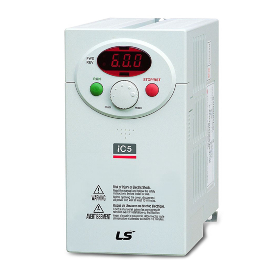
Page 10: Product Details
1. Basic information and precautions 1.2 Product Details 1.2.1 Appearance Keypad Status LED Potentiometer Display Window STOP/RST Front Cover: Button Remove it when wiring and changing Body slot: When front parameter setting. cover is pulled back till this line and lifted up, Bottom Cover: it can be removed Remove it when... -
Page 11: Removal And Reinstallation
1. Basic information and precautions 1.3 Removal and Reinstallation 1.3.1 Removal of the front cover To change parameter setting: Press the pattern with a finger slightly as 1) and push it downward as 2). Then 4-way button will appear. Use this button for parameter setting and changing the value. - Page 12 1. Basic information and precautions Removal for wiring input power and terminals: After removing the front cover, lift the bottom cover up to disconnect. ☞Note: Input Power Terminals name is labeled here. To access control terminals: after finishing power terminal wiring, ...
-
Page 13: Installation
Install in a location where temperature is within the permissible range (-10~50°C). Maximum Surrounding Air Temperature is 50°C. Models SV004iC5-1, SV004iC5- 1F, SV008iC5-1, and SV008iC5-1F can be used in Ambient 40°C. (UL 508C) <Ambient Temp Checking Location> The inverter will be very hot during operation. Install it on a non-combustible surface. - Page 14 2. Installation When two or more inverters are installed or a ventilation fan is mounted in inverter panel, the inverters and ventilation fan must be installed in proper positions with extreme care taken to keep the ambient temperature of the inverters below the permissible value.
-
Page 15: Dimensions
2. Installation 2.2 Dimensions 0.4, 0.75 kW (1/2~1 HP) Dimension 004iC5-1 004iC5-1F 008iC5-1 008iC5-1F Weight 0.87 0.95 0.89 0.97 (Kg) - Page 16 2. Installation 1.5, 2.2 kW (2~3HP) Dimension 015iC5-1 015iC5-1F 022iC5-1 022iC5-1F Weight 1.79 1.94 1.85 (Kg)
-
Page 17: Wiring
3. Wiring 3. Wiring 3.1 Terminal Wiring P4 P5 VR V1 CM I AM 30A 30B 30C MO EXTG P24 P1 P2 CM P3 Termi- Features FX : Forward run Multi- RX : Reverse run Function BX : Emergency stop input terminal RST : Fault reset... -
Page 18: Specifications For Power Terminal Block Wiring
3. Wiring 3.2 Specifications for Power Terminal Block Wiring SV004iC5-1 SV008iC5-1 SV015iC5-1 SV022iC5-1 L1 L2 P P1 N P P N U V W Input wire size 3.5mm 3.5mm Output wire 3.5mm 3.5mm Ground Wire 3.5mm 3.5mm , 3.5 φ , 3.5 φ... - Page 19 3. Wiring WARNING Use the Type 3 grounding method (Ground impedance: Below 100ohm). Use the dedicated ground terminal to ground the inverter. Do not use the screw in the case or chassis, etc for grounding. Dedicated Dedicated Ground Ground Terminal Terminal ☞...
-
Page 20: I/O Terminal Block Specification
3. Wiring I/O terminal Block Specification Torque Terminal Terminal Description Wire size Note (Nm) P1/P2/P3 Multi-function input T/M 22 AWG, 0.3 mm /P4/P5 P1-P5 Common Terminal for 22 AWG, 0.3 mm P1-P5, AM, P24 Max. output voltage: 12V 12V power supply for 22 AWG, 0.3 mm Max. -
Page 21: Pnp/Npn Selection And Connector For Communication Option
3. Wiring PNP/NPN Selection and Connector for Communication Option 1. When using P24 [NPN] Resistor Resistor Resistor 2. When using 24V external power supply [PNP] Resistor Resistor Resistor 2. Communication Option Card Connector: Install Communication option ☞Note: MODBUS RTU option card is available for SV-iC5. Refer to MODBUS RTU option card manual for more details. - Page 22 3. Wiring...
-
Page 23: Basic Configuration
4. Basic configuration 4. Basic Configuration Connection of Peripheral Devices to the Inverter The following devices are required to operate the inverter. Proper peripheral devices must be selected and correct connections made to ensure proper operation. An incorrectly applied or installed inverter can result in system malfunction or reduction in product life as well as component damage. -
Page 24: Recommendable Ac/Dc Reactor
4. Basic configuration 4.2 Recommended MCCB, Earth Leakage Circuit Breaker (ELB) and Magnetic Contactor Specification Magnetic Model MCCB Contactor 004iC5-1, 1F MC-6a 008iC5-1, 1F MC-9a, MC-9b ABS33c, UTE100 EBS33c 015iC5-1, 1F MC-18a, MC-18b 022iC5-1, 1F MC-22b 4.3 Recommendable AC/DC Reactor Model AC input fuse AC reactor... -
Page 25: Programming Keypad
5. Programming Keypad 5. Programming Keypad Keypad Features Display FWD/REV LED 7-Segment LED Buttons RUN STOP/RST 4-WAY BUTTON Potentiometer Display Lit during forward run Blinks when a fault occurs Lit during reverse run 7-Segment Displays operation status and parameter information (LED Display) Keys... -
Page 26: Alpha-Numeric View On The Led Keypad
5. Programming Keypad 5.2 Alpha-numeric View on the LED Keypad... -
Page 27: Moving To Other Groups
5. Programming Keypad 5.3 Moving to Other Groups There are 4 different parameter groups in SV-iC5 series as shown below. Drive group Function group 1 Function group 2 I/O group Basic parameters necessary for the inverter to run. Parameters Drive group such as Target frequency, Accel / Decel time are settable. - Page 28 5. Programming Keypad How to move to other groups at the 1 code of each group. -. The 1 code in Drive group “0.0” will be displayed when AC input power is applied. -. Press the right arrow () key once to go to Function group 1. -.
-
Page 29: How To Change The Codes In A Group
5. Programming Keypad 5.4 How to change the codes in a group Code change in Drive group -. In the 1 code in Drive group “0.0”, press the Up () key once. -. The 2 code in Drive group “ACC”... - Page 30 5. Programming Keypad For changing code from any codes other than F 0 When moving from F 1 to F 15 in Function group 1. -. In F 1, continue pressing the Up () key until F15 is displayed. Moving been complete.
-
Page 31: Parameter Setting Method
5. Programming Keypad Parameter Setting Method Changing parameter value in Drive group When changing ACC time from 5.0 sec to 16.0 Drive group -. In the first code “0.0”, press the Up () key once to go to the second code. -. - Page 32 5. Programming Keypad When changing run frequency to 30.05 Hz in Drive group Drive group -. In “0.0”, press the Prog / Ent () key once. -. The second 0 in 0.0 is active. -. Press the Right () key once to move the cursor to the right.
- Page 33 5. Programming Keypad Changing parameter values in Function 1, 2 and I/O group When changing the parameter value of F 27 from 2 to 5 Function group 1 -. In F0, press the Prog / Ent () key once. -.
-
Page 34: Monitoring Of Operation Status
5. Programming Keypad Monitoring of Operation Status Monitoring output current in Drive group Drive group -. In [0.0], continue pressing the Up () or Down () key until [Cur] is displayed. -. Monitoring output current is provided in this parameter. -. - Page 35 5. Programming Keypad How to monitor Motor rpm in Drive group when the motor is rotating in 1730 rpm. Drive group -. Present run frequency can be monitored in the first code of Function group 1. The preset frequency is 57.6Hz. -.
- Page 36 5. Programming Keypad How to monitor fault condition in Drive group. During Over- Accel current Current Trip Frequency Drive group STOP/RST -. This message appears when an Over-current fault occurs. -. Press the Prog / Ent () key once. -. The run frequency at the time of fault (30.0) is displayed. -.
- Page 37 5. Programming Keypad Parameter initialize How to initialize parameters of all four groups in H93 Function group 2 -. In H0, press the Prog / Ent () key once. -. Code number of H0 is displayed. -. Increase the value to 3 by pressing the Up () key. -.
- Page 38 5. Programming Keypad 5-14...
-
Page 39: Basic Operation
6. Basic Operation 6. Basic Operation 6.1 Frequency Setting and Basic Operation ☞ Caution : The following instructions are given based on the fact that all parameters are set to factory defaults. Results could be different if parameter values are changed. In this case, initialize parameter values back to factory defaults and follow the instructions below. - Page 40 6. Basic Operation Frequency Setting via potentiometer and operating via terminals -. Apply AC input power to the inverter. -. When 0.0 appears Press the Up () key four times. -. Frq is displayed. Frequency setting mode is selectable. -. Press the Prog / Ent () key once. -.
- Page 41 6. Basic Operation Frequency setting via potentiometer and operating via the Run key -. Apply AC input power to the inverter. -. When 0.0 is displayed, press the Up () key three times. -. drv is displayed. Operating method is selectable. -.
- Page 42 6. Basic Operation...
-
Page 43: Function List
7. Function List 7. Function List * The number of page is for User’s manual uploaded at LSIS website. You can download the User’s manual which is described detailed function of parameter from website. (http://www.lsis.biz) 7.1 Drive Group Parameter Min/Max... - Page 44 7. Function List Parameter Min/Max Factory Adjustable Description Page display name range defaults during run Setting via potentiometer on the keypad + I terminal Setting via V1 + I terminal Setting via potentiometer on the keypad + V1 terminal Modbus-RTU Communication ...
-
Page 45: Function Group 1
7. Function List 7.2 Function Group 1 Parameter Min/Max Factory Adjustable Description Page display name range defaults during run [Jump 0/60 This parameter sets the code] parameter code number to jump. Fwd and rev run enable [Forward/ Reverse Forward run disable run disable] Reverse run disable [Accel... - Page 46 7. Function List Parameter Min/Max Factory Adjustable Description Page display name range defaults during run [Jog 0/400 This parameter sets the 10.0 frequency] [Hz] frequency for Jog operation. It cannot be set above F21 – [Max frequency]. [Max 40/400 * This parameter sets the...
- Page 47 7. Function List Parameter Min/Max Factory Adjustable Description Page display name range defaults during run [Torque This parameter sets the boost in amount of torque boost reverse applied to a motor during direction] reverse run. It is set as a percent of Max output voltage [V/F pattern] 0/2 0 {Linear}...
- Page 48 7. Function List Parameter Min/Max Factory Adjustable Description Page display name range defaults during run [Electronic 50/200 This parameter sets max thermal current capable of flowing to level for 1 the motor continuously for 1 minute] minute. value percentage of H33 –...
- Page 49 7. Function List Parameter Min/Max Factory Adjustable Description Page display name range defaults during run [Stall This parameter stops accelerating prevention during acceleration, decelerating select] during constant speed run and stops decelerating during deceleration. During During During Decelerati- constant Acceleratio speed Bit 2...
-
Page 50: Function Group 2
7. Function List 7.3 Function Group 2 Parameter Min/Max Factory Adjustable Description Page display name range defaults during run [Jump code] 1/95 This parameter sets the code number to jump. [Fault This parameter stores history 1] information on the types of faults, the frequency, [Fault the current and the... - Page 51 7. Function List Parameter Min/Max Factory Adjustable Description Page display name range defaults during run [Skip 25.0 frequency high limit 2] [Skip 30.0 frequency low limit 3] [Skip 35.0 frequency high limit 3] S-Curve 1/100 Set the speed accel/decel reference value to form a start side curve at the start during...
- Page 52 7. Function List Parameter Min/Max Factory Adjustable Description Page display name range defaults during run [Speed 0/15 This parameter is active to prevent any Search possible fault when the inverter outputs its Select] voltage to the running motor. 2.Restart 3.Operation 4.Normal H20-...
- Page 53 7. Function List Parameter Min/Max Factory Adjustable Description Page display Name Range defaults during run This parameter sets the [Number of 0/10 number of restart tries after Auto a fault occurs. Restart try] Auto Restart deactivated fault outnumbers the restart tries. ...
- Page 54 7. Function List Parameter Min/Max Factory Adjustable Description Page display Name Range defaults during run [Load Select one of the inertia rate] following according to motor inertia. Less than 10 times that of motor inertia About 10 times that of motor inertia More than 10 times that of motor inertia...
- Page 55 7. Function List Parameter Min/Max Factory Adjustable Description Page display Name Range defaults during run This parameter sets [P gain for 0/999.9 300.0 the gains for the PID controller. controller] [Integral 0.1/32.0 time for PID [sec] controller (I gain)] Differential 0.0 /30.0 time for PID...
- Page 56 7. Function List Parameter Min/Max Factory Adjustable Description Page display Name Range defaults during run Multi-Step frequency 2 Multi-Step frequency 3 Output current Motor rpm 10 Inverter DC link voltage 11 User display select 12 Fault display Direction of motor rotation select ...
- Page 57 7. Function List motor 30/150 stall prevention level] motor 50/200 Electronic thermal level for 1 min] motor Electronic thermal level for continuous] motor 0.1/20 rated current] [Parameter This parameter is initialize] used to initialize parameters back to the factory default values. All parameter groups are initialized to factory default value.
-
Page 58: I/O Group
7. Function List 7.4 I/O Group Parameter Min/Max Factory Adjustable Description Page display name range defaults during run [Jump code] 0/63 This parameter sets the code number to jump [Filter time 0/9999 This is used to adjust the constant for analog voltage input signal via V0 input]... - Page 59 7. Function List Parameter Min/Max Factory Adjustable Description Page display name range defaults during run [Frequency 0/400 Set the inverter output corresponding [Hz] minimum frequency at minimum to I 12] current of I input. [I input max 0/20 Set the Maximum Current of I current] [mA]...
- Page 60 7. Function List Parameter Min/Max Factory Adjustable Description Page display name range defaults during run Frequency decrease command (DOWN) 3-wire operation External trip: A Contact (EtA) External trip: B Contact (EtB) Exchange between operation and V/F operation Exchange between option and Inverter Analog Hold Accel/Decel Disable...
- Page 61 7. Function List Parameter Min/Max Factory Adjustable Description Page display name range defaults during run [Multi-Decel time 2] [Multi-Accel time 3] [Multi-Decel time 3] [Multi-Accel time 4] [Multi-Decel time 4] [Multi-Accel time 5] [Multi-Decel time 5] [Multi-Accel time 6] [Multi-Decel time 6] [Multi-Accel time 7]...
- Page 62 7. Function List Parameter Min/Max Factory Adjustable Description Page display name range defaults during run 10.0 [Frequency select] are set to 0-4. It cannot be set greater than detection bandwidth] F21 – [Max frequency]. [Multi-function 0/17 FDT-1 output terminal FDT-2 select] [Multi-function...
- Page 63 7. Function List [Inverter 1/32 This parameter is set when the station inverter uses RS485 number] communication. [Baud rate] Select the Baud rate of the RS485 1200 bps 2400 bps 4800 bps 9600 bps 19200 bps [Drive mode It is used when frequency select after command is given via V1 and I...
- Page 64 7. Function List 7-22...
-
Page 65: Troubleshooting And Maintenance
8. Troubleshooting and Maintenance 8. Troubleshooting and Maintenance Protective Functions WARNING When a fault occurs, the cause must be corrected before the fault can be cleared. If protective function keeps active, it could lead to reduction in product life and damage to the equipment. - Page 66 8. Troubleshooting and Maintenance Fault Display and information Keypad Protective Descriptions display functions The internal electronic thermal of the inverter determines the overheating of the motor. If the motor is overloaded the Electronic inverter turns off the output. The inverter cannot protect the Thermal motor when driving a motor having more than 4 poles or multi motors.
-
Page 67: Fault Remedy
8. Troubleshooting and Maintenance 8.2 Fault Remedy Protective Cause Remedy functions ☞ Caution: When an overcurrent fault occurs, operation must be started after the Overcurrent cause is removed to avoid damage to IGBT inside the inverter. Accel / Decel time is too short ... - Page 68 No frequency command is Check the wiring of V1 and I and applied to V1 and I. frequency reference level. Operating method when the frequency command is lost Contact your local LSIS sales representative. Parameter save error Hardware fault Communication Error...
-
Page 69: Precautions For Maintenance And Inspection
8. Troubleshooting and Maintenance Precautions for Maintenance and Inspection CAUTION Make sure to remove the input power while performing maintenance. Make sure to perform maintenance after checking the DC link capacitor has discharged. The bus capacitors in the inverter main circuit can still be charged even after the power is turned off. -
Page 70: Part Replacements
8. Troubleshooting and Maintenance Part Replacements The inverter consists of many electronic parts such as semiconductor devices. The following parts may deteriorate with age because of their structures or physical characteristics, leading to reduced performance or failure of the inverter. For preventive maintenance, the parts must be changed periodically. The parts replacement guidelines are indicated in the following table. -
Page 71: Specifications
9. Specifications 9. Specifications Technical Data Input and output ratings Model : SV xxx iC5 – 2x Max motor [HP] capacity [kW] 0.75 Capacity 0.95 [kVA] Output FLA [A] ratings Frequency 0 ~ 400 [Hz] Voltage Three Phase 200 ~ 230V Voltage Single Phase 200 ~ 230V (±10%) Input... - Page 72 9. Specifications Multi-function open collector Operating status Below DV 24V 50mA terminal and Fault output Output Multi-function (N.O., N.C.) (N.O., N.C.) Below relay terminal AC250V 0.3A, Below DC 30V 1A 0 ~ 10 Vdc : Frequency, Current, Voltage, DC link Analog output voltage selectable ...
-
Page 73: Temperature Derating Information
9. Specifications 9.2 Temperature Derating Information Load current VS Carrier frequency ▶ For 0.4kW, 0.8kW, 1.5kW inverter ▶ For 2.2kW inverter Load Load Current Current 100% 100% 1kHz 15kHz 1kHz 15kHz 8kHz Carrier freq. Carrier freq. ☞ Note : 1. - Page 74 9. Specifications...
-
Page 75: Declaration Of Conformity
ENV 50141:1993(EN 61000-4-6:1996) EN 61000-4-8:1993 EN 61000-4-11:1994 Type of Equipment: Inverter (Power Conversion Equipment) Model Name: SV - iC5 Series Trade Mark: LSIS Co., Ltd. Representative: LG International (Deutschland) GmbH Address: Lyoner Strasse 15, 60528, Frankfurt am Main, Germany Manufacturer: LSIS Co., Ltd. -
Page 76: Technical Standards Applied
DECLARATION OF CONFIRMITY TECHNICAL STANDARDS APPLIED The standards applied in order to comply with the essential requirements of the Directives 73/23/EEC "Electrical material intended to be used with certain limits of voltage" and 89/336/EEC "Electromagnetic Compatibility" are the following ones: “Electronic equipment for use in power installations”. -
Page 77: Emc Installation Guide
CE Mark Models Description Module1* Module 2** SV004iC5-1F AC Drive, 0.5HP, 220V, 1 phase SV008iC5-1F AC Drive, 1HP, 220V, 1 phase SV015iC5-1F AC Drive, 2HP, 220V, 1 phase SV022iC5-1F AC Drive, 3HP, 220V, 1 phase SV004iC5-1 AC Drive, 0.5HP, 220V, 1 phase 10120001681 10120001677... -
Page 78: Ul Marking
UL Marking UL Marking 1. SHORT CIRCUIT RATING The drive is suitable for use in a circuit capable of delivering not more than 5,000A RMS at the drive’s maximum rated voltage. (L’entraînement convient pour une utilisation dans un circuit capable de délivrer pas plus de 5,000A RMS à... - Page 79 EAC mark The EAC (EurAsian Conformity) mark is applied to the products before they are placed on the market of the Eurasian Customs Union member states. It indicates the compliance of the products with the following technical regulations and requirements of the Eurasian Customs Union: Technical Regulations of the Customs Union 004/2011 “On safety of low voltage equipment”...
- Page 80 Revision History Revision History Revision Date Remarks First Edition 2002. 12 S/W Version: 1.3 S/W version update 2003. 10 S/W Version: 1.5 S/W version update 2004. 5 S/W Version: 1.8 S/W version update 2005. 6 S/W Version: 1.9...
- Page 81 Note This product has been manufactured through the strict QC control and inspection of LSIS. Warranty period is 12 months after installation or 18 months after manufactured when the installation date is unidentified. However, the guarantee term may vary on the sales term.
Need help?
Do you have a question about the SV008iC5-1F and is the answer not in the manual?
Questions and answers