Table of Contents
Advertisement
Advertisement
Table of Contents

Related Manuals for Venmar EA 1500


Summary of Contents for Venmar EA 1500
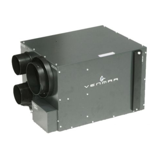
- Page 1 Installation and User Manual VB0063 AE60 - EA 1500 - HV 1.5 RESIDENTIAL USE ONLY READ AND SAVE THESE INSTRUCTIONS INSTALLER: LEAVE THIS MANUAL TO THE HOMEOWNER. HOMEOWNER: USE AND CARE INFORMATION ON PAGES 20 TO 24. ADDRESS OF YOUR INSTALLER 06095 .
- Page 2 6. Do not use the AE60, EA 1500 or HV 1.5 unit when varnishing. Furthermore, if the unit is installed in the attic, it is highly recommended to block the stale air intake and fresh air register. The varnish vapors may damage the unit.
-
Page 3: Table Of Contents
TABLE OF CONTENTS 1. Y ................4 NIT AND ITS URPOSE 2. T ................5-6 YPICAL NSTALLATIONS 2.1 B ..................5 ASEMENT NSTALLATION 2.2 A ....................5 TTIC NSTALLATION 2.3 M .................. 6 OUNTING ONSIDERATIONS 3. I ..................7-17 NSTALL THE 3.1 L ................ -
Page 4: Your
1. Y NIT AND ITS URPOSE OPERATIONAL PRINCIPLES The air exchanger is designed to eliminate problems of excessive humidity, to steady the temperature and the humidity and to filter and purify the air inside your house. The air exchanger carries out the following operations: AIR RECIRCULATION: The system recirculates the air inside the house, without exchanging with the outside. -
Page 5: Typical Installations
2. T YPICAL NSTALLATIONS Use the following illustrations as guidelines to help you decide where your unit will be installed. The unit should be hung to the joists, using chains and springs (included). If needed, this unit can be installed upside down. For more details, see Point 3. I NSTALL THE In every case, bathroom fan and a range hood should be used to exhaust stale air. -
Page 6: Mountingc
2. T ’ YPICAL NSTALLATIONS CONT 2.3 M OUNTING ONSIDERATIONS This unit can be used for a retrofit application. Connect the existing ducts to the corresponding unit ports. If the previous stale air to outside duct and fresh air from outside duct are 5’’ diameter, install the 5’’ diameter adapters (included) over each of the corresponding unit ports. -
Page 7: Nstall The
3. I NSTALL THE 3.1 L OCATING AND OUNTING THE Choose an appropriate location for the unit, far from the areas of the house where peace and quiet are desired. • So as to provide easy access for filter maintenance (sometimes, by installing the unit upside down, it becomes easier to get to the filter). -
Page 8: Lanning Of The
3. I ’ NSTALL THE CONT 3.4 P LANNING OF THE UCTWORK • Keep it simple. Plan for a minimum number of bends and joints. Keep the length of the insulated ducts to a minimum. • Do not use wall cavities as ducts. Do not use branch lines smaller than 4’’... - Page 9 3. I ’ NSTALL THE CONT 3.5 I 6” D ’ NSTALLING UCTS AND EGISTERS CONT 3.5.3 S UGGESTED EGISTER OCATIONS BUNGALOW Basement stairwell (A): Open, lateral. One stale air exhaust register (1) in the highest lived-in level of the house and one fresh air distribution register (2) in the lowest lived-in level of the house.
- Page 10 3. I ’ NSTALL THE CONT 3.5 I 6” D ’ NSTALLING UCTS AND EGISTERS CONT 3.5.3 S ’ UGGESTED EGISTER OCATIONS CONT MULTI-LEVEL Basement stairwell (A): Open, central. Two stale air exhaust registers (1) in the upper lived-in levels of the house and one fresh air distribution register (2) in the lowest lived-in level of the house.
-
Page 11: Ducts Installation
3. I ’ NSTALL THE CONT 3.6 I NSULATED LEXIBLE UCTS NSTALLATION CAUTION Make sure the vapor barrier on the insulated ducts does not tear during installation to avoid condensation within the ducts. Use the following procedure for connecting the insulated flexible ducts to the unit ports (exhaust to outdoors and fresh air from outdoors). - Page 12 3. I ’ NSTALL THE CONT 3.7 E ’ XTERIOR PENING NSTALLATION CONT 3.7.1 T ’ ANDEM RANSITION WITH XTERIOR CONT 1. For each duct, pull back the insulation to expose the interior flexible duct. CAUTION Always connect the exhaust air to outside duct on top section of the Tandem transition.
- Page 13 3. I ’ NSTALL THE CONT 3.7 E ’ XTERIOR PENING NSTALLATION CONT 3.7.1 T ’ ANDEM RANSITION WITH XTERIOR CONT The dual exterior hood must be installed at a minimum distance of 18 inches (457 mm) from the ground. See illustration at right.
- Page 14 3. I ’ NSTALL THE CONT 3.7 E ’ XTERIOR PENING NSTALLATION CONT 3.7.1 T ’ ANDEM RANSITION WITH XTERIOR CONT MAS TREE PIN 2. Join the end of the Tandem transition to the rear of the exterior backplate. Secure with 2 Xmas tree pins and seal properly with duct tape.
- Page 15 3. I ’ NSTALL THE CONT 3.7 E ’ XTERIOR PENING NSTALLATION CONT 3.7.2 L OCATING XTERIOR OODS If this unit installation needs to have 2 exterior hoods, an additional exterior hood must be bought (sold separately, single exterior hood, part number 13940). Choose an appropriate location for installing the exterior hoods.
- Page 16 3. I ’ NSTALL THE CONT 3.7 E ’ XTERIOR PENING NSTALLATION CONT 3.7.3 C ONNECTING NSULATED UCTS TO XTERIOR OODS CAUTION Make sure the insulated ductwork vapor barrier does not tear during installation. 1. For each exterior hood, using a jig saw, cut a 6’’ diameter hole in the exterior wall.
- Page 17 3. I ’ NSTALL THE CONT 3.7 E ’ XTERIOR PENING NSTALLATION CONT 3.7.4 L OCATING OFFIT RILLES If this unit is installed in the attic, use the installation kit no. EA20130 (not available in the U.S.A.). Choose an appropriate location for installing the soffit grilles (included in the installation kit no.
-
Page 18: Exterior Opening 4. Control
4. C ONTROL 4.1 I NSTALLATION OF THE ONTROL WARNING Always disconnect the unit before making any connections. Failure in disconnecting power could result in electrical shock or damage of the control or electronic module of the unit. CAUTION Never install more than one control per unit. 1. -
Page 19: Control Control
4. C ’ ONTROL CONT 4.1 I ’ NSTALLATION OF THE ONTROL CONT 5. Run the other end of the cable through the wall. Reinstall the cover plate. Using wall anchors (not included) and provided screws, mount the control on the wall. - Page 20 4. C ’ ONTROL CONT 4.1 I ’ NSTALLATION OF THE ONTROL CONT 9. Splice back the end of the cable to access the 4 wires. Remove the insulated sleeve of each wire ends. Connect each wires in their corresponding terminal (YELLOW in “Y”...
- Page 21 4. C ’ ONTROL CONT 4.2 O ’ PERATING THE ONTROL CONT • “O”: To stop the unit, slide the button on this position. • MINIMUM: For a day-to-day usage, slide the button on this position. The unit then will operate on normal speed. •...
-
Page 22: Operating The 5. Maintenance
5. M AINTENANCE WARNING Risk of electrical shocks. Before performing any maintenance or servicing, always disconnect the unit from its power source. It is recommended to wear safety glasses and gloves when performing maintenance or servicing. 5.1 B IANNUAL AINTENANCE 1. -
Page 23: Aintenance
5. M ’ AINTENANCE CONT 5.2 A NNUAL AINTENANCE 1. Disconnect the unit power cord. VD0005 2. Clean filter • Remove filter. • Vacuum to remove most of the dust. • Wash with a mixture of warm water and mild soap. -
Page 24: Biannual M 5.2 Annual M 5.3 Master Reset
5. M ’ AINTENANCE CONT 5.3 M ASTER ESET Use the master reset only if you perform the annual maintenance before the annual maintenance indicator is on. By inserting a small rod (e.g.: paper clip end) during 5 seconds and more into the control reset hole, a master reset will be done and both biannual and annual maintenance filter are reset. -
Page 25: Troubleshooting 7. Warranty
If in home service is not available, the product will be repaired or replaced at Venmar discretion by the nearest authorized service provider. The unit removal and reinstallation works are under the customer responsibility, and VENMAR VENTILATION inc. - Page 26 To contact Venmar Ventilation inc. warranty service call 1-800-567-3855. In order to qualify for a warranty claim, it is essential that the owner of a Venmar whole-house air exchanger must have the model and serial number along with a copy of the proof of the original purchase. In each case, travel costs are not covered by this warranty.
Need help?
Do you have a question about the EA 1500 and is the answer not in the manual?
Questions and answers