Table of Contents
Advertisement
Quick Links
Installation Manual
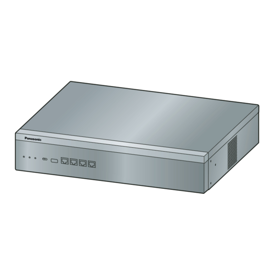
Video Intercom System — Control Box
VL-VN1800
Model No.
Thank you for purchasing this Panasonic product.
Please read this manual carefully before using this product and save this manual for future use.
In particular, be sure to read "1.1 For Your Safety, page 8" before using this product.
PNMPR Software File Version 001.00000 or later
Manuals and supporting information are provided on the Panasonic Web site at:
https://panasonic.net/cns/pcc/support/intercom/vn1900
Advertisement
Table of Contents
Troubleshooting

Related Manuals for Panasonic VL-VN1800


Summary of Contents for Panasonic VL-VN1800
- Page 1 Please read this manual carefully before using this product and save this manual for future use. In particular, be sure to read "1.1 For Your Safety, page 8" before using this product. PNMPR Software File Version 001.00000 or later Manuals and supporting information are provided on the Panasonic Web site at: https://panasonic.net/cns/pcc/support/intercom/vn1900...
- Page 2 System Components System Components Equipment Compatibility The Control Box can be used with Panasonic SIP phones. Consult your dealer for more information. Compatible Panasonic SIP phones • KX-HDV130 • KX-HDV230 • KX-HDV430 As of March 2017 The Control Box also supports the following equipment: •...
- Page 3 Introduction Introduction This Installation Manual is designed to serve as an overall technical reference for the Panasonic Video Intercom System Control Box. It provides instructions for installing the hardware, and programming the Control Box using Web Maintenance Console. The Structure of this Manual...
- Page 4 Introduction Installation Manual...
-
Page 5: Table Of Contents
Table of Contents Table of Contents 1 Safety Precautions ................. 7 For Your Safety ........................ 8 Important Safety Instructions ..................13 Precautions ........................14 Data Security ......................... 17 2 System Outline ..................19 Basic System Construction ..................20 2.1.1 System Configurations ....................20 2.1.2 System configuration .................... - Page 6 Table of Contents 6.1.3 VLAN (Virtual LAN) ....................... 55 6.1.4 Jitter Buffer ........................55 6.1.5 Voice Activity Detection (VAD) ..................55 6.1.6 Network Configuration ....................55 6.1.7 Network Devices ......................56 6.1.8 Network Time Protocol (NTP) ..................56 Port Security ........................57 7 Troubleshooting ...................
-
Page 7: Safety Precautions
Section 1 Safety Precautions This section provides important information intended to prevent personal injury and property damage. Installation Manual... -
Page 8: For Your Safety
This symbol is used to alert users to a specific operating procedure that must be followed in order to operate the unit safely. Notice Panasonic assumes no responsibility for injuries or property damage resulting from failures arising out of improper installation or operation inconsistent with this documentation. WARNING For All Telephone Equipment •... - Page 9 • Do not attempt to repair the power cord or plug. If the power cord or plug is damaged or frayed, contact an authorised Panasonic Factory Service Centre for a replacement. • Do not mount the unit on a wall; it is designed to be mounted only on a 19-inch rack. If it is mounted on a wall, it may fall and cause serious injury.
- Page 10 1.1 For Your Safety • Do not open the top cover of the unit. Panasonic assumes no responsibility for injuries or property damage resulting from doing so. • When mounting the unit on a 19-inch rack, only use the 19-inch rack mounting equipment (attachment bracket, screws) included with the unit.
- Page 11 1.1 For Your Safety For the Control Box • Do not install the system in the following locations: In direct sunlight and hot, cold, or humid places. (Temperature range: 0 ℃ to 40 ℃) Areas where sulphuric gases may be present, such as near thermal springs. Near devices that generate high frequencies, such as sewing machines or electric welders.
- Page 12 1.1 For Your Safety • Unplug the system from its power source when wiring, and plug the system back in only after all wiring is completed. • For earthing wire, green-and-yellow insulation is required, and the cross-sectional area of the conductor must be more than 0.75 mm or 18 AWG.
-
Page 13: Important Safety Instructions
1.2 Important Safety Instructions 1.2 Important Safety Instructions When using your telephone equipment, basic safety precautions should always be followed to reduce the risk of fire, electric shock and injury to persons, including the following: • Do not use the unit near water, for example, near a bathtub, wash bowl, kitchen sink, or laundry tub, in a wet basement, or near a swimming pool. -
Page 14: Precautions
1.3 Precautions 1.3 Precautions General information • Before attempting to connect or operate this product, please read the nameplate on the bottom or rear of the product. • In the event of problems, you should contact your equipment supplier in the first instance. •... - Page 15 A replacement fuse cover can be purchased from your local Panasonic dealer. IF THE FITTED MOULDED PLUG IS UNSUITABLE FOR THE AC OUTLET IN YOUR PREMISES, THEN THE FUSE SHOULD BE REMOVED AND THE PLUG CUT OFF AND DISPOSED OF SAFELY.
- Page 16 1.3 Precautions • This equipment is not capable, under all operating conditions, of correct operation at the higher speeds for which it is designed. Telecom will accept no responsibility should difficulties arise in such circumstances. • Some parameters required for compliance with Telecom’s Telepermit requirements are dependent on the equipment (Server) associated with this modem.
-
Page 17: Data Security
Note that user information may be deleted or initialised when the product is repaired. Refer all repairs to a trusted Panasonic service centre. Protect user information stored on the computer used to configure the system. - Page 18 1.4 Data Security You will never receive enquires about passwords from Panasonic. Installation Manual...
-
Page 19: System Outline
Section 2 System Outline This section provides general information on the Control Box, including the system capacity and specifications. Installation Manual... -
Page 20: Basic System Construction
Support up to 2000 SIP devices on a system with a Control Box (example 1) R1 R2 R3 R1 R2 R3 Mobile network Smartphone Router <Gate> Public IP address Push VL-VN1800 Internet Internet server <Reception / Guard> Control box Installation Manual... - Page 21 Smartphone Router <Gate> Public IP address Push VL-VN1800 Internet Internet server <Reception / Guard> Control box "SIP devices" include lobby stations, room monitors, door stations, SIP phones, and smartphones. A router connected to the internet with a public IP address is required. (A DDNS server may be required depending on the contract of the Internet Service Provider.) Router configuration is required in order for the [Video Intercom System] app to...
- Page 22 By installing the [Video Intercom System] app on a smartphone, you can expand the features available when using the VL-VN1800 control box system with a smartphone. In order to use the [Video Intercom System] app, you must download it to your smartphone and register your smartphones with your "main"...
- Page 23 2.1.2 System configuration "Main" room monitor "Sub" room monitor Smartphone Depending on your facility's system configuration, in order to establish a system only with smartphones for residences that do not have a room monitor, an activation key (VL-AKA005; sold separately) is required. Depending on your facility's system configuration, the number of smartphones that can be registered differs.
-
Page 24: Specifications
2.2 Specifications 2.2 Specifications 2.2.1 General Description Main CPU Intel ATOM E3845 (Quad core 1.91 GHz) Power Input Rated Voltage AC 100 – 240 V Frequency 50/60 Hz Current/Power 0.95 - 0.6 A Power Consumption Under 50 W External Backup Battery External battery port is not supported. -
Page 25: Information About The Activation Keys
Section 3 Information about the Activation Keys Installation Manual... -
Page 26: Information About The Activation Keys
The activation key is specified in the leaflet supplied with VL-AKA005 *1, *2 Activation keys are sold separately. Activation keys are used for linking VL-VN1800 control boxes (MPR-ID) to smartphones and allow smartphones to use the Video Intercom System without using room monitors. -
Page 27: Installation
Section 4 Installation This section describes the procedures to install the Control Box. Detailed instructions for planning the installation site, installing the main unit, and cabling of peripheral equipment are provided. Installation Manual... -
Page 28: Before Installation
Be sure to comply with all applicable laws, regulations, and guidelines. Notice Panasonic assumes no responsibility for injuries or property damage resulting from failures arising out of improper installation or operation inconsistent with this documentation. Installation Precautions The Control Box is suitable for mounting on a 19-inch rack and should be installed in a location where it is accessible for inspections and maintenance. -
Page 29: Installation Of The Control Box
4.2 Installation of the Control Box • Unplug the system from its power source when wiring, and plug the system back in only after all wiring is completed. Notice • Mis-wiring may cause the Control Box to operate improperly. • If an extension does not operate properly, disconnect the telephone from the extension line and connect it again, or turn off the Control Box using the power switch, then turn it on again. -
Page 30: Names And Locations
4.2.2 Names and Locations 4.2.2 Names and Locations Front Back B C D E F G H A. STATUS Indicator B. SYSTEM MODE Indicator C. System Mode Switch D. USB Port E. MNT Port F. LAN 1 Port G. LAN 2 Port H. - Page 31 4.2.2 Names and Locations MNT Port/LAN Port/WAN Port (1000BASE-T) Input (I)/ Signal Name Function Output (O) TRD0 (+) Transmit and receive data 0 (+) TRD0 (-) Transmit and receive data 0 (-) TRD1 (+) Transmit and receive data 1 (+) TRD2 (+) Transmit and receive data 2 (+) TRD2 (-)
-
Page 32: Frame Earth Connection
4.2.3 Frame Earth Connection 4.2.3 Frame Earth Connection Loosen the screw. Insert an earthing wire (user- supplied). Tighten the screw. Connect the earthing wire to earth. A. Screw B. Earthing wire (1) To earth WARNING • Proper earthing (connection to earth) is very important to reduce the risk to the user of electrocution or to protect the unit from the bad effects of external noise in the case of a lightning strike. - Page 33 4.2.4 19-inch Rack Mounting • If the unit is not installed properly using the securing correct methods, the unit may fall causing serious damage. • When this product is no longer in use, make sure to detach it from the rack. Notice When mounting the unit on a 19-inch rack, confirm that the rated current listed on the unit’s name plate does not exceed the threshold current for the breaker.
-
Page 34: Connection Of Peripherals
4.3 Connection of Peripherals 4.3 Connection of Peripherals Maximum Distance 100 m MNT Port PC (via MNT Port) A PC can be connected to the Control Box via the MNT port of the Control Box. It is used for system programming, diagnostics and external system database storage (save/load) functions. -
Page 35: Lan Connection
4.4 LAN Connection Pin Assignments for 1000BASE-T Input (I)/ Signal Name Function Output (O) TRD0 (+) Transmit and receive data 0 (+) TRD0 (-) Transmit and receive data 0 (-) TRD1 (+) Transmit and receive data 1 (+) TRD2 (+) Transmit and receive data 2 (+) TRD2 (-) Transmit and receive data 2 (-) - Page 36 4.4.1 LAN Connection for the Main Unit LAN Port Switching Hub Ethernet Cable Connection for 10BASE-T/100BASE-TX Switching Hub Control Box (LAN Port) Pin No. Pin No. Signal Name Signal Name Connection for 1000BASE-T Switching Hub Control Box (LAN Port) Pin No. Pin No.
-
Page 37: Lan Connections For Ip Telephones
4.4.2 LAN Connections for IP Telephones • Make sure to create a spanning tree for LAN connection in order to prevent loops from occurring in a multi-bridged environment. Otherwise, some packets may circulate for long periods of time and eventually system performance may degrade. •... - Page 38 4.5 Starting the Control Box Installing the Hook Clip for the AC Power Cord Insert the hook clip into the hook clip hole. Note Use only the hook clip included with the Control Box. Connecting the AC Power Cord Plug the AC power cord into the Control Box and pass the cord through the hook clip as indicated. Push the hook clip in the direction of the arrow until it clicks.
- Page 39 4.5 Starting the Control Box Note After the Control Box is initialised, you must configure the mandatory settings with Quick Setup Wizard. For details refer to "5.4.1 Quick Setup Wizard". Slide the System Mode Switch to the "SYSTEM INITIALIZE" position. A.
- Page 40 4.5 Starting the Control Box Installation Manual...
-
Page 41: Programming Information
Section 5 Programming Information This section describes the structure and functions of the Web Maintenance Console for programming IP telephones and the Control Box. Further information on programming the Control Box for use with a VoIP network is included. Installation Manual... -
Page 42: Overview Of Web Maintenance Console
5.1 Overview of Web Maintenance Console 5.1 Overview of Web Maintenance Console Web Maintenance Console is designed to serve as an overall system programming reference for the Control Box. You can programme and control the Control Box over an IP network using Web Maintenance Console. This section describes programming basic items using Web Maintenance Console. - Page 43 5.2 PC Connection Direct Connection MNT Port To LAN Port Notice When connecting the PC to the MNT port, if the PC is set to obtain the IP address automatically, the IP address of the PC will be set to an appropriate IP address to establish a connection to the Control Box. Note •...
-
Page 44: Starting Web Maintenance Console
5.3 Starting Web Maintenance Console Connection via Virtual Private Network (VPN) Router LAN Port Router Switching Hub Notice To access the Control Box via VPN, the PC must be in the same VPN. Note For details about connecting a switching hub to the Control Box, refer to "4.4.1 LAN Connection for the Main Unit". - Page 45 5.3 Starting Web Maintenance Console Please provide all system passwords to the customer. To avoid unauthorised access and possible abuse of the Control Box, keep the passwords secret, and inform the customer of the importance of the passwords, and the possible dangers if they become known to others.
-
Page 46: Programming The Control Box
The user name is "INSTALLER". – The default password is "1234". Welcome to Panasonic VL-VN1800 On this screen, you can either import a previously configured system data file or proceed to manually configure the Control Box’s settings. To import a previously configured system data file Log in to Web Maintenance Console (interactive mode). - Page 47 5.4.1 Quick Setup Wizard • Port: Enter the TCP Port for the SNTP Server. Daylight Saving • Select whether to enable or disable summer time (daylight saving time). User On this screen, you can specify the settings for users and extensions for the Control Box. When you have finished specifying the settings, click Next to continue.
-
Page 48: After Quick Setup Wizard Has Been Completed
5.4.2 After Quick Setup Wizard has been Completed IP Address for main unit Select the method for setting the IP address information. • Obtain an IP address automatically • Use the following IP address If you selected Use the following IP address, specify the following settings. •... -
Page 49: Installing Additional Activation Keys
Installing the Activation Key Files First, make sure that the VL-VN1800 control box is connected to an outside network and a PC. Log in to Web Maintenance Console using the Installer level account. -
Page 50: Registering Ip Telephones
5.6 Registering IP Telephones The IP address of the SIP phone, the subnet mask address, and the default gateway address can be assigned to the SIP phone automatically by the DHCP server. The Control Box’s IP address must be assigned manually on the SIP phone side. For instructions, refer to the documentation of the SIP phone. -
Page 51: Registering Ip Telephones
5.6.2 De-registering IP Telephones Click Select All. Click Execute to copy each Extension Number to Password. • When copying extension numbers to passwords, you can also use the icon on the bottom left of the Virtual SIP Extension Port Property screen. Programme the SIP extension you wish to register. -
Page 52: Router Setting
5.8 Router Setting 5.8 Router Setting In order to operate this system, applicable settings for the router must be configured. Control box Internet (+ Built-in Media Relay Gateway) Switching hub Router Smartphone application Mobile Internet Lobby station Room monitor Door station SIP phone Network camera Main Site... -
Page 53: Networking Information
Section 6 Networking Information This section provides information about topics such as using the Control Box in a VoIP network, and the TCP ports used by the Control Box. Further information on programming the Control Box for use with a VoIP network is included. -
Page 54: Information About Using An Ip Network
6.1 Information about Using an IP Network 6.1 Information about Using an IP Network This section explains common IP network information necessary for setting up networks. 6.1.1 Using a VoIP Network with the Control Box This Control Box supports SIP (Session Initiation Protocol) devices (Lobby Station, Door Station, and Room Monitor) and SIP phones for communication on a Voice over Internet Protocol (VoIP) network. -
Page 55: Vlan (Virtual Lan)
6.1.3 VLAN (Virtual LAN) Note • The DHCP Server feature is disabled by default. To enable the feature, refer to "5.4.3 Enabling the DHCP Server Feature". • An IP telephone and the mother board/DSP card cannot request IP addresses from a DHCP server on another LAN (connected through an IP network). -
Page 56: Network Devices
6.1.7 Network Devices Note When the DHCP Server feature is disabled and external DHCP servers are not used, static IP addressing must also be enabled for all IP telephones. 6.1.7 Network Devices You must evaluate the network devices that are used in the existing network to see if a VoIP network can be implemented. -
Page 57: Port Security
6.2 Port Security 6.2 Port Security The following table shows the Control Box’s ports used for IP communications. Any access to the ports not in this list is ignored. Port Numbers for LAN Port Port Changeable/ Protocol Application Client/Server Number Fixed TCP/UDP SMTP... - Page 58 6.2 Port Security Port Changeable/ Protocol Application Client/Server Number Fixed 21000– RTP/RTCP for NAT traversal Changeable 21511 Follow the import file setting values of Quick Setup. Installation Manual...
-
Page 59: Troubleshooting
Section 7 Troubleshooting This section provides information on the Control Box and telephone troubleshooting. Installation Manual... -
Page 60: Troubleshooting
7.1 Troubleshooting 7.1 Troubleshooting 7.1.1 Installation PROBLEM PROBABLE CAUSE SOLUTION Smartphones cannot be • • Not enough activation Purchase additional activation key codes. registered. keys Please consult a certified dealer for details. You cannot make/receive • • Poor connection Make sure that an 8-pin twisted pair cable calls via an IP network. -
Page 61: Operation
7.1.2 Operation 7.1.2 Operation PROBLEM PROBABLE CAUSE SOLUTION • • • Whenever you try to The status of the port Change the port status from Out of make calls using a SIP that the SIP phone is Service to In Service using Web phone, a busy tone is connected to is Out of Maintenance Console. -
Page 62: Troubleshooting By Error Log
7.1.4 Troubleshooting by Error Log A. System Mode Switch Start the Web Maintenance Console. Log in using an Administrator level account. On the Home screen, click Maintenance → System Control → System Reset → System Reset. Follow the prompts. Restarting the Control Box will start. To reset the system at a preset time: Confirm that the System Mode Switch is in the "NORMAL"... - Page 63 7.1.4 Troubleshooting by Error Log Example: Web Maintenance Console Example: Station Message Detail Recording (SMDR) 01/01/10 01:00AM MJ ALM #014 00 10000 FAN Alarm 01/01/10 01:29AM MN ALM #533 01 50401 Unit start up error Description Item Description Date The date of the error detection. Time The time of the error detection.
- Page 64 7.1.4 Troubleshooting by Error Log [Sample] List of Errors and Solutions For each error code, the error message, probable cause, and solutions are explained. Installation Manual...
-
Page 65: Appendix
Section 8 Appendix This section provides information about System Prompt Languages. Installation Manual... -
Page 66: System Prompt Languages
8.1 System Prompt Languages 8.1 System Prompt Languages System prompt languages stored in the Storage Memory Card (installed by default) No. 1 (Primary) UK-English No. 2 Spanish No. 3 French No. 4 German No. 5 Dutch No. 6 Italian No. 7 Swedish Installation Manual... - Page 67 Note Installation Manual...
- Page 68 DEALER'S TEL. NO. For Europe For information of Compliance with EU relevant Regulatory Directives, Contact to Authorised Representative: Panasonic Testing Centre Panasonic Marketing Europe GmbH Winsbergring 15, 22525 Hamburg, Germany 1006, Oaza Kadoma, Kadoma-shi, Osaka 571-8501, Japan http://www.panasonic.com © Panasonic Corporation 2019...