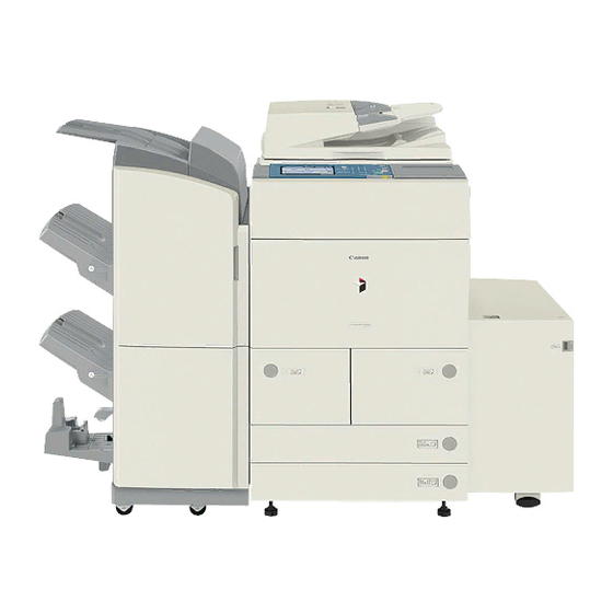
Canon IR6570 Series Service Manual
Hide thumbs
Also See for IR6570 Series:
- Service manual (684 pages) ,
- Manual (508 pages) ,
- Portable manual (320 pages)
Advertisement
Quick Links
Advertisement

Summary of Contents for Canon IR6570 Series
- Page 1 Service Manual iR6570/5570 Series Feb 21 2005...
- Page 3 When changes occur in applicable products or in the contents of this manual, Canon will release technical information as the need arises. In the event of major changes in the contents of this manual over a long or short period, Canon will issue a new edition of this manual.
-
Page 4: Symbols Used
Introduction Symbols Used This documentation uses the following symbols to indicate special information: Symbol Description Indicates an item of a non-specific nature, possibly classified as Note, Caution, or Warning. Indicates an item requiring care to avoid electric shocks. Indicates an item requiring care to avoid combustion (fire). Indicates an item prohibiting disassembly to avoid electric shocks or problems. - Page 5 Introduction The following rules apply throughout this Service Manual: 1. Each chapter contains sections explaining the purpose of specific functions and the relationship between electrical and mechanical systems with reference to the timing of operation. In the diagrams, represents the path of mechanical drive; where a signal name accompanies the symbol , the arrow indicates the direction of the electric signal.
- Page 7 Contents Contents Chapter 1 Introduction 1.1 System Construction............................1- 1 1.1.1System Configuration with Input/Output Accessories ................1- 1 1.1.2System Configuration with Printing/Transmission Accessories (230V) ............ 1- 2 1.1.3Functions and Printing/Transmission Accessories (230V) ................. 1- 3 1.2 Product Specifications............................1- 4 1.2.1 Names of Parts ............................1- 4 1.2.1.1 External view............................
- Page 8 Contents 2.1.2Checking the Contents ..........................2- 3 2.1.3Name of Parts .............................. 2- 6 2.2 Unpacking and Installation ..........................2- 8 2.2.1Points to Note Before Starting the Work ..................... 2- 8 2.2.2Unpacking..............................2- 8 2.2.3Installing the Scanner ..........................2- 10 2.2.4Installing the Fixing Assembly ........................2- 10 2.2.5Checking the Corona Assembly and the Dust-proofing Glass ..............2- 11 2.2.6Installing the Developing Assembly......................
- Page 9 Contents Chapter 3 Basic Operation 3.1 Construction ..............................3- 1 3.1.1Functional Construction ..........................3- 1 3.1.2Wiring Diagram of the Major PCBs......................3- 1 3.1.3Controlling the Main Motor (M2) ....................... 3- 2 3.2 Basic Sequence..............................3- 4 3.2.1Basic Sequence of Operation (at power-on; 30-sec start-up mode) ............3- 4 3.2.2Basic Sequence of Operation (at power-on;...
- Page 10 Contents 4.7.5 HDD ................................4- 24 4.7.5.1 Removing the HDD ........................... 4- 24 4.7.5.2 After Replacing the HDD ........................4- 24 4.7.6 Controller Fan ............................4- 24 4.7.6.1 Removing the Controller Cooling Fan....................4- 24 Chapter 5 Original Exposure System 5.1 Construction............................... 5- 1 5.1.1Specifications, Controls, and Functions ......................
- Page 11 Contents 5.4.2 Copyboard glass............................5- 27 5.4.2.1 Removing Copyboard Glass......................5- 27 5.4.2.2 When Replacing the Platen Board Glass................... 5- 28 5.4.3 Scanning Lamp ............................5- 28 5.4.3.1 Removing the Copyboard Glass......................5- 28 5.4.3.2 Removing the Right Cover (upper) ....................5- 29 5.4.3.3 Removing the Reader Right Cover....................
- Page 12 Contents 5.4.12.3 Removing the Right Cover (upper) ....................5- 47 5.4.12.4 Removing the Reader Right Cover....................5- 48 5.4.12.5 Removing the Left Cover (upper)....................5- 48 5.4.12.6 Removing the Reader Left Cover ....................5- 48 5.4.12.7 Removing the Reader Front Cover ....................5- 48 5.4.12.8 Removing the Reader Unit Rear Cover ...................
- Page 13 Contents 7.4.6APC Correction ............................7- 12 7.4.7Adjusting the Density in Various Modes ....................7- 13 7.5 Charging Mechanism ............................7- 15 7.5.1 Controlling Pre-Exposure LED......................... 7- 15 7.5.1.1 Pre-Exposure LED Control ....................... 7- 15 7.5.2 Primary Charging Mechanism ........................7- 15 7.5.2.1 Overview ............................
- Page 14 Contents 7.10.3.1 Removing the Primary Fan Duct ..................... 7- 42 7.10.3.2 Removing the Primary Charging Assembly ..................7- 42 7.10.4 Pre-Transfer Charging Assembly......................7- 43 7.10.4.1 Removing the Primary Fan Duct ..................... 7- 43 7.10.4.2 Removing the Pre-Transfer Charging Assembly................7- 43 7.10.5 Photosensitive Drum ..........................
- Page 15 Contents 7.10.10.4 Removing the Hopper Supply Motor .................... 7- 65 7.10.11 Hopper Strring Motor ........................... 7- 66 7.10.11.1 Removing the Primary Fan Duct....................7- 66 7.10.11.2 Removing the Right Cover (upper) ....................7- 67 7.10.11.3 Removing the Hopper Stirring Motor ................... 7- 67 7.10.12 Developing Assembly ...........................
- Page 16 Contents 8.3 Detecting Jams..............................8- 10 8.3.1 Jam Detection Outline ..........................8- 10 8.3.1.1 Outline ............................... 8- 10 8.3.1.2 Jam History ............................8- 11 8.3.2 Delay Jams ..............................8- 12 8.3.2.1 Cassette Pickup Assembly (right deck, left deck, cassette 3/4)............8- 12 8.3.2.2 Other Delay Jam ..........................
- Page 17 Contents 8.10.2.1 Removing the Right Deck/ Cassette Pickup Assembly..............8- 46 8.10.3 Cassette Pickup Motor ..........................8- 46 8.10.3.1 Removing the Rear Cover (upper) ....................8- 46 8.10.3.2 Removing the Rear Cover (lower) ....................8- 47 8.10.3.3 Removing the Main Controller Box ....................8- 47 8.10.3.4 Removing the Right Cover (lower rear)..................
- Page 18 Contents 8.10.13.1 Removing the Manual Feed Pull-Out Roller Unit ................. 8- 63 8.10.13.2 Removing the Manual Feed Pull-Out Roller ................. 8- 64 8.10.14 Manual Feed Roller ..........................8- 64 8.10.14.1 Removing the Manual Feed Pull-Out Roller Unit ................. 8- 64 8.10.14.2 Removing the Manual Feeding Roller...................
- Page 19 Contents 8.10.24.3 Removing the Main Controller Box ....................8- 85 8.10.24.4 Removing the Right Cover (lower rear)..................8- 86 8.10.24.5 Removing the Waste Toner Bottle Holder ..................8- 86 8.10.24.6 Removing the Vertical Path Lower Motor ..................8- 87 8.10.25 Fixing Feeding Unit Releasing Lever Sensor ..................8- 87 8.10.25.1 Removing the Fixing Feed Unit ....................
- Page 20 Contents 9.2.8Sleep Mode ............................... 9- 11 9.2.9Copying/Printing Mode ..........................9- 12 9.2.10Down Sequence ............................9- 13 9.2.11Enhanced Fixing Mode..........................9- 13 9.2.12Heavy Paper Mode ..........................9- 14 9.2.13Transparency Mode ..........................9- 15 9.2.14Bond Paper Mode ............................ 9- 16 9.3 Various Control Mechanisms .......................... 9- 17 9.3.1 Fixing Drive System..........................


