Advertisement
Quick Links
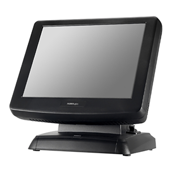
KS-7415/7415IR/7417/7417IR
Fanless Touch Terminal
User Manual
Package Contents
15" KS-7415/7415IR or 17" KS-7417/7417IR fanless touch terminal with
Gen 5/Gen 6/Gen 8.5 base stand (x 1)
Power adapter (x 1)
Power cord (x 1)
User manual (x 1)
Product Features
15" or 17" Resistive or IR touch screen
Spill-resistant design to prevent careless spill and provide easy cleaning for a
wide range of applications
Equipped with Intel Bay Trail-D Quad Core J1900 2.0GHz CPU and DDR3L
memory
Fanless design boasting quiet and anti-dust features
Patent aluminum die casting design for efficient cooling
Optional UPS (Embedded on board developed by Posiflex)support to avoid
sudden power loss
Patent finger lever "Gear Lock" to adjust the terminal tilt angle from 15° to 70°
Push-open cover to protect power switch from accidental shutdown
Bottom cable guide design and cover for safety and neat outlook
User-friendly mechanism for system upgrade and easy maintenance
16390900010 Ver.Original
http://www.posiflex.com
1
Advertisement

Related Manuals for POSIFLEX KS-7415


Summary of Contents for POSIFLEX KS-7415
- Page 1 KS-7415/7415IR/7417/7417IR Fanless Touch Terminal User Manual Package Contents 15” KS-7415/7415IR or 17” KS-7417/7417IR fanless touch terminal with Gen 5/Gen 6/Gen 8.5 base stand (x 1) Power adapter (x 1) Power cord (x 1) User manual (x 1) Product Features ...
- Page 2 Views of KS-7415/7415IR/7417/7417IR with Gen 5 Base Stand Front View Resistive or IR Touch Panel LED indicator Gen 5 Base Stand Rear View HDD Cover Release Button Cable Cover Cable Exit Side View Tilt Adjustment Lever Power Button Brightness Adjustment Button +...
- Page 3 Bottom View Rubber Feet with Fixing Screw Cable Holder Cable Groove Cable Passage Rubber Feet with Fixing Screw Views of KS-7415/7415IR/7417/7417IR with Gen 6 Base Stand Front View Resistive or IR Touch Panel LED indicator Gen 6 Base Stand Rear View...
- Page 4 USB Ports Bottom View Rubber Feet with Fixing Screw UPS Battery Bracket UPS Battery Compartment Rubber Feet with Fixing Screw Views of KS-7415/7415IR/7417/7417IR with Gen 8.5 Base Stand Front View Resistive or IR Touch Panel LED indicator Gen 8.5 Base Stand...
- Page 5 Rear View HDD Cover Release Button Base Stand Cover Cable Cover Cable Exit Side View Power Button Brightness Adjustment Button + Brightness Adjustment Button - USB Ports Bottom View Rubber Feet with Fixing Screw PoweredUSB Compartment Power adapter Compartment UPS Battery Compartment Rubber Feet with Fixing Screw...
- Page 6 Mounting your Terminal onto Gen 5/6/8.5 Base Stand Please refer to the instructions below to install the terminal onto the Gen 5/6/8.5 base stand. KS-7415 and Gen 8.5 base will be used in the following demonstration. Lay the terminal on a flat surface with its bottom I/O plate facing you.
- Page 7 Make sure the terminal is well mounted onto the base stand. Positioning your POS for a Perfect Viewing Angle The adjustable base stands designed for the terminal come in three different model, Gen 5/6/8.5, and allow you to determine an ideal position for your terminal using its unique tilt adjustment mechanism.
- Page 8 In most cases, KS-7415/7415IR/7417/7417IR will be set up beforehand in flat folded mode for shipping. After it is unpacked, you may re-adjust the terminal in either low profile mode or full extended mode according to your situation.
- Page 9 Position your terminal in Full Extended mode. Support the screen with one hand holding onto its bottom edge. Then, while pulling the lever backwards, move the display upwards until the lever is snapped into the lower hook to raise the screen as shown in the below figure. Lower hook Upper...
- Page 10 Return the terminal back to Flat Folded mode. After ensuring the cable cover is removed, support the screen with one hand holding onto its bottom edge. While pulling the lever backwards, release the lever back to the point above the upper hook as shown in the figure Push the cable cover back.
- Page 11 Pass the cord through the cable passage. Cable passage Place Gen 5 base stand in upright position and Cable passage make sure the cable can be pulled out of the cable passage. After mounting the terminal onto the base stand, connect the cable to the bottom I/O plate of your terminal.
- Page 12 Tilt the screen upwards, and then have the cables Cable exit pass through the cable exit. Connect the necessary cables to the I/O ports of the terminal. After making sure the cable is threaded out of the cable exit, put the base stand cover back into place. Cable Exit For Gen 8.5 Base Stand...
- Page 13 Installing Optional Upgrade Kits and Peripherals KS-7415/7415IR/7417/7417IR is an expandable model which allows you to upgrade its own capacity by additionally installing multiple peripheral devices, such as magnetic stripe reader (MSR), LCD monitor and cash drawer, according to your preference. The following will give you installation instructions on how to expand on your current POS system with these optional upgrade kits.
- Page 14 For 60W/80W Power adapter Lay your POS terminal with its screen facing downwards. Take the AC power adapter with its rubber feet facing you, and then insert it into the power adapter bracket. Attach the bracket to the wedged portions on the right-hand side of the power adapter compartment.
- Page 15 Neatly thread the cord along the bottom edge of the middle compartment (1), and then use the cable tie to hold the extra cable (2) as shown in the Cable tie figure. Secure the middle compartment bracket using two fixing screws. Lay the POS terminal on a flat surface with its rear facing towards you.
- Page 16 Lift the power adapter up against the top side of the compartment. Place two brackets separately on the top and bottom sides of the power adapter compartment as shown in the figure. Then, fasten two brackets with four fixing screws. Loosen two fixing screws to remove the bracket for the middle compartment.
- Page 17 To hold the power cord into place, attach the screw hole of power adapter holder to the hole at the bottom of Gen 8.5 base stand, and then use a fixing screw to secure the bracket. Installing UPS Battery to Gen 5/6/8.5 Base Stand UPS battery compartment can be found at the bottom of Gen 5/6/8.5 base stands, but the precise locations for installing UPS battery for each base stand are slightly different.
- Page 18 Place Gen 5 base stand in upright position and make sure the cable can be pulled out of the cable passage. After mounting the terminal onto the base stand, then connect the cable to the bottom I/O plate of your terminal. For Gen 6/8.5 Base Stand As shown in the figures below, well install UPS battery into the bottom of the base according to the base type you are using.
- Page 19 Operation Environment To prevent KS-7415/7415IR/7417/7417IR from overheating, it is strongly suggested to position your terminal in a well-ventilated working environment. In doing so, please be advised to keep the POS terminal at least 25mm away from other devices to ensure the...
-
Page 20: Specifications
USB 2.0 x 6 LAN Port 10 / 100 / 1000 Mb x 1 VGA Port VGA x 1, 12V support for Posiflex monitors CR Port 1, controlling 2 CR via optional Y-cable UPS Port Yes, for optional UPS battery...
Need help?
Do you have a question about the KS-7415 and is the answer not in the manual?
Questions and answers