Table of Contents
Advertisement
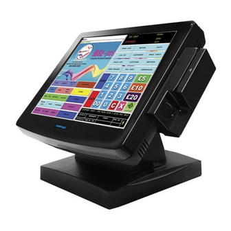
KS – 6715
Fan Free Touch Terminal
User's Manual
Rev.: A1
FCC Notes:
This equipment generates, uses, and can radiate radio frequency energy and, if not
installed and used in accordance with the instructions manual, may cause interference
to radio communications. It has been tested and found to comply with limits for a Class
A digital device pursuant to subpart J of Part 15 of FCC Rules, which are designed to
provide reasonable protection against interference when operated in a commercial
environment. Operation of this equipment in a residential area is likely to cause
interference in which case the user at his own expense will be required to take whatever
measures to correct the interference.
Warranty Limits:
Warranty terminates automatically when any person other than the authorized
technicians opens the machine. The user should consult his/her dealer for the problem
happened. Warranty voids if the user does not follow the instructions in application of
this merchandise. The manufacturer is by no means responsible for any damage or
hazard caused by improper application.
About This Manual:
Posiflex has made every effort for the accuracy of the content in this manual. However,
Posiflex Technology, Inc. will assume no liability for any technical inaccuracies or
editorial or other errors or omissions contained herein, nor for direct, indirect,
incidental, consequential or otherwise damages, including without limitation loss of
data or profits, resulting from the furnishing, performance, or use of this material.
This information is provided "as is" and Posiflex Technology, Inc. expressly disclaims
any warranties, expressed, implied or statutory, including without limitation implied
warranties of merchantability or fitness for particular purpose, good title and against
infringement.
The information in this manual contains only essential hardware concerns for general
user and is subject to change without notice. Posiflex Technology, Inc. reserves the
right to alter product designs, layouts or drivers without notification. The system
integrator shall provide applicative notices and arrangement for special options utilizing
this product. The user may find the most up to date information of the hardware from:
http://www.posiflex.com or http://www.posiflex.com.tw or http://www.posiflexusa.com
All data should be backed-up prior to the installation of any drive unit or storage
peripheral. Posiflex will not be responsible for any loss of data resulting from the use,
disuse or misuse of this or any other Posiflex product.
All rights are strictly reserved. No part of this documentation may be reproduced,
stored in a retrieval system, or transmitted in any form or by any means, electronic,
mechanical, photocopying, or otherwise, without prior express written consent from
Posiflex Technology, Inc. the publisher of this documentation.
© Copyright Posiflex Technology, Inc. 2012
All brand and product names and trademarks are the property of their respective holders.
Part 1
P/N: 16510900020
Advertisement
Table of Contents

Related Manuals for POSIFLEX KS – 6715


Summary of Contents for POSIFLEX KS – 6715
- Page 1 About This Manual: Posiflex has made every effort for the accuracy of the content in this manual. However, Posiflex Technology, Inc. will assume no liability for any technical inaccuracies or editorial or other errors or omissions contained herein, nor for direct, indirect, incidental, consequential or otherwise damages, including without limitation loss of data or profits, resulting from the furnishing, performance, or use of this material.
- Page 2 ALERT TO OUR HONORABLE CUSTOMERS: Please always read thoroughly all the instructions and documents delivered with the product before you do anything about it. Don’t take any premature action before you have a full understanding of the consequences. This product contains inside a Lithium battery. Please always follow local environmental protection laws / regulations for disposal of used batteries and always replace only with battery of same type.
-
Page 3: Install Guide
INSTALL GUIDE After pass through all of connecting cable from the base as instruct in part 10 & 11, please follow the steps to install the terminal and base stand carefully when first time open the carton. Since the monitor and stand are packaged separately, please Take Out and Hold the PE foams Carefully and DO NOT detach and drop it. -
Page 4: Parts Identification
INTRODUCTION PRODUCT PICTURES for Gen.5 Base Stand Front Views Rear Views Side Views Inside touch open door Base Stand and Bottom View PARTS IDENTIFICATION Main Unit Touch panel / LCD panel Power indicator Gen 5 base stand Screw holes for optional rear top mount kit such as PD-310 or Part 4... -
Page 5: Product Pictures
PD-2604 or LM-2312 or LM-8035 HDD cover Power switch Brightness adjust push button “+” Brightness adjust push button “-” 10. USB ports 11. Base stand 12. Compression lock for base stand cover 13. Cable exit 14. Cable groove 15. Cable exit 16. -
Page 6: Product Features
Base Stand and Bottom View PARTS IDENTIFICATION Touch panel / optional flat screen LCD Power indicator Gen 6 slim base Screw holes for optional rear top mount kit PD-310 or PD-2604 or LM-2312 or LM-8035 HDD cover Power switch Brightness adjust push button “+” Brightness adjust push button “-”... - Page 7 High quality 15” TFT active matrix LCD panel LCD panel with easy tilt angle adjustment from 15° to 60° LCD brightness adjust buttons at side of main unit Durable resistive type touch panel that endures 10 million touches min. at same spot (Infra Red type optional) Easy maintenance construction Various I/O ports supported, including: 1.
-
Page 8: Installation Guides
Failure to do the above will void the product warranty! TECHNICAL MANEUVERS Some technical maneuvers in KS-6715 series such as serial COM port +5V DC support through BIOS setup or +12V power supply through jumper setting. Nevertheless, such support is limited to the applications of specific Posiflex Part 8... -
Page 9: Opening Cable Cover
Posiflex peripherals are disconnected. Failure to follow the discipline would result in electric or fire hazard and such consequences are not covered by product warranty! OPENING CABLE COVER Please follow steps sequentially with reference to pictures below to remove the cable cover for Gen 5 or Gen 6 slim base models. - Page 10 Therefore, please observe the procedures from A to C below to separate the main unit from the slim base stand assembly after all cables in cable cover disconnected. Step A: Prepare a soft clean flat surface, such as a piece of cloth on the desk to seat the front surface of main unit Step B: Press the Lock/Release button for main unit detach and meantime.
-
Page 11: Preparing The Main Unit
LPT port are sited. Please note that only those qualified technicians may adjust in the service window with information from Posiflex and the contents in the service window may change without notice as time develops. The option LPT conversion cable should be applied to the LPT connector as in the picture below. -
Page 12: Side Mount Upgrade Kit
Service Window Lock Screw DDR3 SODIMM LPT Connector Jumpers SATA HDD SATA HDD Power Connector Signal Connector Please note the 2 crosses on upper right of the back cover that indicates the 2 screws holding the cover of HDD cavity where the default SATA HDD or the option SSD are sited. - Page 13 The RJ11 connector in I/O area of a KS-6715 system can be used for controlling most of the common cash drawers available on the market. However, it is most recommended to use Posiflex CR-2200 or CR-2210 or CR-3100 or CR-4000 or CR-4100 or CR-6300 for best compliance to operate the opening mechanism and to monitor the drawer open status.
-
Page 14: Connecting Cables
plugs at the other. The 6-pole plug should be inserted in the connector marked “CR” found in the I/O area in the system. Each 8-pole plug should be inserted into the connector marked “signal cable from POS Printer” at the rear of one of the cash drawers. -
Page 15: Wall Mounting
OPERATING SYSTEM RECOVERY For KS systems preloaded with Windows XP Pro /POS Ready/ Win 7 on HDD, Posiflex provides recovery DVD delivered with the touch terminal for the preloaded operating system. The System Integrator shall take care of software restoration after OS recovered. A Posiflex supplied USB interface COMBO drive will be required for such action. -
Page 16: Operating System Installation
PC veterans to accomplish such a task. Therefore, OS installation into a system without preloaded OS is highly discouraged. Posiflex Technology, Inc. shall not be responsible for any technical support to questions on this aspect. - Page 17 When using this feature, please make sure that the software application has the ability to power off the machine. In preloaded Windows, “Posiflex Power Switch Manager” in “Posiflex Tools” in the Program Files helps managing these functions.
-
Page 18: Brightness Control
Software Support Features The KS series provides a software power off command for application program maneuvers. The KS also provides a specific means for the software to detect if the system is working on external or UPS battery power. Due to this feature, compatible software applications have the ability to change operating conditions when running on standard/backup power. -
Page 19: Display Issues
The VGA port in the KS-6715 system supports either a separately connected LCD monitor or touch monitor. To support the DC power to the Posiflex LCD display, it can set up through the BIOS set up manual in KS main unit through the VGA connector according to Posiflex technical information. - Page 20 Manager is already installed on your system. Nevertheless, you can also download the Manager from our website: Visit us at http://www.posiflex.com, and click Support on the main menu bar. On Support page, click Download on the left to access Download page.
Need help?
Do you have a question about the KS – 6715 and is the answer not in the manual?
Questions and answers