Table of Contents
Advertisement
Quick Links
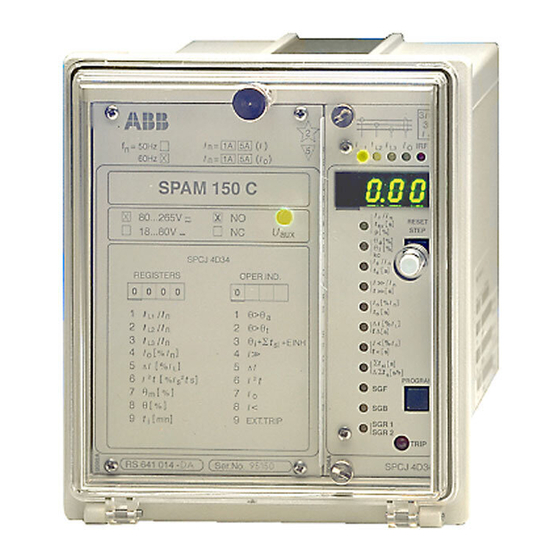
SPAM 150 C
Motor protection relay
User´s manual and Technical description
I
1A
n =
I
n =
1A
80...265V
18...80V –
REGISTERS
0 0 0 0
1
2
3
4
5
6
7
8
9
RS 641
( )
5A
I
f
n = 50Hz
( )
5A
I
60Hz
o
SPAM 150 C
– ~
NO
NC
SPCJ 4D34
OPER.IND.
0
θ
1
>
/
I
I
n
L1
θ
2
>
I
/
I
n
L2
θ
3
I
/
I
i
n
L3
[
]
4
> >
I
%
I
I
o
n
[
]
5
∆
∆
%
I
I
I
L
2
[
2
]
6
2
t
t
I
I
I
%
s
s
θ
[
]
7
m %
I
o
θ
[
]
8
<
%
I
[
]
9
t
min
EXT.TRIP
i
Ser.No.
2
I
I
L1
5
U
aux
θ
θ
kc
I
t
I
t
I
θ
t
a
∆
θ
t ∆
t
Σ
+
t
si EINH
+
I
t
Σ
∆ t
t
SGF
SGB
SGR 1
SGR 2
3
I > >
3
I
I
I
IRF
o
L2
L3
I
/
I
θ
n
RESET
[ ]
t
s
6x
STEP
[ ]
p
%
[ ]
%
a
[ ]
%
i
/
I
s
n
[ ]
s
s
/
>>
I
n
[ ]
>>
s
[
]
I
%
o
n
[ ]
s
o
[
]
%
I
I
L
[ ]
s
[
]
%
<
I
θ
[ ]
<
s
t
[ ]
s
si
Σ
[
]
s/h
s
PROGRAM
TRIP
SPCJ 4D34
Advertisement
Table of Contents

Related Manuals for ABB SPAM 150 C


Summary of Contents for ABB SPAM 150 C
- Page 1 SPAM 150 C Motor protection relay User´s manual and Technical description I > > n = 50Hz 60Hz SPAM 150 C – ~ 80...265V θ RESET 18...80V – STEP θ θ SPCJ 4D34 REGISTERS OPER.IND. >> >> 0 0 0 0 θ...
-
Page 2: Table Of Contents
SPAM 150 C 1MRS 750637-MUM EN Issued 1997-03-05 Motor protection relay Modified 2002-04-24 Version B (replaces 34 SPAM 8 EN1) Checked MK Approved OL Data subject to change without notice Characteristics ........................ 2 Contents Area of application ......................3 Short description of operation ..................3 Connection diagram ....................... -
Page 3: Area Of Application
IRF SELF-SUPERV. CUMULATIVE START-UP COUNTER AND RESTART CONTROL INHIBIT FUNCTION INPUT BS SERIAL PORT SERIAL COMMUNICATION PORT Fig. 1. Protective functions of the motor protection relay type SPAM 150 C. The encircled numbers refer to the ANSI-numbering of protective functions. -
Page 4: Connection Diagram
SGR1/8 SPA-ZC_ Fig. 2. Connection diagram of the motor protection relay SPAM 150 C. The version shown is the one with the normally open trip contact, i.e. with an auxiliary supply and output relay module type SPTU 240R2 or SPTU 48R2. - Page 5 Receiver bus terminal (Rx) and the transmitter bus terminal (Tx) of the bus connection module STALL External stall control input RESTART INHIBIT External restart inhibit control signal LATCHING Latching function of the trip relay Fig. 3. Rear view of relay SPAM 150 C.
- Page 6 The three phase currents are connected to ter- vides a latching function after any trip opera- Connections minals 1-2, 4-5 and 7-8, when the rated current tion. After having latched the output relay must of the secondary circuits is I = 5 A.
-
Page 7: Control Signals Between The Modules
SGB / 6 INTERNAL SIGNAL DIAGRAM RELAY RESET Fig. 4. Control signals between the modules of the motor protection relay SPAM 150 C. The functions of the blocking and starting sig- the measuring relay module. The functions of nals are selected with the switches of switchgroups the different switches are explained in the user´s... -
Page 8: Operation Indicators
= 50Hz yellow LED. If, for instance, the TRIP indi- 60Hz cator glows red, and the indicators I SPAM 150 C at the same time are illuminated, over- – ~ 80...265V θ... - Page 9 To be able to operate the relay needs a secured panel. The primary side of the power supply Power supply auxiliary voltage supply. The power supply module is protected with a fuse, F1, located on and output relay module forms the voltages required by the meas- the PCB of the module.
-
Page 10: Power Supply And Output Relay Module
Technical data Energizing inputs (modified 2002-04) Phase and neutral current inputs, terminals 1-2, 4-5, 7-8, 25-26 1-3, 4-6, 7-9, 25-27 Rated current I Thermal withstand capability - continuously 20 A - for 1 s 500 A 100 A Dynamic current withstand, half-wave value 1250 A 250 A Input impedance... - Page 11 Motor protection relay module SPCJ 4D34 Thermal overload unit Setting of full load current, I 0.5...1.50 x I θ Resolution of current setting 0.01 x I Setting of maximum stall time, t 2.0...120 s Resolution of stall time-setting 0.5 s Cooling time-constant k at zero current (standstill) 1...64 x the heating time constant...
- Page 12 Data transmission Transmission mode Fibre optic serial bus Data code ASCII Selectable data transfer rates 4800 or 9600 Bd Fibre optic bus connection module for supply from host relay - for plastic core cables SPA-ZC 21 BB - for glass fibre cables SPA-ZC 21 MM Fibre optic bus connection module for supply from separate power source...
-
Page 13: Maintenance And Repair
Bus connection module SPA-ZC 17 or SPA-ZC 21 Motor protection relay with make type tripping contact Ordering SPAM 150 C RS 641 014 - AA, CA, DA, FA numbers Motor protection relay with break type tripping contact SPAM 150 C... -
Page 14: Ordering Numbers
Raising frame SPA-ZX 111 SPA-ZX 112 SPA-ZX 113 Example Information 1. Quantity and type designation 15 pcs SPAM 150 C required with 2. Ordering number RS 641 014 - AA order 3. Trip contact N.O. or N.C. Normally open 4. Rated frequency = 50 Hz 5. - Page 15 General characteristics of D-type relay modules User´s manual and Technical description 3 > Relay symbol Fastening screw Self-supervision alarm indicator Indicators for measured (Internal Relay Fault) quantities Display, 1 + 3 digits RESET > STEP t [ ] > Reset / Step push-button >>...
- Page 16 1MRS 750066-MUM EN General characteristics Issued 95-04-12 of D type relay modules Version A (replaces 34 SPC 3 EN1) Checked JH Approved TK Data subject to change without notice Front panel lay-out ......................1 Contents Control push buttons ..................... 3 Display ...........................
- Page 17 The front panel of the relay module contains certain position in the main menu to the corre- Control two push buttons. The RESET / STEP push sponding submenu, for entering the setting push-buttons button is used for resetting operation indicators mode of a certain parameter and together with and for stepping forward or backward in the the STEP push button for storing the set values.
- Page 18 Part of the settings and the selections of the Selector switch- operation characteristic of the relay modules in Switch No Pos. Weigth Value groups SGF, SGB various applications are made with the selector and SGR switchgroups SG_ . The switchgroups are soft- ware based and thus not physically to be found in the hardware of the relay module.
- Page 19 NOTE! During any local man-machine com- any doubt about the settings of the module to be munication over the push buttons and the dis- inserted, the setting values should be read using play on the front panel a five minute time-out a spare relay unit or with the relay trip circuits function is active.
- Page 20 MAIN MENU SUBMENUS STEP 0.5 s PROGRAM 1 s Normal status, display off Current on phase L1 Current on phase L2 Current on phase L3 REV. STEP 0.5 s FWD. STEP 1 s Neutral current Io SUBMENUS Second setting Main setting Actual start value I>...