Table of Contents
Advertisement
Quick Links
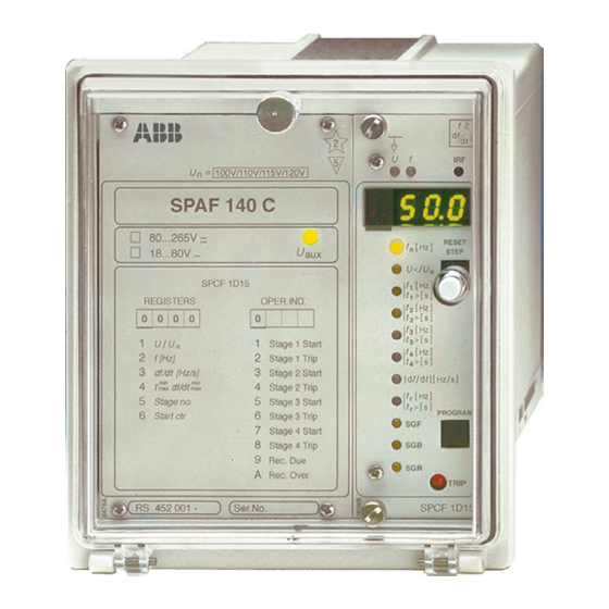
SPAF 140 C
Frequency Relay
User´s manual and Technical description
REGISTERS
0 0 0 0
1
2
3
4
5
6
RS 452 001 -
= 100V/110V/115V/120V
U
n
SPAF 140 C
80...265V ~ –
18...80V –
SPCF 1D15
OPER.IND.
0
1
U
/
U
Stage 1 Start
n
2
f [Hz]
Stage 1 Trip
3
df/dt
[Hz/s]
Stage 2 Start
min
min
4
df/dt
f
Stage 2 Trip
max
max
5
Stage no.
Stage 3 Start
6
Start ctr
Stage 3 Trip
7
Stage 4 Start
8
Stage 4 Trip
9
Rec. Due
A
Rec. Over
Ser.No.
2
U
f
5
f
[
Hz
n
U
aux
U
/
U
<
f
[
Hz
1
t
t
, 1
1
f
[
Hz
2
t
t
, 2
2
f
[
Hz
3
t
t
, 3
3
[
f
Hz
4
t
t
, 4
4
d f d t
/
∆
f
[
Hz
[ ]
t
s
r
SGF
SGB
SGR
SPCF 1D15
>
f
<
d f
>
<
d t
IRF
RESET
]
STEP
n
]
,
[ ]
s
]
,
[ ]
s
]
,
[ ]
s
]
,
[ ]
s
[
/
]
Hz s
]
PROGRAM
TRIP
Advertisement
Chapters
Table of Contents

Related Manuals for ABB SPAF 140 C


Summary of Contents for ABB SPAF 140 C
- Page 1 SPAF 140 C Frequency Relay User´s manual and Technical description > < > < = 100V/110V/115V/120V SPAF 140 C 80...265V ~ – RESET STEP 18...80V – < SPCF 1D15 REGISTERS OPER.IND. 0 0 0 0 Stage 1 Start f [Hz]...
-
Page 2: Table Of Contents
Dimension drawings and mounting................13 Ordering information ....................13 In addition to the general part, the complete manual of the frequency relay SPAF 140 C includes the following relay module descriptions: Combined frequency and rate of change of frequency relay module... -
Page 3: Application
The frequency relay SPAF 140 C is designed to In addition, the frequency relay SPAF 140 C Application be used for the overfrequency/underfrequency can be used for monitoring the power balance protection of generators, motors and other ac in the network and disconnecting parts of the equipment. -
Page 4: Connections
22 11 70 71 72 68 69 85 86 87 88 63 13 14 16 df/dt Fig. 1. Connection diagram for frequency relay SPAF 140 C Auxiliary voltage TS1, TS2 Output relays (heavy-duty) Output relay Self-supervision output relay BS1...BS4 Control signals... -
Page 5: Specification Of Input And Output Terminals
Made in Finland = 63 Fig. 2. Terminals of frequency relay SPAF 140 C Specification of Terminal interval Function input and output terminals 13-14 Phase-to-phase voltage U 100 V 13-15 Not in use 16-17 Not in use 16-18 Not in use... -
Page 6: Operation Indicators
SPCF 1D15 play is identified by yellow LEDs on the front panel. Fig. 3. Front panel of frequency relay SPAF 140 C 4. A permanent fault detected by the self- supervision system is indicated by the IRF 1. The green LED indicator U... -
Page 7: Technical Data (Modified 2001-04)
Technical data Voltage input (modified 2001-04) Rated voltage U (programmable) 100 V (110 V, 115 V, 120 V) Terminal numbers 13-14 Continuous voltage withstand 2 x U Rated burden of voltage input at U <0.5 VA Output contacts Trip contacts Terminal numbers 85-86, 87-88 Rated voltage... - Page 8 Combined frequency and rate of change of frequency relay module SPCF 1D15 - see "Technical data" in the description of the module. Data communication Transmission mode Fibre-optic serial bus Coding ASCII Data transfer rate, selectable 4800 Bd or 9600 Bd Bus connection modules for fibre-optic data transfer - for plastic core cables SPA-ZC 21 BB...
- Page 9 SERIAL PORT (SPA) 47 46 45 23 22 11 70 71 72 68 69 85 86 87 88 63 13 14 16 df/dt Fig. 4. Frequency relay SPAF 140 C used for the protection of a generator and a turbine.
- Page 10 Fig. 5. Setting of the protection stages of frequency relay SPAF 140 C used for the protection of a generator and a turbine. In the case described in the example the switches of the frequency relay SPAF 140 C can be set as follows: Setting of t, relay module SPCF 1D15 Switch- Serial comm.
-
Page 11: Testing
The relay should be subjected to regular tests in As the settings of the relay modules affect the Testing accordance with national regulations and in- operation of the relay (overfrequency/under- structions. The manufacturer recommends an frequency relay) and thus also the test proce- interval of five years between the tests. -
Page 12: Maintenance And Repair
Frequency relay SPAF 140 C without test adapter: RS 452 001-AA, CA Order numbers (modified 98-03) Frequency relay SPAF 140 C with test adapter RTXP 18: RS 452 201-AA, CA The letter combinations of the order number indicate the auxiliary voltage U of the protection relay. -
Page 13: Ordering Information
Raising frame SPA-ZX 111 SPA-ZX 112 SPA-ZX 113 Fig. 12. Dimension and mounting drawings for frequency relay SPAF 140 C. The relay case is made of profile aluminium and The required input and output circuits are con- painted grey. nected to the screw terminals on the rear panel. - Page 15 SPCF 1D15 Combined Frequency and Rate of Change of Frequency Relay Module User´s manual and Technical description > < < > RESET STEP < d f d t Hz s ∆ PROGRAM TRIP SPCF 1D15...
- Page 16 SPCF 1D15 1MRS 750583-MUM EN Issued 1996-11-05 Combined Frequency Modified 2004-03-16 Version D and Rate of Change of Checked PS Approved MÖ Frequency Relay Module Data subject to change without notice Features .......................... 2 Contents Description of operation ....................3 Filtering of energizing inputs ..................
-
Page 17: Description Of Operation
The relay module contains two filters: a lowpass of the filters is to suppress the harmonics of the Description of filter for voltage measurement and a bandpass measured signal. Fig. 1 illustrates harmonics operation filter for frequency measurement. The purpose suppression as a function of frequency. -
Page 18: Underfrequency
Underfrequency A protection stage has the function of an under- The underfrequency stage operates in the same frequency stage, when the setting value is be- way as the overfrequency stage, but starts, when low the rated frequency. The setting value can- the frequency falls below its setting value. -
Page 19: Resetting
Output signals Switchgroups SGR1...SGR9 can be used to link is present, even though the protection stage con- the start or trip signal of any protection stage to trolling the output stays active. the desired outputs SS1...SS4 or TS1...TS4. Resetting of the output relays appears from the Two output operation modes, i.e. - Page 20 Block diagram Hardware U 12 SGF1/3 > < SGF6/1 SGF1/2 & SGR1/x SGF5/1 ∩ SGF1/1 > < SGF6/2 SGR2/x SGF5/2 SGB6/x U< SGF6/3 SGF2/3 > SGB1/x < SGF5/3 SGB2/x SGF2/2 SGB3/x & SGR3/x SGB4/x SGF2/1 > SGB5/x SGF6/4 < SGF5/4 SGR4/x SGF6/5 SGF5/5...
-
Page 21: Front Panel
Front panel Simplified device < > symbol > < Indicators for measured values, Self-supervision voltage U and frequency f alarm indicator Display Indicator for rated frequency setting RESET STEP Indicator for undervoltage setting Reset and display < step push-button Indicator for protection stage 1 settings Indicator for protection stage 2 settings Indicator for protection stage 3 settings Indicator for protection stage 4 settings... -
Page 22: Operation Indicators
Each protection stage has its own red start and trip signal before resetting, the start indicating Operation trip operation code, presented as a number on numbers turn to indicate tripping. When re- indicators the display. In addition, at the right bottom quired, the start indicating numbers can be set corner of the relay module, there is a TRIP in- to remain start indicators (switches SGF1...4/4). -
Page 23: Settings (Modified 2004-03)
The setting values are indicated by the three at the moment. The factory setting is given in Settings digits to the right on the display. A LED indi- brackets. The symbol "//" indicates that the set- (modified 2004-03) cator in front of the setting value symbol on the ting is found in a submenu. - Page 24 The switches SGF1...7, SGB1...6 and SGR1...9 the display. The checksums are found in the Configuration are used for selecting additional functions re- main menu of the relay modules, see "Menu switches quired for a specific application. The numbers chart". The tables also show the factory settings of the switches and the checksum ∑...
- Page 25 Switchgroup SGF6 Selection of the output signal controlling the vated. At the same time the concerned signal TRIP indicator on the front panel. When the starts the recovery function, provided the recov- switch linked to a certain signal is in position 1, ery output is in use (selected with SGR9/_ ).
- Page 26 Switchgroups The switchgroups SGB1...6 are used for confi- is marked with the number of the switch to be SGB1...6 guring the control signals BS1…BS5. The ma- used and the weighting factor of the switch is trix below can be used for the programming. given under the matrix.
- Page 27 Switchgroups The switchgroups SGR1...9 serve for con- TS4, for example, by circling the intersection SGR1...9 figuring the start and trip signals of the protec- of the signal lines. Each intersection is marked tion stages as desired output signals SS1...SS4 with the number of the switch to be used and or TS1...TS4.
-
Page 28: Measured Data
The values measured are indicated by the three can be used, see "Menu chart". The measured Measured data green digits to the right. An exception, how- value being presented on the display is indicated ever, is the measured frequency, for the indica- by the yellow LEDs above the display. - Page 29 Register/ Recorded information STEP The switchgroups SGB1...5 are used for configuring the external control inputs. From this register the TEST mode can be entered. In the TEST mode the trip signals can be activated one by one. The table below shows the signal to be activated plus the corresponding LED indicator.
- Page 30 Menu chart (modified 97-01) Main menu Submenu STEP 0,5 s PROGRAM 1 s =value that can be set in the setting mode Normal status, display off step backwards STEP 0.5 s step forwards STEP 1 s Submenu Phase voltage U Network frequency f 4-digit network frequency f Number of cycles used in...
- Page 31 The procedure for entering a submenu or a set- tail in "General characteristics of D type relay ting mode, the configuration of the module and modules". Below a short guide: the use of the TEST mode are described in de- Desired step or function Push-button Action...
-
Page 32: Technical Data (Modified 2004-03)
Technical data Frequency function (modified 2004-03) Rated frequency 30.00...65.00 Hz Measuring range 20.00...75.00 Hz Setting range 25.00...70.00 Hz Number of cycles to be used for frequency measurement 3...20 cycles ±10 mHz Operation accuracy Minimum voltage to be measured 0.25 x U Rate of change of frequency function Setting range 0.2...10.0 Hz/s... -
Page 33: Serial Communication Parameters
Event codes have been defined for starting and serial bus. An event to be communicated is Serial tripping of the separate protection stages and marked with the factor 1. An event mask is communication for the output signal states. The event codes can formed by adding the weighting factors of the parameters be transmitted to higher system levels over the... - Page 34 Code Event No. represent- Factory ing the event setting Output signal SS1 activated Output signal SS1 reset Output signal SS2 activated Output signal SS2 reset Output signal SS3 activated Output signal SS3 reset Output signal SS4 activated Output signal SS4 reset Event mask V157, factory setting Output signal TS1 activated Output signal TS1 reset...
-
Page 35: Remote Transfer Data (Modified 2004-03)
Remote transfer data In addition to the event codes, input data (I supply failure. (modified 2004-03) data), output data (O data), setting values (S data) memorized data (V data), and some other The push-buttons of the relay module or a com- data can be read from the module over the se- mand given over the serial bus can be used for rial bus. - Page 36 Outputs Status data of protection stages Protection stage/operation Parameter (R) Weighting factor Frequency function of stage 1 started Stage 1 tripped, operate time t 1’ Stage 1 tripped, operate time t df/dt function of stage 1 started Frequency function of stage 2 started Stage 2 tripped, operate time t 2’...
- Page 37 Setting Actual Main sett. Sec. sett. Setting range values (R) values values (R,W,P) (R,W,P) Operate time t , stage 1 S130 0.10...300.00 s **) Operate time t , stage 1 S131 0.10...300.00 s *) Operate time t , stage 2 S132 0.10...300.00 s **) Operate time t...
- Page 38 Measured and Measured value Code Data direction Value recorded parameter values Number of starts, stage 1 0...255 Number of starts, stage 2 0...255 Number of starts, stage 3 0...255 Number of starts, stage 4 0...255 Number of trips, stage 1 0...255 Number of trips, stage 2 0...255...
- Page 39 Control parameters Measured value Code Data Value direction Remote resetting of recorded data V102 1 = resetting Remote control of setting V150 0 = main settings active 1 = second setting active Event mask for stage 1 V153 0...63, see "Event codes" Event mask for stage 2 V154 0...63, see "Event codes"...
-
Page 40: Fault Codes
Once the self-supervision system has detected a number appears on the display of the relay mod- Fault codes permanent fault, the IRF indicator on the front ule. The fault code indicates the fault type and panel of the module is lit and, at the same time, cannot be reset. - Page 41 General characteristics of D-type relay modules User´s manual and Technical description 3 > Relay symbol Fastening screw Self-supervision alarm indicator Indicators for measured (Internal Relay Fault) quantities Display, 1 + 3 digits RESET > STEP t [ ] > Reset / Step push-button >>...
- Page 42 1MRS 750066-MUM EN General characteristics Issued 95-04-12 of D type relay modules Version A (replaces 34 SPC 3 EN1) Checked JH Approved TK Data subject to change without notice Front panel lay-out ......................1 Contents Control push buttons ..................... 3 Display ...........................
-
Page 43: Display
The front panel of the relay module contains certain position in the main menu to the corre- Control two push buttons. The RESET / STEP push sponding submenu, for entering the setting push-buttons button is used for resetting operation indicators mode of a certain parameter and together with and for stepping forward or backward in the the STEP push button for storing the set values. -
Page 44: Settings
Part of the settings and the selections of the Selector switch- operation characteristic of the relay modules in Switch No Pos. Weigth Value groups SGF, SGB various applications are made with the selector and SGR switchgroups SG_ . The switchgroups are soft- ware based and thus not physically to be found in the hardware of the relay module. -
Page 45: Setting Mode
NOTE! During any local man-machine com- any doubt about the settings of the module to be munication over the push buttons and the dis- inserted, the setting values should be read using play on the front panel a five minute time-out a spare relay unit or with the relay trip circuits function is active. - Page 46 MAIN MENU SUBMENUS STEP 0.5 s PROGRAM 1 s Normal status, display off Current on phase L1 Current on phase L2 Current on phase L3 REV. STEP 0.5 s FWD. STEP 1 s Neutral current Io SUBMENUS Second setting Main setting Actual start value I>...
- Page 47 Example 1 Operation in the setting mode. Manual setting for the main setting is 0.80 x I and for the of the main setting of the start current value I> second setting 1.00 x I . The desired main start of an overcurrent relay module.
- Page 48 RESET STEP Set the digit with the STEP push button. 1 1. 0 5 PROGRAM Press the PROGRAM push button to make the decimal point flash. 1 1. 0 5 RESET STEP If needed, move the decimal point with the STEP push button.
- Page 49 Example 2 Operation in the setting mode. Manual setting SGF1/1and SGF1/3 are to be set in position 1. of the main setting of the checksum for the This means that a checksum of 005 should be switchgroup SGF1 of a relay module. The initial the final result.
- Page 50 RESET STEP The switch position is altered to the desired position 1 by pressing the STEP push button once. PROGRAM Using the same procedure the switches SGF 1/ 5 x 1 s 4...8 are called up and, according to the exam- ple, left in position 0.
- Page 51 The parameter values measured at the moment Submenu 2 of register A contains a bus commu- Recorded when a fault occurs or at the trip instant are nication monitor for the SPAbus. If the protec- information recorded in the registers. The recorded data, tion relay, which contains the relay module, is except for some parameters, are set to zero by linked to a system including a contol data...
-
Page 52: Trip Test Function
Register 0 also provides access to a trip test The selected starting or tripping is activated by Trip test function function, which allows the output signals of the simultaneous pressing of the push buttons relay module to be activated one by one. If the STEP and PROGRAM. - Page 53 Example 3 Trip test function. Forced activation of the outputs. Step forward on the display to register 0. RESET STEP n x 1 s 0 0 0 0 Press the PROGRAM push button for about 3 > five seconds until the three green digits to the right.
- Page 54 To proceed to the next position press the PRO- 3 > GRAM push button for about 1 second until the indicator of the second setting starts flash- 0 0 0 0 ing. RESET > STEP PROGRAM t [ ] > >>...
-
Page 55: Fault Codes
A relay module is provided with a multiple of indicator is reset by means of the RESET push Operation separate operation stages, each with its own button of the relay module. An unreset opera- indication operation indicator shown on the display and a tion indicator does not affect the function of the common trip indicator on the lower part of the protection relay module. - Page 56 ABB Oy Distribution Automation P.O.Box 699 FI-65101 Vaasa FINLAND Tel. +358 (0)10 22 11 Fax.+358 (0)10 22 41094 www.abb.com/substationautomation...