
Related Manuals for Mitsubishi Electric PAC-ZC40L-E


Summary of Contents for Mitsubishi Electric PAC-ZC40L-E
- Page 1 ZONE CONTROLLER PAC-ZC40L-E PAC-ZC80L-E PAC-ZC40H-E PAC-ZC80H-E INSTALLATION MANUAL FOR INSTALLER English For safe and correct use, read this manual thoroughly before installing the zone controller.
-
Page 2: Table Of Contents
5. Zone Remote Controller ................14 11. Specifications ...................32 6. Option ......................19 Mitsubishi Electric is not responsible for the failure of locally supplied parts. 1. Safety precautions Before installing the zone controller, make sure you read all the “Safety After installation, perform the test run to ensure normal operation. Then explain precautions”. -
Page 3: Accessory
2. Accessory 2.1. Check the parts (Fig. 2.1.1) The zone controller should be supplied with the following parts. Parts Name Q'ty Zone control interface Indoor unit - zone controller cable (2m) Zone Remote controller <Fig. 2.1.1>... -
Page 4: System
Zone 4 <Fig. 3.2> Fig. 3.2 shows a system example, where no common zone, 4 damper motors, 2 remote controllers and 2 optional temperature sensors are connected. This zone controller is designed for Mitsubishi Electric ducted indoor unit . Symbol Legend Please contact your dealer to find out the model names of applicable units. - Page 5 3. System 3.2. Wiring Diagram a) 24V damper motor model INDOOR UNIT CN105 (RED) Optional Wi-Fi INTERFACE ZONE CONTROL INTERFACE Opt. temp. CN201 sensor 1 CN460 (RED) CN506 (WHT) (RED) CN202 Opt. temp. sensor 2 (RED) TB3M LED1 LED2 Main RC Sub RC TB3AC TB24...
- Page 6 3.3. Component parts Before making your system configuration, confirm the following information for the component parts. Parts Specification Zone controller Make sure to select the correct zone controller from the following 4 models. • Maximum 4 of 24V AC damper motor connecting type : PAC-ZC40L-E • Maximum 8 of 24V AC damper motor connecting type : PAC-ZC80L-E • Maximum 4 of 240V AC damper motor connecting type : PAC-ZC40H-E • Maximum 8 of 240V AC damper motor connecting type : PAC-ZC80H-E Zone remote controller Maximum 2 remote controllers can be connected. 1 remote controller is included in the zone controller.
-
Page 7: Zone Control Interface
4. Zone Control Interface 4.1. Installation 4.1.1 Choosing the zone controller installation location • Do not install the zone controller in outdoor location as it is designed for indoor installation only. (The zone controller circuit board and casing are not waterproof.) • A void locations where the zone contoroller is exposed to direct sunlight or other sources of heat. • S elect a location where easy wiring access to the power source is available. • A void locations where combustible gases may leak, be produced, flow, or accumulate. • S elect a level location that can bear the weight and prevent vibration of the zone contoroller. • A void locations where the zone contoroller is exposed to oil, steam, or sulfuric gas. • D o not install in location that ambient temperature exceeds 60°C and relative humidity exceeds 80%. • Do not install zone control interface on top of the indoor unit. 4.1.2 Installing the zone controller (Fig. - Page 8 4. Zone Control Interface 4.2. Wirings 4.2.1 24V damper motor model [PAC-ZC40L-E / PAC-ZC80L-E] <Routing> All electrical work shall be carried out by a suitably qualified technician. Failure to comply with this could lead to electrocution, fire, and death. All wiring must be conducted according to the national wiring regulations. Connections should be made to the terminals indicated in the following figures depending on the voltage. When terminating cables to terminal bed, please use electrical lugs. Notes: 1. D o not run the low voltage cables through a slot that the high voltage cables go through. 2. D o not bundle power cables (240V) together with other cables. 3. Bundle cables as Fig. 4.2.1 by using clamps.
- Page 9 4. Zone Control Interface <Connecting to indoor unit> ZONE CONTROL INTERFACE Use the accessory cable (2 indoor unit-zone controller cable) for connecting Wifi Indoor CN460 on the zone control interface to CN105 on the indoor controller board. CN201 (RED) CN460 CN506 (WHT) (RED)
- Page 10 4. Zone Control Interface <Damper motors> ZONE CONTROL INTERFACE CN201 (RED) CN460 CN506 Connect the damper motor cable to CN61 to CN68. (WHT) (RED) CN202 The damper motor is powered via TB24. (RED) TB3M Do not connect the 240V AC cable to TB24. LED1 LED2 Refer to the following table to connect the cable to the correct zone.
- Page 11 4. Zone Control Interface 4.2.2 240V damper motor model [PAC-ZC40H-E / PAC-ZC80H-E] <Routing> All electrical work shall be carried out by a suitably qualified technician. Failure to comply with this could lead to electrocution, fire, and death. All wiring must be conducted according to the national wiring regulations. Connections should be made to the terminals indicated in the following figures depending on the voltage. When terminating cables to terminal bed, please use electrical lugs. Notes: 1. D o not run the low voltage cables through a slot that the high voltage cables go through. 2. D o not bundle power cables and damper cables together with other cables. 3. Bundle cables as Fig. 4.2.7 by using clamps. 4. Remote controller cables, sensor cables, and other cables should be segregated by more than 50mm from each other until entry into the zone control inter- face.
- Page 12 4. Zone Control Interface <Indoor unit connection> ZONE CONTROL INTERFACE Use the accessory cable (2 indoor unit-zone controller cable) for connecting Wifi Indoor CN460 on the zone control interface to CN105 on the indoor controller board. CN201 (RED) CN460 CN506 (WHT) (RED) Note:...
- Page 13 4. Zone Control Interface <Damper motors> ZONE CONTROL INTERFACE Connect the damper motor cable to TB6A, TB6B, TB6C and TB6D. CN201 (RED) CN460 CN506 The damper motor is powered via TB3AC. (WHT) (RED) CN202 (RED) Refer to the following table to connect the damper motor to the correct terminal TB3M LED1 LED2...
-
Page 14: Zone Remote Controller
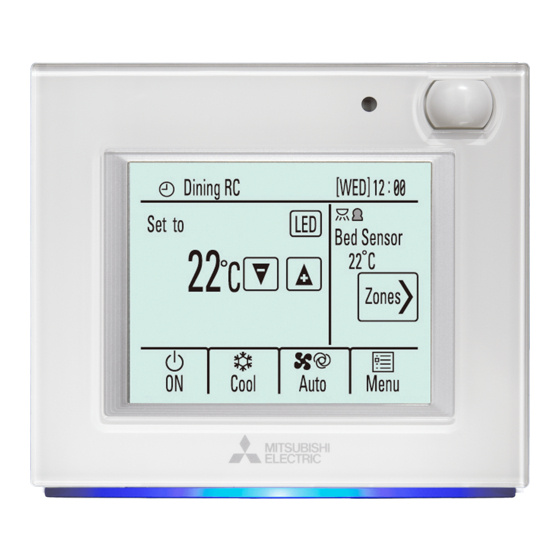
5. Zone Remote Controller 5.1. Main zone remote controller 5.1.1. Installing the zone remote controller Occupancy sensor This remote controller is for the wall installation. It can be installed either on a mounting block or directly on the wall. When performing direct wall installation, ca- bles can be thread through either back or top of the remote controller. l a t (1) Selecting an installation site Wall... - Page 15 5. Zone Remote Controller Occupancy sensor detects occupancy based on the temperature difference be- Brightness sensor tween the occupant and its surroundings. The occupancy sensor is designed to detect the changes in the amount of infrared light emitted from an object in the detection area, including human bodies. l a t The occupancy sensor will not detect occupancy if no movements exist.
- Page 16 5. Zone Remote Controller 3 Prepare the bottom case of the remote controller. Take the following procedure only when performing direct wall installation and running the remote controller cable along the wall. • Cut out the thin-wall part on the cover (indicated with the shaded area in the right figure) with a knife or a nipper. Note: Make sure that the hole edges are smooth and will not damage the wires. Bottom case <Fig. 5.1.5> <Fig. 5.1.6> 4 Install the bottom case. • Remove the sheath as shown in the figure at right, and route the remote con- troller cable behind the bottom case.
- Page 17 5. Zone Remote Controller 6 Connect the remote controller cable to the terminal block on the top case. Connect the cable Connect the remote controller cable to the terminal block. to the terminal block, and insert the cable into the groove. To reduce the risk of electric shock, shorting, or malfunctions, keep wire piec- es and sheath shavings out of the terminal block.
- Page 18 5. Zone Remote Controller 8 Install the front cover on the top case. Wall Two mounting tabs are at the top of the front cover. Hook those two tabs onto the top case, and click the front cover into place. Check that the case is securely installed and not lifted. Important When attaching the front cover to the top case, push it until it they click into place.
- Page 19 6. Option 6.1. Sub zone remote controller ZONE CONTROL INTERFACE 6.1.1. Connect the zone remote controller cable to the zone CN201 (RED) CN460 CN506 control interface (WHT) (RED) CN202 Maximum 2 remote controllers can be connected to TB3M. Connect the remote (RED) controller cable to M1, M2 on the terminal block (TB3M) <Fig.
- Page 20 6. Option 6.2. Temperature sensor ZONE CONTROL INTERFACE Maximum 2 optional temperature sensor(s) are available for the zone controller. CN201 Use only PAC-SE41TS-E. (RED) CN460 CN506 (WHT) (RED) CN202 (RED) 6.2.1. Connecting Opt. temp. sensor (TH1,TH2) TB3M Connect the TH1 cable to the CN201 Connect the TH2 cable to the CN202 LED1 LED2...
- Page 21 6. Option 6.3. Connecting Wi-Fi INTERFACE When connecting Wi-Fi Interface, connect it to CN506 on the zone controller circuit board. ZONE CONTROL INTERFACE Bundle the Wi-Fi cable together with the cable for remote controller and indoor unit- Wifi Indoor zone controller cable using a band. CN201 (RED) CN460...
-
Page 22: Before Test Run
7. Before test run Before turning on the remote controller, first make sure that the remote controller, zone control interface, indoor unit, and outdoor unit have been installed properly accord- ing to the instructions detailed in the respective manuals. Then, turn on the zone control interface and the air conditioner units. 7.1. Wiring check (1) Communication check Check that the LED on zone controller interface Flashing (interval) Turn on the zone control interface and the air conditioner units. After 5 minutes, please confirm that LED of the interface becomes in following state. - Page 23 7. Before test run 7.2. Installing Record Please fill in the table (1) Option setting Option With or without Name Main RC Sub RC Opt. temp. Senror1 Opt. temp. Senror2 Common zone *1 ― (2) Zone setting Zone With or without Name Temp. sensor Outlets *1 Spill zone *2 Zone1 Zone2 Zone3...
-
Page 24: Initial Setting
8. Initial setting This chapter contains information about the settings to be made at the time of in- stallation. Please read the instructions carefully and make the settings accordingly. 8.1. Initial Settings <Fig. 8.1.1> (1) Initial startup settings Before turning on the controller, first make sure that the remote controller, zone control interface, indoor units, and outdoor units have been installed properly ac- cording to the instructions detailed in the respective manuals. - Page 25 8. Initial setting ■Service menu items Item Detail Mandatory Description Setting Default Setup Function setting Use to make the settings for the indoor • Refer to (1) Set menu units and Zone Control Interface from the a) Function setting in page 26 controller. • Refer to "8.3. Function setting of zone control interface". — • Refer to the indoor unit installation manual for the detailed explanation of the...
- Page 26 8. Initial setting (1) Setup menu a) Function setting 1 Select "Unit IC (air conditioning units)" (*1) or "IF (Zone control interface)". *1 The functions may not be available depending on model types. 2 When you select Function number which you want to confirm and touch [Conf] button, the current setting contents are displayed in [Function setting] field. • While monitoring contents for confirm, “Monitoring” is displayed. • When the monitoring is completed, “Completed” is displayed. • When the error happens, “Request denied” is displayed. 3 Select “Function mode number” you want to change the function, and select <Fig.
- Page 27 8. Initial setting c) Name setting Set Zone name 1 Select [Zone name] <Fig. 7.2.12> 2 Touch [Edit] button of zone you want to change the name . <Fig. 7.2.13> 3 Display [List] screen. • When you want to select the name from list,please touch the character string of the candidate. [List] screen has 2 pages.Reshuffing of the page is done by touching [▼][▲]. <Fig. 7.2.14> • When you want to input the upper-case alphabet characters, please touch [ABC] button. The following screen is displayed. The following screen has 2 pages. Reshuffing of the page is done by touching [▼] [▲].
- Page 28 8. Initial setting d) Cool/Heat display <Fig. 7.2.18> e) Telephone number (max. 13 numbers) <Fig. 7.2.19> f) LED color adjustment R (Red), G (Green), B (Blue): “+”···Darken, “–”···Lighten Reset: Restores the de- fault settings for the display color. <Fig. 7.2.20> g) Reset RC <Fig. 7.2.21>...
- Page 29 8. Initial setting (2) Error Menu a) Self check <Fig. 7.2.22> (3) Test Run Mandatory (a) Read the section about Test run in the indoor unit Installation Manual before performing a test run. If indoor unit does not have the function of test run, remote controller will display the error code (0403) after 1 minute.
-
Page 30: Troubleshooting
9. Troubleshooting Number Symptoms Assumed Causes Solutions Ensure that ducts have equal pressure loss. Increase the size of the main duct supply air to the problem area to decrease pressure loss. If duct static pressure is too high, indoor Change function setting Mode 2 to value 2, this will disable low fan speed. unit will go into frost prevention mode. -
Page 31: Supplementary Information
10. Supplementary information Error Code Symptom 4 disit code 2 disit code 5101 Intake sensor error 5102 Pipe (Liquid or 2-phase pipe) sensor error 5103 6840,6843 Indoor/outdoor unit communication error 6842 5701,2503 Drain sensor error 2502 Drain pump error 2500 Forced compressor error 4114 Fan motor error 1503 Freezing/Overheating safeguard operation 1504... -
Page 32: Specifications
11. Specifications Zone control interface Weight PAC-ZC40/80L-E: 2.5kg PAC-ZC40/80H-E: 2.7kg Allowable ambient temperature 0 to 60°C Allowable ambient humidity 80% RH or less External dimensions (W x H x D) 336 x 278x 69mm Zone remote controller Power Source 17–32V DC Receives power from zone control interface via the M-NET transmission (for connection to M-NET only) cable. - Page 36 Installers: Please be sure to put your contact address/telephone number on this manual before handing it to the customer. HEAD OFFICE: TOKYO BLDG., 2-7-3, MARUNOUCHI, CHIYODA-KU, TOKYO 100-8310, JAPAN Authorized representative in EU: MITSUBISHI ELECTRIC EUROPE B.V. HARMAN HOUSE, 1 GEORGE STREET, UXBRIDGE, MIDDLESEX UB8 1QQ, U.K. BH79D480H01...