
Related Manuals for Mitsubishi Electric City Multi PAC-LV11M-J


Summary of Contents for Mitsubishi Electric City Multi PAC-LV11M-J
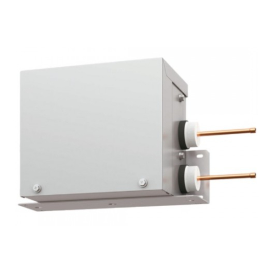
- Page 1 AIR CONDITIONING SYSTEMS CONNECTION KIT PAC-LV11M-J INSTALLATION MANUAL For safe and correct use, please read this installation manual thoroughly before installing the indoor unit.
-
Page 2: Table Of Contents
• Always use an air cleaner, humidifier, electric heater, and other acces- compressor trouble may result. sories specified by Mitsubishi Electric. • Use liquid refrigerant to fill the system. - Ask an authorized technician to install the accessories. Improper installation - If gas refrigerant is used to seal the system, the composition of the refriger- by the user may result in water leakage, electric shock, or fire. -
Page 3: Before Getting Installed
- If dust, dirt, or water gets in the refrigerant cycle, the refrigerant may deteri- • Do not touch the refrigerant pipes during and immediately after opera- orate. tion. - During and immediately after operation, the refrigerant pipes are may be hot 1.3. -
Page 4: Overview Of Units
2. Overview of units 2.1. System outline 2.1.1. System example Connection kit Connection kit Connection kit Connection kit Outdoor unit 2.2. Unit construction Outdoor unit Capacity Indoor unit that Number of units can be Refer to manuals of the outdoor unit. Total system wide connected capacity... -
Page 5: Installation
2.3. Installation 2.3.1. Installing the connection kit Parts to procure locally • Suspension bolts or anchor bolts : W3/8 (M10) • Nut : W3/8 (M10) • Washer : W3/8 (M10) Installing the unit in a ceiling (1) Install the suspension bolts. Wooden structures •... - Page 6 Connect the Connection Kit to the liquid pipe and install it inside the ceiling or on a wall (Do not install in an outdoor location. It may cause a breakdown). Make sure to install the access door on the ceiling. Installation location •...
- Page 7 Installation pattern C (Installing the unit on a wall.) Set the Connection Kit mounting plate as shown below. (Unit: mm) Install the two screws (5 × 10) Mounting plate Anchor nuts (procure locally) Ceiling ANCHOR NUT PITCH SERVICE SPACE Wall 4-Oval holes Wall MIN.50...
-
Page 8: Installing The Refrigerant Piping
2.3.2. Installing the refrigerant piping Check the Connection Kit accessories and parts 1Pipe cover × 2 2Thermistor holder - ø9.52 × 1 3Thermistor holder - ø12.7 × 1 Connect Connection Kit to the liquid pipe. When brazing the refrigerant pipes, be sure to braze, after covering a wet cloth to the insulation pipes of the units in order to prevent it from burning and shrinking by heat. - Page 9 2.3.3. Installing the thermistors Be sure to install the thermistors (gas) supplied with the unit as shown in the illustration. • If the thermistors are not installed, the unit will not operate. If the thermistors are installed incorrectly, the unit will not operate properly.
- Page 10 (2) Insulate the thermistor with the supplied thermal insulation (procure locally). Thermal insulation (procure locally) (3) Cut a 100 mm slit on the top portion of the extension piping pipe cover, and then cover the thermistors with the pipe cover. Pipe cover (procure locally) (4) Wrap the thermal insulation covering the thermistor with tape.
-
Page 11: Wiring Of Main Power Supply And Equipment Capacity
2.3.4. Electrical work 2.3.4.1. Caution (1) Follow local regulations and ordinances for technical standards related to electrical equipment, wiring, and Outdoor unit Connection kit Connection kit specifications of each electric power company. (51) (01) (02) (2) Wiring for control (hereinafter referred to as transmission line) must be situated at least 5 cm from the power source wiring M2 S M2 S... - Page 12 1. Use separate power supplies for the outdoor unit and connection kit. 2. Consider the ambient conditions (ambient temperature, direct sunlight, rain, etc.) when wiring and making connections. 3. The wire size is the minimum value for metal conduit wiring. The power cord size must be 1 rank thinker in consideration of voltage drops.
- Page 13 Examples of UNACCEPTABLE unit configurations (2) Connecting an MA & Contact Termianl Interface using (1) Grouping with CITY MULTI indoor unit IT terminal The connection kit cannot be in the same group to which a CITY MULTI Address: 51 indoor unit belongs because their signal information differs.
- Page 14 Examples of ACCEPTABLE unit configurations (1) Connecting with CITY MULTI outdoor unit A: PURY A: PUHY Address: 51 Address: 51 Address: 01 Address: 01 A-control A-control Address: 52 TB02 A Outdoor unit A Outdoor unit B Connection kit B Connection kit C Indoor unit C Indoor unit D Remote controller...
- Page 15 (4) Grouping with multi-connection kit and RAC indoor units Address: 51 Address: 51 Address: 51 Address: 01 Address: 02 Address: 01 Address: 02 Address: 01 Address: 02 A-control A-control A-control A-control A-control A-control Group Group Group A Outdoor unit A Outdoor unit A Outdoor unit B Connection kit B Connection kit...
- Page 16 2.3.4.4. Wiring Check the Connection Kit accessories and parts 1Cable band × 2 2Thermistor (1) Remove the electrical cover. (2) Install the two cable bands 1. Electrical cover 1Cable band Electrical wire inlet (Power supply, To indoor unit) AT-adapter board Bands Electrical wire inlet (To outdoor unit, From gas thermistor) Terminal block...
-
Page 17: Refrigerant Piping
2.3.5. Refrigerant piping Indoor unit connection example • Connect one connection kit per indoor unit. • Connect the connection kit the liquid pipe. • The thermistor-G (gas) is installed close to the connecting point of the extension piping (gas) for the indoor unit. Connection kit MAX. -
Page 18: Dip Switch Setting
1-10 (897) -*K* series or later (0: OFF, 1: ON) 3. Specifications SPECIFICATIONS OF OPTIONAL PARTS MODEL PAC-LV11M-J Power source Single/220-240 V/50/60 Hz Connectable number of indoor units External finish Hot-dip zinc-coated steel sheet (No external finish) External dimension H×W×D 183 ×... -
Page 19: Outlines And Dimensions
4. Outlines and dimensions... -
Page 20: Wiring Diagram
5. Wiring diagram... -
Page 21: Refrigerant System Diagram
6. Refrigerant system diagram Gas pipe thermistor TH23 Gas pipe Liquid pipe Brazed connections Strainer (#100 mesh) Linear expansion valve Indoor unit Connection kit... -
Page 22: Troubleshooting
7. Troubleshooting 7.1. Test run Caution: Before operating the unit, check that the wiring, piping, and thermistor are installed and that the switches have been set. Refer to the "Test run" section of the indoor units and outdoor unit installation manuals. After installation of an indoor unit, connection kit, and outdoor unit, begin a test run to check water leaks in the connection kit. -
Page 23: Check Methods
7.2. Check methods 1. Component and check points (1) Thermistor Gas pipe thermistor (TH23) Disconnect the connector and measure the resistance between terminals with a tester. (Ambient temperature 10°C - 30°C) Normal Abnormal 4.3kΩ - 9.6kΩ Open or short (Refer to the thermistor characteristic graph below.) 1) Thermistor characteristic graph Low-temperature thermistor Gas pipe thermistor (TH23) - Page 24 1) Summary of linear expansion valve (LEV) operation The LEV is operated by a stepping motor, which operates by receiving a pulse signal from the controller board. The LEV position changes in response to the pulse signal. Controller board and LEV connection 12VDC Brown White...
- Page 25 2) LEV operation Close Open Fully open valve (2000 pulses) No. of pulses Extra tightening (80 - 100 pulse) Valve opening degree When the power is turned on, a pulse signal of 2200 pulses is output (valve closure signal), to bring the valve to position A. When the valve is operating normally, it is free of vibration noise.
-
Page 26: Dip Switch Setting (Factory Setting)
Symptom Checking Criteria Remedy Valve closure fail- To check the LEV on the connection kit, check the indoor unit liquid pipe tempera- Replace the LEV ure (leaky valve) ture that appears on the operation monitor on the outdoor unit's multi control board if the amount of while operating the indoor unit in question in the FAN mode and the other indoor leakage is great. - Page 27 2. Capacity code setting (1) SW2 Dipswitch settings must be made while the unit is stopped. Factory setting = Every switch is set to OFF. The switches are set to correspond to the indoor unit capacity. Model P15, P20 P32, P35 P40, P42 P100 P125...
- Page 28 Please be sure to put the contact address/telephone number on this manual before handing it to the customer. HEAD OFFICE: TOKYO BLDG., 2-7-3, MARUNOUCHI, CHIYODA-KU, TOKYO 100-8310, JAPAN Authorized representative in EU:MITSUBISHI ELECTRIC EUROPE B.V. HARMAN HOUSE, 1 GEORGE STREET, UXBRIDGE, MIDDLESEX UB8 1QQ, U.K. WT06728X03...