Agilent Technologies 5110 ICP-OES Service Manual
Hide thumbs
Also See for 5110 ICP-OES:
- User manual (66 pages) ,
- Site preparation manual (56 pages) ,
- User manual (6 pages)
Table of Contents
Advertisement
Quick Links
Advertisement
Table of Contents

Related Manuals for Agilent Technologies 5110 ICP-OES


Summary of Contents for Agilent Technologies 5110 ICP-OES
- Page 1 Agilent 5110/5100 ICP-OES Service Manual Agilent Restricted...
- Page 2 Restricted Rights Legend procedure, practice, or the like that, if references to Varian. Please note that Varian, Inc. is now part of Agilent Technologies. For not correctly performed or adhered to, U.S. Government Restricted Rights. Software more information, go to could result in personal injury or death.
-
Page 3: Table Of Contents
Content Safety Information Precautions General Handling of Gas Call Qualification Customer Help Guide Functional Issues Performance Issues Spare Parts General Information Specifications Environmental Conditions and Utility Requirements Agilent 5110/5100 ICP-OES system description System overview Instrument layout Instrument configurations Power distribution Instrument control Power On/Off switch indicator Mains Power Module (MPM) Self Check... - Page 4 Content Optics Description Pre optics assembly Polychromator assembly Shutter Pilot mirror Entrance slit Collimating mirror Prism Grating Camera mirror Full illumination LED Fiber Optic Source Camera assembly CCD layout Gas Control Water Control Air Cooling Removal/ Installation, Replacement and Adjustment Tools and Supplies for 5110 instrument Removal hierarchy Instrument covers...
- Page 5 Content Circuit breaker and power socket RF System RF Oscillator RF Current Sensor Igniter SSRF Filter board SSRF Control board RF Power Supply (RFPS) SSRF PSU interface board RFPS cradle Air Cooling Air cooling filter Cooling fan Air cooling flow sensor Plasma interlocks and sensors RF Door interlock switches Plasma sensor...
- Page 6 Content Entrance slit Grating Prism assembly Camera access and removal Optical alignment Pre optics alignment Polychromator and camera alignment Camera image location adjustments Focus Adjustments Camera rotation Argon ratio adjustment Troubleshooting Low Analytical Sensitivity Perform an Instrument test Sensitivity Failure - Analysis Table Low Sensitivity Fault Finding Diagnostics Blocked Nebulizer Blocked Injector Tube...
- Page 7 Content Option Inlet Pressure N2 Inlet Pressure Water Cooling Gauges RF Water Flow Camera Water Flow Water Inlet (°C) Instrument (°C) Air Flow Optics Gauges Polychromator (°C) Polychromator Purge Peltier (°C) Camera Thermal Stabilizer (°C) Camera Water Flow Plasma Gauges RF Water Flow RF Power (kW) Plasma Exhaust (°C)
- Page 8 Content Configure Instrument IP Address Discover a lost IP Address Status diagnostic codes Software error messages Instrument startup constraints Engineer Service Diagnostic screens ICP Expert Diagnostics Typical Event logs (Plasma) Plasma Start up Typical Event log Plasma Extinguished Typical Event log Instrument Error Logs Poly Align Diagnostics Developing a Manganese (Mn) Method...
- Page 9 Water module Peristaltic Pump Wiring Harness/ Looms Air cooling Advanced Valve System (AVS) Parts Index iTroubleshoot/Parts Predict Problem Solving Table 10 Installation Guide (5110 ICP-OES) Introduction Standard installation times Install ICP-OES System Hardware installation Mains connection Gas connection Water chiller connection...
- Page 10 Content Performance test specifications and typical values Analytical Tests Resolution Signal to Background Ratio (SBR/SRBR) Precision 11 Preventative Maintenance Maintenance overview Initial performance test Inspect and clean the system Accessories Sample introduction system Cooling water system Status results table Performance tests Service Engineer comments Preventative Maintenance requirements Resources required...
- Page 11 Safety Information Precautions 12 General 13 Handling of Gas 15 Agilent 5110/5100 ICP-OES Service Manual Agilent Restricted...
-
Page 12: Safety Information Precautions
Safety Information Precautions Precautions Before servicing the various components of the Agilent 5110/5100 ICP- OES, observe the following safety precautions. A WARNING notice denotes a hazard. It calls attention to an operating procedure, practice, or WARNING the like that, if not correctly performed or adhered to, could result in personal injury or death. Do not proceed beyond a WARNING notice until the indicated conditions are fully understood and met. -
Page 13: General
Safety Information General General Warning – High Voltage. To prevent Electric Shock always turn the power off at the main WARNING switch before accessing the interior of the instrument. This is for your own safety as well as to avoid damage to the electronics. When disassembling and reassembling the instrument and parts, be sure to reinstall all screws. - Page 14 Safety Information General Warning – High Radio Frequency Radiation WARNING • The coil around the torch emits high frequency radiation. Even at low power it can cause damage to living tissue, therefore the torch must be shielded in a grounded cage. Never disable the safety features which prevent leakage of High Radio Frequency Radiation via an open door.
-
Page 15: Handling Of Gas
Safety Information Handling of Gas Handling of Gas Warning – Storing Argon Safely WARNING Argon, which is used to create the plasma, is a dangerous gas only if it displaces the air you are breathing or is mishandled in its storage cylinder. Take the following precautions to prevent an explosion or suffocation hazard: •... - Page 16 This page is intentionally left blank. Agilent Restricted Agilent 5110/5100 ICP-OES Service Manual...
- Page 17 Call Qualification Customer Help Guide 18 Agilent 5110/5100 ICP-OES Service Manual Agilent Restricted...
-
Page 18: Call Qualification Customer Help Guide
Call Qualification Customer Help Guide Customer Help Guide The following help guide is designed to support Call Qualification when a Customer phones the Call Centre for help. The guide provides a step by step approach to assist in resolving Customer issues over the phone where possible (Call deflected). - Page 19 Call Qualification Customer Help Guide 8 Ask Customer to light a plasma and check for conditional parameters not in the Red zone. If in the Red zone ask the customer to adjust the relevant input pressure etc. Go to the following sections to assist in diagnosis.
-
Page 20: Performance Issues
Call Qualification Customer Help Guide Performance Issues • Instrument Test Descriptions Performance issues (Marked in Red outline above) can be attributed to Sample Introduction Setup including cleanliness, Wavelength Calibration, Method setup and Applications. Take the following steps to identify the issue. 11 Check tubing for correct installation including pump tube tension and check spraychamber is draining correctly. - Page 21 Call Qualification Customer Help Guide • Instrument control module • Mains Module – Power Supplies • Axial/ Radial pre optics assembly • Left side RF box/ pre optics • Plasma compartment • RF box lower • Gas Control • Polychromator •...
- Page 22 This page is intentionally left blank. Agilent Restricted Agilent 5110/5100 ICP-OES Service Manual...
- Page 23 General Information Specifications 24 Agilent 5110/5100 ICP-OES system description 26 Power distribution 31 Instrument control 33 Power On/Off switch indicator 35 Mains Power Module (MPM) Self Check 36 Instrument status indicator 39 Advanced Valve System (AVS) indicator 40 Plasma RF 41 RF Interlocks 43 Sample introduction 44 Optics 49...
-
Page 24: General Information Specifications
General Information Specifications Specifications Environmental Conditions and Utility Requirements Return to step 8 Agilent 5110 ICP-OES Specification Power requirements Power (kVA) 2.9 kVA Voltage (AC) 200-240V single phase Mains Frequency 50-60Hz Mains Wall socket required (Australia) 15Amp GPO Gas requirements Argon max consumption (L/min) 35.5 L/min... - Page 25 General Information Environmental Conditions and Utility Requirements Agilent 5110 ICP-OES Specification Water cooling maximum inlet pressure (kPa) 400 kPa (58 psi) Water cooling fittings for pipe (Chiller end) 12mm barbs with hose clamps Water cooling fittings for pipe (Instrument end)
-
Page 26: Agilent 5110/5100 Icp-Oes System Description
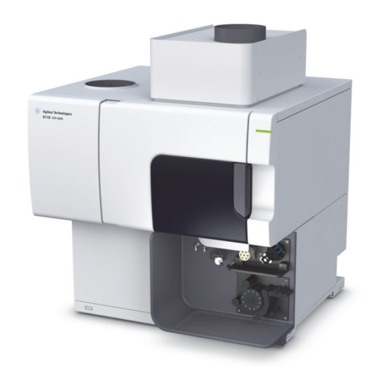
Instrument layout 28 Instrument configurations 30 System overview Figure 1. Agilent 5110 ICP-OES There are 3 models in the Agilent 5110 Inductively Coupled Plasma Optical Emission Spectrometer (ICP-OES). Models include: • Synchronous Vertical Dual View (SVDV) • Vertical Dual View (VDV) •... - Page 27 A quantitative determination is made by the comparison between the radiant intensity of a known concentration of analyte standard and the radiant intensity of the analyte in the samples that are analysed. The fundamental blocks of the Agilent 5110 ICP-OES. The major components of the 5110 include: • Plasma generating system •...
-
Page 28: Instrument Layout
General Information Instrument layout Instrument layout The following pictures outline the location of components within the 5110 instrument. Chimney Air flow sensor Control Electronics and Camera access Pre optics and Beam combiner access Water Module access Water Cooling inlet and RF Oscillator access outlet Water filter... - Page 29 General Information Instrument layout Air inlet and Filter Argon ratio adjustment access Status indicator Torch compartment Cooling fan access RFPS and mains power module access Sample compartment Power connection and circuit breaker Soft Power on switch Makeup gas supply Torch Loader Nebulizer gas supply Torch Spraychamber...
-
Page 30: Instrument Configurations
General Information Instrument configurations Instrument configurations The following standard configurations and options are available with Agilent 5110 ICP-OES models. Configurations Options 5110RV 5110VDV 5110SVDV Radial View Radial view only Vertical Dual View (VDV) Radial and Axial view Synchronous Vertical Dual View (SVDV) -
Page 31: Power Distribution
Power distribution Power distribution The Agilent 5110 ICP-OES instrument is powered via a single phase 20 Amp IEC inlet socket. Operating input voltage is 200-240VAC at 15 Amps maximum (2.9 kVA total maximum power consumption) with nominal running power consumption of 2.2kVA. - Page 32 General Information Power distribution Agilent Restricted Agilent 5110/5100 ICP-OES Service Manual...
-
Page 33: Instrument Control
Instrument control Instrument control The Agilent 5110 ICP-OES instrument control electronics is driven by an Agilent P500 processor (daughter board mounted on the instrument control board). The 5110 communicates to the controlling PC via an ethernet connection consequently has a unique Media Access Code (MAC) address that resides in the P500 processor board. - Page 34 General Information Instrument control Agilent Restricted Agilent 5110/5100 ICP-OES Service Manual...
-
Page 35: Power On/Off Switch Indicator
General Information Power On/Off switch indicator Power On/Off switch indicator Return to step 2 The instrument power On/Off switch is located at the bottom left hand side of the instrument and the switch LED provides instrument status feedback as indicated in the table below. On/Off Switch Instrument state (when main instrument power switch is on) Green LED... -
Page 36: Mains Power Module (Mpm) Self Check
General Information Mains Power Module (MPM) Self Check Mains Power Module (MPM) Self Check Following is a detailed step by step description of the Mains Power Module start up and shutdown sequence. Initial This is the initial step of the MPM start-up sequence and is performed when power is first connected to the instrument. -
Page 37: Rf Power Supply Relay
General Information Mains Power Module (MPM) Self Check If there is high current detected (over 200mA), it will stay in a reset loop. This means the triacs are faulty, can’t proceed with testing. If the fault is downstream (outside) the MPM, disconnecting the fan or blower will enable the MPM to get past this step. -
Page 38: Shutdown
General Information Mains Power Module (MPM) Self Check In this step of the MPM start-up sequence, all instrument control relays and output channels are enabled and the instrument is considered to be “on”. Flash at 2Hz in “on” state if open circuit was detected on heater and blower checks. In addition to the above steps on the MPM start-up sequence, there is one further step entitled “Shutdown”. -
Page 39: Instrument Status Indicator
General Information Instrument status indicator Instrument status indicator Return to step 2 The instrument status LED indicator is located at the top right hand side of the instrument and provides the following LED color combination feedback depending on instrument status. Status LED Color Instrument State None (off) -
Page 40: Advanced Valve System (Avs) Indicator
General Information Advanced Valve System (AVS) indicator Advanced Valve System (AVS) indicator The AVS status LED indicator is located on the AVS Accessory plate (if installed), between the switching valve and the Pump and provides the following LED color combination feedback depending on Accessory status. -
Page 41: Plasma Rf
Figure 2. Agilent 5110 RF Oscillator and torch compartment The Agilent 5110 ICP-OES Solid State Radio Frequency (SSRF) generator forms the heart of the plasma generation system. The energy produced from the SSRF generator is directed into a suitable gas, in this case argon. - Page 42 General Information Plasma RF Figure 3. SSRF Generator and control circuits block diagram The RF power levels are set through a combination of varying the DC supply voltage from the RF power supply (RFPS) and adjusting the FET DC bias voltage using PWM from the SSRF control processor.
-
Page 43: Rf Interlocks
General Information RF Interlocks RF Interlocks There are a number of interlocks throughout the 5110 instrument required to maintain a safe working environment and also to prevent possible instrument damage. Plasma ignition is governed by 3 interlocks as identified in circuit above. Each of these interlocks is monitored continuously independent to the plasma being on or off to ensure interlock integrity is maintained at all times. -
Page 44: Sample Introduction
General Information Sample introduction Sample introduction Section Contents: Description 44 Nebulizers 45 Spraychambers 47 Description The sample introduction system conditions and transports the sample into the plasma. The sample introduction system includes: Torch, Spraychamber, Nebulizer, Peristaltic pump and associated tubing. Figure 4. -
Page 45: Nebulizers
• Argon Humidifier Accessory (AHA) Figure 5. Sample introduction system (violet) block diagram including options (green) Nebulizers Two basic types of nebulizers can be used with the Agilent 5110 ICP-OES instruments to form an aerosol. Agilent 5110/5100 ICP-OES Service Manual Agilent Restricted... -
Page 46: Glass Concentric Nebulizer
• Free uptake: 2mL/min • Gas flow: 0.7L/min at 30psi Ultrasonic An ultrasonic nebulizer is offered with the Agilent 5110 ICP-OES instruments as an accessory. A typical ultrasonic nebulizer uses the vibration of a piezo-electric transducer to form an aerosol. Agilent Restricted... -
Page 47: Spraychambers
The design transports a fine spray to the torch, while larger droplets coalesce, fall to the bottom and are removed through the spraychamber drain by the pump and pump tubing. Typical spraychambers used with the Agilent 5110 ICP-OES instruments include: • Glass single-pass cyclone (Cyclonic) •... - Page 48 General Information Spraychambers Figure 7. Double pass glass cyclonic spraychamber All spraychambers above are suitable for use with aqueous and organic solvents. NOTE Agilent Restricted Agilent 5110/5100 ICP-OES Service Manual...
-
Page 49: Optics
General Information Optics Optics Section Contents: Description 49 Pre optics assembly 51 Polychromator assembly 52 Camera assembly 54 Description The 5110 spectrometer optical system features a temperature controlled purged optics assembly allowing analysis over a full range of wavelengths from 166.798 nm to 784.307 nm. The optical system of the Agilent 5110 spectrometer accepts light radiated from the plasma and separates it into discrete wavelengths. - Page 50 General Information Description Figure 8. Agilent 5110 Synchronous Vertical Dual View optical layout The pre-optics assembly gathers the incident light from the plasma and transfers the light into the polychromator assembly. The pre-optics assembly is located behind the RF box assembly. It contains a stepper motor driven flat scanning mirror for the radial view aswell as fixed flat and toric mirrors for the Axial view.
-
Page 51: Pre Optics Assembly
General Information Pre optics assembly There are two heater pads fixed to the outer polychromator box. The heat from the pads and outer box is transferred to the polychromator casting across an air gap. The air gap acts as a low pass filter that attenuates any sharp temperature variations that occur between ambient room temperature, the heater box and the casting. -
Page 52: Polychromator Assembly
The echelle polychromator assembly consists of: • Pilot mirror • Entrance slit • Collimating mirror • CaF prism • Echelle ruled grating • Camera mirror • LED fibre optic full illumination source Figure 10. Agilent 5110 ICP-OES Polychromator Agilent Restricted Agilent 5110/5100 ICP-OES Service Manual... -
Page 53: Shutter
Shutter For the Agilent 5110 ICP-OES instruments, the collected incident light from the pre-optics assembly passes through a mechanical shutter. This shutter is solenoid driven and controlled through the camera control board. -
Page 54: Camera Mirror
Camera assembly The Agilent 5110 ICP-OES instrument camera assembly is an application specific, solid-state detector, designed for use in the Agilent ICP-OES echelle polychromator. It is a peltier cooled, charge-coupled device, (CCD), which is made up of 70,908 pixels spread across 70 non- linear arrays. -
Page 55: Ccd Layout
General Information Camera assembly Figure 12. Agilent 5110 ICP-OES instrument camera assembly The Agilent 5110 ICP-OES instrument camera assembly consists of: • Charge Coupled Device (CCD) • Camera bus and bias resistors • Water cooled peltier with temperature sensor CCD layout The CCD is 20 mm wide by 15 mm high. -
Page 56: Gas Control
Figure 13. 3 Gas options available The polychromator of the Agilent 5110 ICP-OES spectrometer default purge gas is argon but can be purged with Nitrogen if the optional 3 gas purge option is installed. The gas purge options are fitted in the gas control manifold and are customer installable. - Page 57 General Information Gas Control Agilent 5110/5100 ICP-OES Service Manual Agilent Restricted...
-
Page 58: Water Control
General Information Water Control Water Control The Agilent 5110 water management system is required to cool the RF work coil, axial pre optics cone, RF oscillator module and camera assembly. The control is managed through the water control module which is located next to the gas control system on the right hand side of the instrument. - Page 59 General Information Water Control Agilent 5110/5100 ICP-OES Service Manual Agilent Restricted...
-
Page 60: Air Cooling
General Information Air Cooling Air Cooling Air cooling forms part of the instrument thermal extraction system to remove excess heat and maintain a stable instrument operating temperature. Primary heat extraction is for the RF system with a plasma running. ~1400 Watts of thermal energy is ducted from the instrument through the exhaust chimney. -
Page 61: Removal/ Installation, Replacement And Adjustment
Removal/ Installation, Replacement and Adjustment Tools and Supplies for 5110 instrument 62 Removal hierarchy 65 Instrument covers 67 Sample introduction 74 Instrument Electronics 85 RF System 89 Air Cooling 101 Plasma interlocks and sensors 103 Gas System 106 Water system 111 Optics System 114 Agilent 5110/5100 ICP-OES Service Manual Agilent Restricted... -
Page 62: Tools And Supplies For 5110 Instrument
Removal/ Installation, Replacement and Adjustment Tools and Supplies for 5110 instrument Tools and Supplies for 5110 instrument Tool Part Number Where used Safety glasses Protective laboratory gloves Paper towels Laboratory tissues Plastic tray Items in bold required for installation T10 TORX Driver 5182-3466 Top Covers, Power socket, Torch interlock T20 TORX Driver... - Page 63 Removal/ Installation, Replacement and Adjustment Tools and Supplies for 5110 instrument Tool Part Number Where used Adjustable wrench (200mm) Water fittings, General Flow Meter Gas flows Digital Multimeter Fault Finding ESD Strap 7910031300 PCA handling Plastic tubing cutter 8710-1930 Hoses Blades for plastic tube cutter 8710-1931 Mirror...
- Page 64 Removal/ Installation, Replacement and Adjustment Tools and Supplies for 5110 instrument When working on the 5110 ICP-OES, make sure to turn OFF the power of the 5110 ICP-OES WARNING beforehand. Starting work without turning off the power is extremely dangerous, as you may come in contact with high voltage.
-
Page 65: Removal Hierarchy
Removal/ Installation, Replacement and Adjustment Removal hierarchy Removal hierarchy The following hierachy shows sequence required for removal of covers and assemblies to allow access to and adjustment of components. Find the assembly that is to be replaced and work back from there to determine what covers and other parts need to be removed to access the assembly in question. - Page 66 Removal/ Installation, Replacement and Adjustment Removal hierarchy Agilent Restricted Agilent 5110/5100 ICP-OES Service Manual...
-
Page 67: Instrument Covers
Removal/ Installation, Replacement and Adjustment Instrument covers Instrument covers Section Contents: Left hand side cover 67 Left hand top cover 68 Chimney 69 Right hand side cover 70 Top right hand cover 71 Front left lower cover 73 Torch compartment door 73 Left hand side cover 1 Loosen 2 torx 20 screws. -
Page 68: Left Hand Top Cover
Removal/ Installation, Replacement and Adjustment Left hand top cover Left hand top cover 1 Loosen cover locking mechanism. 2 Pull mechanism out. 3 Remove 3 torx 10 screws. Agilent Restricted Agilent 5110/5100 ICP-OES Service Manual... -
Page 69: Chimney
Removal/ Installation, Replacement and Adjustment Chimney 4 Lift top cover, push back (to release rear tabs) and remove cover. Chimney 1 Remove 2 white plugs to reveal screws. 2 Loosen torx 20 screw (Left hand). 3 Loosen torx 20 screw (right hand). 4 Push chimney back and up to release from front tabs. -
Page 70: Right Hand Side Cover
Removal/ Installation, Replacement and Adjustment Right hand side cover 5 Pull chimney forward to release from rear tabs. Right hand side cover 1 Pull utilities cover to the left to remove from locking pins. 2 Loosen rear torx 20 screw. 3 Loosen front torx 20 screws. -
Page 71: Top Right Hand Cover
Removal/ Installation, Replacement and Adjustment Top right hand cover 4 Slide cover out and pull down to release tabs. Top right hand cover 1 Remove torx 20 control box screw and swing control box out. 2 Loosen cover locking mechanism torx 20 screw. 3 Pull locking mechanism out (to the right). - Page 72 Removal/ Installation, Replacement and Adjustment Top right hand cover 4 Remove torx 10 screw from front right of top cover. 5 Remove torx 10 screw from front left of top cover. 6 Remove torx 10 screw from rear left of top cover. 7 Lift top cover, push to rear of instrument to separate rear locking tabs and then remove by sliding cover towards the right of the instrument.
-
Page 73: Front Left Lower Cover
Removal/ Installation, Replacement and Adjustment Front left lower cover Front left lower cover 1 Loosen screw in sample compartment. 2 Loosen screw at left front of instrument. 3 Slide cover out and up to release tabs at bottom of cover. Torch compartment door 1 To remove door slide up and out. -
Page 74: Sample Introduction
Advanced Valve System (AVS) 82 Torch The Agilent 5110 ICP-OES is supplied with a pre aligned bonded torch for sample analysis. Demountable torches are available as an option. The torch is installed with one action using the torch loader which removes the need to connect and disconnect gas and sample tubes as well as providing repeatable positioning of the plasma bullet in the optical path. -
Page 75: Torch Loader Micro Switch
Removal/ Installation, Replacement and Adjustment Torch loader micro switch 2 For demountable torches - To demount the “outer tube set” remove ring by easing up by hand or with screwdriver or similar. 3 Pull the glass outer tube set from the holder being careful not to break the glass injector. 4 To replace “tube set”... - Page 76 Removal/ Installation, Replacement and Adjustment Torch loader micro switch 1 Remove 2 hex head screws with 5mm hex driver. 2 Slide plate away from instrument to expose micro switch interlock. 3 Remove torx 10 screw. 4 Disconnect loom and replace switch as required. Be sure to tuck loom out of the way during reassembly.
-
Page 77: Torch Loader
Removal/ Installation, Replacement and Adjustment Torch loader 5 When re positioning micro switch ensure molded pin on micro switch locates correctly into hole of mount before tightening screw. Torch loader 1 Remove 3 torx 20 screws and remove handle. 2 Remove 2 x 5mm hex screws and remove plate. 3 Remove 3 x 5mm hex screws and remove micro switch as per torch loader micro switch section. - Page 78 Removal/ Installation, Replacement and Adjustment Torch loader 5 Remove both gas fittings using 3mm hex key. 6 Remove 4 torx 20 screws with insulators. 7 Remove 2 torx 20 screws and move ignitor holder out of the way. 8 Pull casting forward to release from 2 rear locating dowel pins and pull up and out. (If tight to remove refer to next step).
- Page 79 Removal/ Installation, Replacement and Adjustment Torch loader 9 If Torch Loader (as shown in previous picture) is tight to move or align use a spanner or similar tool resting on a socket (as shown) to raise RF box slightly. This will allow some freedom to remove and replace the loader.
-
Page 80: Axial Cone Cooling Interface
Removal/ Installation, Replacement and Adjustment Axial Cone Cooling interface Axial Cone Cooling interface 1 Switch off water supply. 2 Remove 3 Torx 20 screws that secure the interface. 3 Remove interface from studs. 4 Using pliers unscrew knurled nuts that hold tubing to nipple. 5 Remove both tubes from nipples. -
Page 81: Peristaltic Pump
Removal/ Installation, Replacement and Adjustment Peristaltic Pump 6 Replace and reconnect hoses. Check for leaks before securing interface. Peristaltic Pump 1 The peristaltic pump is part of the sample introduction system providing sample uptake flow and waste flow. There are both 3 and 5 channel pumps available depending on the configuration. -
Page 82: Advanced Valve System (Avs)
Removal/ Installation, Replacement and Adjustment Advanced Valve System (AVS) Advanced Valve System (AVS) The Advanced Valve System is an optional accessory available to increase speed of sample throughput and reduce sample inject volume. There are 3 types available, 4 port, 6 port and 7 port. All versions remove and install in the following manner. -
Page 83: Switching Valve Head
Removal/ Installation, Replacement and Adjustment Advanced Valve System (AVS) Before removing Bubble inject tubing turn off incoming Argon gas supply. NOTE If instrument is to be operated with Bubble inject supply disconnected, seal end of tubing with joiner and blanking plug. 4 Remove Argon Bubble inject line by pressing black ring and pulling tubing in the direction of the arrow. -
Page 84: Changing Valve Head Type
Removal/ Installation, Replacement and Adjustment Advanced Valve System (AVS) 1 To remove and replace Valve Head loosen Hex screw with tool. 2 Pull valve head away from instrument. 3 Replacement is the reverse of removal. Changing Valve Head Type 1 If Head type is to be changed from 6/7 port to 4 port or vice versa go to Service Diagnostics “Switching Valve”... -
Page 85: Instrument Electronics
Instrument Electronics Instrument Electronics The Agilent 5110 ICP-OES communicates to the controlling PC via an ethernet connection. Each instrument has a unique Media Access Code (MAC) address that resides in the P500 board. If the P500 board is replaced the MAC address will also change to a new address. -
Page 86: Instrument Control Module
Removal/ Installation, Replacement and Adjustment Instrument Control module Instrument Control module 1 To replace any of the Printed Circuit boards from the Instrument control module follow the below hierachy. 2 To disconnect ribbon cables push up tabs on either side of the connector to release ribbon. Loosen 2 torx screws and remove outer cover of control module. -
Page 87: Mains Power Module
Removal/ Installation, Replacement and Adjustment Mains Power Module Mains Power Module The mains module distributes power to all parts of the instrument and contains a 24 Volt switch mode power supply that feeds the distribution PCA within the module. There are no user serviceable parts within the module. Any failure will require the replacement of the entire module. -
Page 88: Mains Filter
Removal/ Installation, Replacement and Adjustment Mains Filter Mains Filter This process assumes Mains input module has been removed. 1 To remove Mains filter remove 2 torx 20 screws, disconnect wires and remove from chassis. Circuit breaker and power socket Power circuit breaker and power socket can also be accessed with Mains module removed. 1 Remove 2 torx 10 screws from IEC socket. -
Page 89: Rf System
Removal/ Installation, Replacement and Adjustment RF System RF System Section Contents: RF Oscillator 89 RF Current Sensor 95 Igniter 96 SSRF Filter board 97 SSRF Control board 98 RF Power Supply (RFPS) 98 SSRF PSU interface board 99 RFPS cradle 99 RF Oscillator The RF oscillator module provides the high power RF field as the excitation source for generating a plasma. - Page 90 Removal/ Installation, Replacement and Adjustment RF Oscillator 1 Remove Torch by pulling down and out. 2 Remove 4 torx screws from RF Oscillator cover and remove cover. 3 Loosen blue fibre optic sensor screw by rotating thimble anticlockwise and remove fibre optic cable from receptacle.
- Page 91 Removal/ Installation, Replacement and Adjustment RF Oscillator 6 Using open ended wrench disconnect clear water hose only from assembly body. Ensure water drips onto paper towel and not into assembly. 7 Loosen 2 rear torx 20 screws in slots (blue) and remove 2 front torx 20 screws (yellow). 8 Pull on handle to disengage plug from socket and carefully remove module from RF box assembly.
- Page 92 Removal/ Installation, Replacement and Adjustment RF Oscillator 10 When assembling RF Oscillator module into instrument ensure the handle pushes the connector home before attempting to tighten screws. 11 Position SSRF module to align work coil laterally (front to back and yellow arrow) with torch before securing SSRF screws.
- Page 93 Removal/ Installation, Replacement and Adjustment RF Oscillator Before securing front cover, install coil, turn on water supply and in “Dashboard” Tab Click “RF NOTE Water Flow” On button to enable RF Oscillator water solenoid and check that there are no water leaks.
- Page 94 Removal/ Installation, Replacement and Adjustment RF Oscillator 20 Go to Plasma diagnostics page, Calibration tab. 21 Click on “Read from RAM” to load current settings. 22 Enter the Bias offset number into “Value” column next to “Bias_offset_V” as displayed on the serial number label for the replacement oscillator.
-
Page 95: Rf Current Sensor
Removal/ Installation, Replacement and Adjustment RF Current Sensor 26 Go to the Plasma diagnostics page, Sequence tab. 27 Click on “Read from RAM” to load current settings. 28 Check the Value of “Ig_PS_I” and change to 3.5 if it is any other number. 29 Click on “Send to RAM”. -
Page 96: Igniter
Removal/ Installation, Replacement and Adjustment Igniter 4 Loosen coil nuts and remove coil. 5 Remove nut and insulator that secures current sensor to SSRF body. (Do not overtighten this nut when reassembling!) 6 Slide current sensor away from coil shaft and replace as required. The sensor fits tightly on a morse taper and may need a gentle tap to remove. -
Page 97: Ssrf Filter Board
Removal/ Installation, Replacement and Adjustment SSRF Filter board 1 Remove Igniter high voltage cable from igniter body. Remove 2 torx 20 screws. Unplug igniter and replace. 2 Reassemble Igniter into RF box. Ensure that high voltage connector is pressed completely home. -
Page 98: Ssrf Control Board
Removal/ Installation, Replacement and Adjustment SSRF Control board SSRF Control board The SSRF control board regulates RF Power to the Coil via the SSRF filters and RF Oscillator and communicates with instrument control via an RS485 SLIP bus. The board includes a Pulse Width Modulator (PWM) drive control for the RF Oscillator (FET bias) with feedback circuits for current and voltage control. -
Page 99: Ssrf Psu Interface Board
Removal/ Installation, Replacement and Adjustment SSRF PSU interface board The module is located in the lower left hand front of the instrument and is accessible via removal of the lower left hand front cover. 1 To remove the RF power supply remove the torx 20 screw and remove the holding bracket. 2 Pull the power supply forward to disengage with the socket and remove from the housing. - Page 100 Removal/ Installation, Replacement and Adjustment RFPS cradle 1 To remove RFPS cradle, remove torx 20 screws from within chassis floor. Remove rear panel torx screw, disconnect cables and pull forward. Agilent Restricted Agilent 5110/5100 ICP-OES Service Manual...
-
Page 101: Air Cooling
Removal/ Installation, Replacement and Adjustment Air Cooling Air Cooling Section Contents: Air cooling filter 101 Cooling fan 101 Air cooling flow sensor 102 Air cooling filter The cooling fan is mounted on the left front side of the instrument and provides air cooling for the Plasma and RF power supply. -
Page 102: Air Cooling Flow Sensor
Removal/ Installation, Replacement and Adjustment Air cooling flow sensor 1 To remove fan assembly remove single torx screw and remove cover by lifting up and dislocating tabs from base assembly. 2 Remove 3 rawl screws (screws with rubber cushion). 3 Disconnect wires from capacitor and remove assembly. Replacement is reversal of disassembly. -
Page 103: Plasma Interlocks And Sensors
Removal/ Installation, Replacement and Adjustment Plasma interlocks and sensors Plasma interlocks and sensors Section Contents: RF Door interlock switches 103 Plasma sensor 104 RF1 (SSRF exhaust) temperature sensor 105 RF2 (Plasma exhaust) temperature sensor 105 RF Door interlock switches 1 Disconnect loom to micro switch assembly. 2 Remove 1 x 7mm nut that secures assembly to RF box. -
Page 104: Plasma Sensor
Removal/ Installation, Replacement and Adjustment Plasma sensor 4 When replacing assembly align micro switch assembly into slot and tighten front nut loosely. 5 Adjust microswitch assembly to activate when door closes and tighten rear 7mm nut and front nut of assembly. Plasma sensor 1 Plasma sensor is mounted into the left side of the pre optics casting above the RF box. -
Page 105: Rf1 (Ssrf Exhaust) Temperature Sensor
Removal/ Installation, Replacement and Adjustment RF1 (SSRF exhaust) temperature sensor 3 The plasma sense wiring harness also includes temperature sensor connectors RF1 and RF2 that will need to be replaced at the same time. RF1 (SSRF exhaust) temperature sensor 1 Unscrew torx 20 screw from sensor, unplug and replace as required. Temperature sensor wiring harness is part of the plasma sensor harness. -
Page 106: Gas System
Removal/ Installation, Replacement and Adjustment Gas System Gas System The Agilent 5110 Gas distribution and control is managed by the Gas Control Module that communicates via a high speed SLIP bus with the Instrument Control board and is mounted in the right hand side of the instrument as shown. - Page 107 Removal/ Installation, Replacement and Adjustment Gas control module 3 Disconnect 8 quick connect hoses and cables and remove module completely. If AVS is installed disconnect tubing from AVS regulator aswell (as denoted by red arrow above). NOTE 4 Replace module and reconnect 6 quick connect hoses ensuring that the labels on the hoses match the color coded quick connect fittings.
-
Page 108: Gas Option
Removal/ Installation, Replacement and Adjustment Gas Option Numbers on colors represent resistor color codes and have no relevance. NOTE 5 Connect 24V power and RJ45 control cables. 6 Slide Module back into chassis and secure 4 torx screws. Reconnect gas filter ensuring correct orientation with the arrow facing up. -
Page 109: Gas Filter
Removal/ Installation, Replacement and Adjustment Gas Filter 1 To change gas block option remove 4 hex screws. 2 Replace module with any of the 3 options ensuring that 3 O ring seals are seated correctly before locating module. 3 Tighten 4 hex screws to secure assembly. Note position of shorter screw (red arrow). Gas Filter Agilent 5110/5100 ICP-OES Service Manual Agilent Restricted... - Page 110 Removal/ Installation, Replacement and Adjustment Gas Filter 1 To remove Gas filter slide out from spring holder. 2 Press quick connect rim in direction of red arrow and pull tubing out (yellow) for both top and bottom fitting. 3 When replacing filter note direction of flow. Agilent Restricted Agilent 5110/5100 ICP-OES Service Manual...
-
Page 111: Water System
Removal/ Installation, Replacement and Adjustment Water system Water system The Agilent 5110 water management system is required to cool the RF work coil, axial pre optics cone, RF oscillator module and camera assembly. The control is managed through the water control module which is located next to the Gas control system on the right hand side of the instrument. -
Page 112: Ssrf Water Inlet Temperature Sensor
Removal/ Installation, Replacement and Adjustment SSRF water inlet temperature sensor 3 Disconnect yellow and blue hoses and cable. 4 Disconnect green and red hoses using wrench. 5 Replace and reconnect module as required. SSRF water inlet temperature sensor The water inlet temperature sensor is located inside the lower part of the instrument and can be accessed via the lower front cover. -
Page 113: Water Filter
Removal/ Installation, Replacement and Adjustment Water filter Water filter 1 To access water filter remove nut with 17mm open ended wrench. 2 Remove filter and clean as required. Before securing water module into chassis switch on water cooling and ensure there are no CAUTION water leaks. -
Page 114: Optics System
Removal/ Installation, Replacement and Adjustment Optics System Optics System Procedures described in this section must be followed when servicing an optics chassis. All CAUTION of these points should be read and understood. Failure to do so may result in permanent damage to the instrument: All optical mirror surfaces are MgF coated. -
Page 115: Axial Window
Removal/ Installation, Replacement and Adjustment Pre Optics System Axial window 1 Remove the 3 skimmer cone nuts and remove skimmer cone. 2 Withdraw axial window. 3 Unscrew window collet from assembly and replace or clean window as required. Agilent 5110/5100 ICP-OES Service Manual Agilent Restricted... -
Page 116: Radial Window
Removal/ Installation, Replacement and Adjustment Pre Optics System Remove highlit section as window can be cleaned. The Axial window is very likely to be NOTE contaminated if the Spraychamber pump tube is connected in reverse allowing contaminant to pass through plasma and deposit on window. The Axial window may also be more easily contaminated if the drain tube is not pumping correctly allowing a buildup of waste in the Spraychamber. -
Page 117: Mirror Axial M1
Removal/ Installation, Replacement and Adjustment Pre Optics System 4 Unscrew retaining ring (anticlockwise). Do not squeeze ring while attempting to undo it as this will cause ring to jam in holder. NOTE 5 Remove window. 6 Clean or replace and reassemble as required. Mirror axial M1 1 To replace Mirror Axial M1 remove 6 torx screws to remove access plate and slide in new mirrors. -
Page 118: Mirror Axial M2
Removal/ Installation, Replacement and Adjustment Pre Optics System 2 Ensure the mirror is assembled in the correct orientation with reflective side face down as indicated by red dot (Glass edges should be visible if correctly positioned). There is no adjustment required. 3 Ensure that mirror locates correctly into position otherwise mirror will break when top plate screws are tightened. -
Page 119: Mirror Axial M3
Removal/ Installation, Replacement and Adjustment Pre Optics System 3 Assemble replacement mirror in position ensuring that nut holding spring in place does not over compress spring. To ensure correct spring tension of the mirror on the kinematic mount the thickness of a piece NOTE of paper should be able to be slid between at least one of the spring coils when nut is tightened to correct tension. -
Page 120: Mirror Radial M1
Removal/ Installation, Replacement and Adjustment Pre Optics System 1 To replace Axial mirror M3 remove 6 torx screws and slide mirror into place with non reflective side facing up. (Glass edges should be visible if correctly positioned). There is no adjustment required. -
Page 121: Mirror Radial M2
Removal/ Installation, Replacement and Adjustment Pre Optics System 3 Remove 4 torx screws from motor. 4 Disconnect motor and remove from casting. Mirror radial M2 1 Remove pre optics side cover. 2 Remove torx screw holding mirror to casting and remove mirror assembly (including bracket) from casting. -
Page 122: Beam Combiner And Pca Board
Removal/ Installation, Replacement and Adjustment Pre Optics System Beam combiner and PCA board The beam combiner assembly is factory set and aligned therefore the entire assembly must CAUTION be replaced. If the mirror assembly is removed from the motor shaft the assembly alignment will be lost. -
Page 123: Thermal Stabilizer
Removal/ Installation, Replacement and Adjustment Pre Optics System 5 Ensure the beam combiner bracket is flush with casting edge before tightening the 4 screws onto the casting. 6 Tighten 4 beam combiner screws into casting. There is no further alignment required. Reconnect plugs. - Page 124 Removal/ Installation, Replacement and Adjustment Pre Optics System 3 Loosen cable ties using a screwdriver to undo the latch and remove wiring harness (Do not cut the cable tie as it is to be reused). 4 Unplug camera cable from Control box. Remove 2 torx screws holding control box to rear panel and place in service position.
- Page 125 Removal/ Installation, Replacement and Adjustment Pre Optics System 7 Remove the 4 hex bolts and insulators that hold the pre optics to the Polychromator casting. 8 Remove the two torx screws that hold the thermal stabilizer to the pre optics housing. 9 Remove Polychromator earth lead screw from chassis.
-
Page 126: Polychromator
13 Switch on instrument and ensure temperature stabilizes to 35°C and there are no errors. Some minor intensity peaking may be required as per pre optics mirror replacement section. Installations where the water cooling system is shared between the Agilent 5110 ICP-OES CAUTION instruments and other devices, the water cooling supply may be configured in parallel. -
Page 127: Polychromator Access
Removal/ Installation, Replacement and Adjustment Polychromator 9 Disconnect the heater control plugs 8J1, 8P2, 8J4. 10 Disconnect the 2 Poly purge gas line from the casting. 11 Disconnect the pre optics from the polychromator (Refer to section on Thermal stabilizer replacement, except only remove the 4 hex bolts as shown above). - Page 128 Removal/ Installation, Replacement and Adjustment Polychromator Camera rotation DLA/Focus/W/L adjustment Camera rotation Back lighting jig location Camera access Slit access Screw Grating prism assembly Removal of the polychromator outer box top cover provides access to: • Shutter assembly • Entrance slit plug •...
-
Page 129: Collimator And Focus Mirror Access
Removal/ Installation, Replacement and Adjustment Polychromator Collimator and Focus mirror access 1 Removal of the left hand side instrument cover provides access to focus mirror M7 and Collimator mirror M6. (See section on left hand top cover removal). Pilot mirror M5 1 Loosen 4 pozidrive screws and remove the poly access end cover. -
Page 130: Entrance Slit
Removal/ Installation, Replacement and Adjustment Polychromator 6 Replace mirror assembly and tighten 3 screws. 7 Return the instrument to normal operating conditions by replacing components in reverse order. Entrance slit The entrance slit is recommended to be replaced with the alignment slit when performing a pre-optics alignment however alignment can be completed with instrument slit in place but with a smaller laser image available. - Page 131 Removal/ Installation, Replacement and Adjustment Polychromator 1 Remove the pilot mirror casting access cover. 2 Remove the slit access plug using 3mm hex driver to remove 2 hex screws. 3 Remove lower slit retaining screw. 4 Remove upper slit retaining screw. 5 Remove the slit assembly away from the casting and through the slit access in the top of the casting being careful not to touch the pilot mirror on the way out.
-
Page 132: Grating Prism Assembly
2 Open the water cooling filter assembly to release residual line pressure from the water cooling system. Agilent 5110 ICP-OES instruments require water-cooling systems. Before the water-cooling CAUTION filter is opened place a site supplied bucket beneath it to catch any water that may spill. - Page 133 Removal/ Installation, Replacement and Adjustment Polychromator Periodic cleaning of the Agilent 5110 ICP-OES instruments water- cooling filter is required. NOTE Remove the filter mesh element and clean it by running it under a tap before re-sealing the system. The camera assembly is an ESD-sensitive part. ESD handling precautions must be taken CAUTION before removing assembly from the instrument.
- Page 134 Removal/ Installation, Replacement and Adjustment Polychromator 10 Remove the 4 camera plate seal plugs from the camera casting access cover. 11 Unscrew the fibre optic cable from the receptacle. 12 Remove the two stainless steel water fittings and the water cooling hoses using an 8mm nut driver and wrench to hold the other side.
- Page 135 Removal/ Installation, Replacement and Adjustment Polychromator 15 Remove the screws retaining the camera connection board to the casting. 16 Remove the 2 screws that secure the D range connector to the board. 17 Using a 7 mm nut driver, remove the three Nylock nuts that hold the camera assembly in the casting.
- Page 136 Removal/ Installation, Replacement and Adjustment Polychromator 19 Reassemble the replacement camera onto the plate. Lightly tension the 4 hex screws to allow rotational movement in readiness for camera adjustment when fully assembled into casting. 20 Assemble connector onto bracket and ensure rubber seal is positioned correctly. 21 Reassemble camera into casting and secure with 3 Nylock nuts.
-
Page 137: Optical Alignment
Removal/ Installation, Replacement and Adjustment Optical alignment Optical alignment The Agilent ICP-OES instrument optical system alignment has been divided in two field alignment procedures. • Pre-optics alignment • Polychromator and camera alignments The alignments are performed as a part of corrective maintenance. The polychromator and camera alignment requires a plasma source. - Page 138 Removal/ Installation, Replacement and Adjustment Optical alignment 1 Remove the instrument slit and replace with alignment slit. Secure in position with at least the top screw. (See section on Entrance slit for removal process). 2 Remove laser jig access cover. 3 Install the laser back lighting fixture, secure with 2 screws and connect to a 5 volt power supply.
-
Page 139: Polychromator And Camera Alignment
NOTE adjustment to the polychromator and camera assemblies should only be done when the polychromator temperature is 35°C as reported by Agilent 5110 ICP-OES instrument software. Agilent 5110 ICP-OES instrument software includes a polychromator alignment package called “PolyAlign.exe”. The polychromator alignment pages are accessed through extended diagnostics password ‘virgil’... -
Page 140: Camera Image Location Adjustments
Removal/ Installation, Replacement and Adjustment Optical alignment Camera image location adjustments Location adjustment aligns the polychromator focus plane with the instrument camera assembly. Focus mirror DLA and wavelength adjustment screws are set to position the dispersed orders and wavelengths to correspond with the theoretical pixel positions on the camera assembly. - Page 141 Removal/ Installation, Replacement and Adjustment Optical alignment 9 Under Defaults set INT to 30 msec and pixel spread to 55 pixels. 10 Under Echelle tick Active, Left side, Right side. 11 Press Read. There are seven major peaks in the simple spectra that are used to begin a location adjustment. The major peaks are emitted by oxygen and argon in the plasma and should occupy DLAs 19 through 22.
-
Page 142: Focus Adjustments
Removal/ Installation, Replacement and Adjustment Optical alignment 13 Turn the wavelength adjustment screw to position 4 major peaks on the left of the display and 3 major peaks on the right of the display. (Turn screw clockwise to move peaks to the left). - Page 143 Removal/ Installation, Replacement and Adjustment Optical alignment Location adjustments should be complete before attempting focus adjustments. NOTE The focus alignment of the polychromator and camera assembly is based on the Zn 213.856 nm emission line. The half-height full width resolution at this wavelength should routinely be less than 8.5 pm.
- Page 144 Removal/ Installation, Replacement and Adjustment Optical alignment 13 Using the wavelength adjustment screw position Zn 213,856 at theoretical wavelength position (DLA 69 pixel 421). 14 Using the DLA screw maximize the Zn 213.856 nm peak for the highest intensity. 15 Record the half height full width of the Zn peak as indicated in the width field at the top of the window.
- Page 145 Removal/ Installation, Replacement and Adjustment Optical alignment Camera rotation The rotation adjustment is used to position the camera assembly diagonal linear arrays in the proper axis. The skewed arrays are positioned at the correct angle by rotating the camera chip in the camera assembly housing.
- Page 146 Removal/ Installation, Replacement and Adjustment Optical alignment 3 Remove the polychromator outer box camera cover and polychromator outer box top cover. 4 Remove the camera rotation access plugs. 5 Remove the rubber plugs from the camera access plate and loosen the four hex head screws (although maintain enough tension to keep camera hard up against the bracket but still able to be adjusted.) 6 Go to the Rotation page in the Polychromator alignment software.
- Page 147 Removal/ Installation, Replacement and Adjustment Optical alignment Wavelength 9 Using the DLA mirror adjustment screw and the intensity map, position the Ar 706.722nm peak vertically onto the horizontal red line. 10 Using the wavelength mirror adjustment screw and intensity map, position the Ar 706.722nm peak horizontally onto the cross hair).
- Page 148 Removal/ Installation, Replacement and Adjustment Optical alignment 11 Using the DLA mirror adjustment screw adjust the Ar 706.722nm peak to a ratio of 1.00 (+/- 0.1) (DLA screw adjusts constellation vertically). Adjusting screws looking down on the Poly Casting 12 Using two 2mm hex wrenches, adjust the camera rotation screws until both ratio figures are equal to 1(+/- 0.1).ie: the constellation peaks are aligned on the horizontal red line.
-
Page 149: Argon Ratio Adjustment
Removal/ Installation, Replacement and Adjustment Argon ratio adjustment You may find it easier to monitor the two ratios in the summary window (highlighted) when NOTE adjusting rotation screws rather than comparing the 2 moving peaks. When aligned both lines will overlap exactly. Always refer back to constellation view (red cross hairs) for verification that peaks are within the correct area otherwise they will show as very noisy when trying to adjust. - Page 150 Removal/ Installation, Replacement and Adjustment Argon ratio adjustment Location adjustments should be complete before attempting focus adjustments. NOTE The argon ratio adjustment is the final adjustment in any alignment. The argon ratio is also set at installation. The Argon ratio value is stored in Instrument Memory (See Figure 1 below) (S/W Versions 7.3 NOTE and above) and can be found on the Status Page under “More Hardware information”.
- Page 151 Removal/ Installation, Replacement and Adjustment Argon ratio adjustment 3 Go to the Set Focus page in the polychromator alignment software. 4 Ignite the plasma and aspirate wavelength calibration solution. 5 Under Defaults set INT to 50 msec. 6 Open Shutter, Press Read. Figure 18.
- Page 152 Removal/ Installation, Replacement and Adjustment Argon ratio adjustment Figure 19. Wavelength adjusting screw 8 If necessary adjust Wavelength adjusting screw to centre Zinc peak between vertical lines. 9 Recheck Argon ratio and readjust as necessary. For new installations and Preventative Maintenance adjustments there should be no need to NOTE proceed past step 9.
- Page 153 Removal/ Installation, Replacement and Adjustment Argon ratio adjustment 13 Adjust DLA screw in the opposite direction from step 12 until the argon ratio equals 4.5 to 5.0. (This determines the maximum values for each of the 12 selected elements). Adjust the screw in 0.2 increments allowing the normalized intensity graphs to update until a flat response is met.
- Page 154 This page is intentionally left blank. Agilent Restricted Agilent 5110/5100 ICP-OES Service Manual...
- Page 155 Troubleshooting Low Analytical Sensitivity 156 Failing Precision (Relative Standard Deviation) 164 Agilent 5110/5100 ICP-OES Service Manual Agilent Restricted...
-
Page 156: Troubleshooting Low Analytical Sensitivity
Troubleshooting Low Analytical Sensitivity Low Analytical Sensitivity Return to step 13 There are a multitude of potential causes for an instrument exhibiting low sensitivity (low intensity). These include but are not limited to: • dirty, blocked or poorly setup sample introduction components (including accessories), •... -
Page 157: Sensitivity Failure - Analysis Table
Troubleshooting Sensitivity Failure - Analysis Table Failing Sensitivity test will verify a problem exists. Check which Wavelengths are failing and by how much. Compare to installation or past IQ numbers. The table below will give some direction as to failure mode and possible cause. Sensitivity Failure - Analysis Table Failure Mode (Intensity) Possible cause... -
Page 158: Low Sensitivity Fault Finding Diagnostics
Troubleshooting Low Sensitivity Fault Finding Diagnostics Failure Mode (Intensity) Possible cause Possible cause (Next level) Red indicates a probable service call required All Wavelengths Marginal Failure Sample Introduction minor restriction Nebulizer Tubing kinked, blocked Optimization of parameters Nebulizer Flow Viewing height (Radial) Plasma Power Wavelengths off peak Instrument warm up... - Page 159 Troubleshooting Low Sensitivity Fault Finding Diagnostics Agilent 5110/5100 ICP-OES Service Manual Agilent Restricted...
-
Page 160: Blocked Nebulizer
Troubleshooting Blocked Nebulizer Blocked Nebulizer Blocked nebulizers are the most common cause of low sensitivity especially when running organics, high solids or high salt concentration solutions. Nebulizer tip with Gas flow – No blockage Nebulizer without Gas Flow – Potential for blockage Visually check for a blockage by checking for mist within the spraychamber. -
Page 161: Blocked Injector Tube
Troubleshooting Blocked Injector Tube Blocked Injector Tube Check for salt or carbon build-up (with organic work) on the injector tube. Clean the torch if necessary. Pump Tubing Pump tubing that has lost its elasticity will not deliver the sample to the nebulizer correctly. When the pump tubing appears limp or flattened, or does not require stretching to fit over the pump rollers, it should be replaced with new pump tubing. - Page 162 Troubleshooting Camera Condensation An instrument with Purge Gas turned off will also be subject to the possibility of the condensation forming on the camera window especially if the cooling water is left on (Camera will be at -40°C). To verify if this is a problem run the “Camera Test” on “Tests” Page (Figure 20.) to see if the Camera Test fails (Figure 21.).
- Page 163 Troubleshooting Camera Condensation Figure 23. Agilent 5110/5100 ICP-OES Service Manual Agilent Restricted...
-
Page 164: Failing Precision (Relative Standard Deviation)
Troubleshooting Failing Precision (Relative Standard Deviation) Failing Precision (Relative Standard Deviation) Return to step 13 Also indicated by a noisy signal. Section Contents: Identifying the Problem 164 Precision Failure Analysis Table 165 Precision - Fault Finding Diagnostics 165 V-Groove Nebulizer 167 Concentric Glass Nebulizer 167 Torch 167 Contamination in Spraychamber 167... -
Page 165: Precision Failure Analysis Table
Troubleshooting Precision Failure Analysis Table Failing Precision can also be a symptom of low Sensitivity (Low Signal to Background ratios). NOTE Make sure intensities are correct (previous section) before attempting to resolve Precision issues. Poor or high relative standard deviations are generally caused by poor functioning of the sample introduction system. - Page 166 Troubleshooting Precision - Fault Finding Diagnostics Agilent Restricted Agilent 5110/5100 ICP-OES Service Manual...
-
Page 167: V-Groove Nebulizer
Troubleshooting V-Groove Nebulizer V-Groove Nebulizer Check the nebulizer for blockage by aspirating distilled water through the sample introduction system and carefully removing the nebulizer from the Spraychamber. Hold the nebulizer in its normal operating position and observe the spray. The spray should be even, without spurting. If an even spray cannot be achieved by adjusting the peristaltic pump, clean the nebulizer. -
Page 168: Pump/Pump Tubing
Troubleshooting Pump/Pump Tubing Pump/Pump Tubing To check the operation of the pump and pump tubing, dip the sample tubing in and out of the solution and watch the sample uptake along the capillary. If the liquid flow path is not smooth, or no liquid is taken up it could be one or more of the following factors: •... -
Page 169: High Salt Content
Troubleshooting High Salt Content High Salt Content Samples with a high salt content exhibit more noise than more dilute solutions. If better precision is required, dilute the sample. Agilent 5110/5100 ICP-OES Service Manual Agilent Restricted... - Page 170 This page is intentionally left blank. Agilent Restricted Agilent 5110/5100 ICP-OES Service Manual...
-
Page 171: Customer Diagnostics And Problem Solving
Customer Diagnostics and Problem Solving Testing Nebulizer Back Pressure 172 Selecting Diagnostic Gauge Suites 174 Selecting Instrument Tests 183 Instrument Tests: Functions and Failure modes 185 Agilent 5110/5100 ICP-OES Service Manual Agilent Restricted... -
Page 172: Testing Nebulizer Back Pressure
Customer Diagnostics and Problem Solving Testing Nebulizer Back Pressure Testing Nebulizer Back Pressure Return to step 12 Blocked Nebulizers are the source of many instrument performance issues including loss of sensitivity and poor precision. The Back pressure test facility is available (S/W Version 7.3+) to verify nebulizer cleanliness. - Page 173 Customer Diagnostics and Problem Solving Testing Nebulizer Back Pressure Nebulizer Back Pressure failures can be caused by the following: • High Back Pressure: Nebulizer or Torch injector tube blocked. • Low Back Pressure: Nebulizer leaking or not connected. Agilent 5110/5100 ICP-OES Service Manual Agilent Restricted...
-
Page 174: Selecting Diagnostic Gauge Suites
Customer Diagnostics and Problem Solving Selecting Diagnostic Gauge Suites Selecting Diagnostic Gauge Suites Return to step 7 Diagnostic Gauges are available to monitor various instrument parameters. Many of these parameters can be adjusted by the user without the need to call for Service assistance. If you suspect a problem with the instrument use the gauges to check various instrument parameters. -
Page 175: Custom Gauges
Customer Diagnostics and Problem Solving Custom Gauges Custom Gauges Click on Gauge Drop down Menus to select a specific gauge to monitor. Gas Supply Gauges Plasma Gas Flow Plasma Gas Flow gauge measures Argon Gas Flow to the outer sheath of the Plasma torch. The plasma gas maintains the Plasma within the torch. -
Page 176: Water Cooling Gauges
Customer Diagnostics and Problem Solving Water Cooling Gauges N2 Inlet Pressure N2 Inlet Pressure Measures the (Optional) Purge Gas Input Pressure (If option installed. If not installed will read same as Argon Inlet Pressure). If this is out of specification it could mean the input Regulator needs adjusting at the Gas Supply. -
Page 177: Optics Gauges
Customer Diagnostics and Problem Solving Optics Gauges Optics Gauges Polychromator (°C) Polychromator Temperature gauge measures the temperature of the Polychromator Optics. The Optics is heated to maintain a constant temperature of 35°C but can take a number of hours to stabilize to this temperature if the instrument has only just been switched on. Otherwise if the temperature is outside this specification it could indicate there is an instrument fault with the heating system. -
Page 178: Plasma Gauges
Customer Diagnostics and Problem Solving Plasma Gauges Plasma Gauges RF Water Flow The RF Water Flow gauge measures cooling water flow through the RF system but only when a plasma is lit or when the RF Water Flow button is pressed. If the water flow is outside specification it could indicate a problem with incoming water chiller set pressure or a blockage in the water pipes or a dirty instrument water filter (right hand side of instrument). -
Page 179: Mains Voltage
Customer Diagnostics and Problem Solving Other Gauges Mains Voltage The Mains Voltage Gauge measures the voltage of the incoming Mains Power Supply. The Voltage is dependent on the Country of destination. If it is out of specification this usually indicates a problem with the Consumer Power Grid and not the instrument. Atmospheric Pressure The Atmospheric Pressure Gauge measures the Atmosphere’s Pressure and is dependent on the instrument’s height above sea level. - Page 180 Customer Diagnostics and Problem Solving Plotting Gauge Data on a Graph Click on “Plot Graph” to start plotting information on the graph. Graph will continue to plot in the background if another page is selected however if another set NOTE of gauges (gauge suite) is selected the plotting will stop.
-
Page 181: Testing Rf Water Flow
Customer Diagnostics and Problem Solving Testing RF Water Flow Testing RF Water Flow Testing RF water flow (along with Camera Water flow) validates the effectiveness of the cooling water supply that feeds the instrument. To check RF water flow, select “Air/Water Cooling” Gauge suite and click on RF Water Flow button. - Page 182 Customer Diagnostics and Problem Solving Purge Gas Flows Test Agilent Restricted Agilent 5110/5100 ICP-OES Service Manual...
-
Page 183: Selecting Instrument Tests
Customer Diagnostics and Problem Solving Selecting Instrument Tests Selecting Instrument Tests Select “Tests” Page to run specific tests to diagnose Instrument System failures. It is important that the following suite of tests is run to validate the instrument and determine the instrument failure mode. - Page 184 Customer Diagnostics and Problem Solving Selecting Instrument Tests The failure solutions can also be reviewed by highlighting specific test that has failed and then NOTE hovering cursor over cross. Agilent Restricted Agilent 5110/5100 ICP-OES Service Manual...
-
Page 185: Instrument Tests: Functions And Failure Modes
Customer Diagnostics and Problem Solving Instrument Tests: Functions and Failure modes Instrument Tests: Functions and Failure modes Return to step 9 The instrument tests are a useful way of determining if there is a fault with the instrument or with the utilities that supply the instrument, such as Gas, Water, Exhaust, Environment or if there is a problem with setup of Sample Introduction. -
Page 186: Gas Flows Test
Customer Diagnostics and Problem Solving Gas Flows Test • Water Chiller off or pressure incorrectly set • Water Chiller Temperature incorrectly set • Water Chiller vents obstructed • Water blockage in the supply hoses or chiller • Water blockage in instrument or instrument malfunction Gas Flows Test This test checks gas flows for Plasma Gases to ensure the correct flow can be set and achieved for the complete flow range including zero flow. -
Page 187: Optics Test
Customer Diagnostics and Problem Solving Optics Test Optics Test The Optics Test is a check of the Instrument Optics with a dry Plasma (No Sample Introduction). That is, the Instrument looks for specific Argon peaks and intensities from the plasma and compares both Axial and Radial values (depending on instrument model) to validate both the pre-optics and Polychromator optics. -
Page 188: Reports
Customer Diagnostics and Problem Solving Reports • Air in system • Incorrectly connected tubing • Unused valve ports not sealed • Failing Concentration Read Back Accuracy • Incorrect Sampler setup • Leaking fittings • Incorrect Loop length • Air in System •... -
Page 189: Service Diagnostics And Fault Finding
Service Diagnostics and Fault Finding Internet Protocol (IP) Address Configuration 190 Status diagnostic codes 194 Software error messages 195 Instrument startup constraints 196 Engineer Service Diagnostic screens 197 Developing a Manganese (Mn) Method 208 Flow chart diagnostics 210 Inter-Wiring diagrams 227 Agilent 5110/5100 ICP-OES Service Manual Agilent Restricted... -
Page 190: Internet Protocol (Ip) Address Configuration
Service Diagnostics and Fault Finding Internet Protocol (IP) Address Configuration Internet Protocol (IP) Address Configuration Section Contents: Configure Controlling Computer IP Address 190 Configure Instrument IP Address 191 Discover a lost IP Address 193 Configure Controlling Computer IP Address Return to step 2 The 5110 instrument uses TCP/IP protocol to communicate with a controlling computer. -
Page 191: Configure Instrument Ip Address
Configure Instrument IP Address If the IP address / network settings for the instrument require modification the following web utility can be used. The default network settings for the Agilent 5110 ICP-OES are as follows: Host Name Defaults to the instrument serial number... - Page 192 Service Diagnostics and Fault Finding Configure Instrument IP Address 2 Click on “Edit Network Configuration” to change the IP information and when finished click on “Apply”. If the instrument IP address is changed the connected PC IP address will need to also be NOTE changed to at least match the first 3 groups of numbers, i.e.;...
-
Page 193: Discover A Lost Ip Address
If the IP address of an instrument has been lost it can be re-discovered using the ICP Instrument Locator tool. This tool will list all 5110 ICP-OES instruments on the local network segment, and also allow reset of the network configuration password. -
Page 194: Status Diagnostic Codes
Service Diagnostics and Fault Finding Status diagnostic codes Status diagnostic codes The following table lists possible causes for the software “Status” page Ready LED’s not showing as green (last column). Back to step 5 Status LED Grey Yellow Green Plasma Plasma off Igniting Plasma alarm... -
Page 195: Software Error Messages
Service Diagnostics and Fault Finding Software error messages Software error messages Software error message information can be found in the software “Help” guide. Agilent 5110/5100 ICP-OES Service Manual Agilent Restricted... -
Page 196: Instrument Startup Constraints
Service Diagnostics and Fault Finding Instrument startup constraints Instrument startup constraints The following table lists reasons why a specific process is constrained from starting. Dark Current Constraints Peltier is cooling Instrument is busy The Camera LED is red (Camera status fault or Peltier fault or Shutter fault) Cannot perform a Dark Current scan with plasma running Wavelength Calibration Constraints Plasma not lit... -
Page 197: Engineer Service Diagnostic Screens
The Agilent 5110 Service diagnostics are available to the Field Service Engineer (FSE) as a tool for diagnosing and resolving technical issues with the 5110 ICP-OES of instruments. It resides within the Expert software and is accessible with a password via the status screen. - Page 198 Service Diagnostics and Fault Finding ICP Expert Diagnostics 1 Start up the Expert software. 2 Click on instrument. 3 Click on Connect. 4 Ensure the software has selected the correct TCP/IP address. If not, select the address or enter the address if known and click on connect. Agilent Restricted Agilent 5110/5100 ICP-OES Service Manual...
- Page 199 Service Diagnostics and Fault Finding ICP Expert Diagnostics 5 Go to the Status page. 6 Click on “Service only” button. 7 Enter the password “Manticore” and click OK. This will take you to the following diagnostics. The diagnostics will allow review of inputs and outputs as well as status for a number of control systems.
- Page 200 Service Diagnostics and Fault Finding ICP Expert Diagnostics During ignition DC input voltage from RF power supply ramps to 175V @ 3.7A (See also below) and FET bias voltages 1&2 drive to ~10.4V. If the igniter sparks the RF system is functional. That is, the pre ignition values stated have been NOTE met.
- Page 201 Service Diagnostics and Fault Finding ICP Expert Diagnostics Note graph representing RFPS input voltage (orange) and RFPS current before, during and after ignition then varying power settings. After plasma stabilization FET bias voltages 1 and 2 settle to ~1.9V. RF DC power supply settles to ~194V @8.2A for a power setting of 1.2kW.
- Page 202 Service Diagnostics and Fault Finding ICP Expert Diagnostics Heating/Cooling - Typical water values and instrument module temperatures. Click on “Oscillate” to start oscillator running with no plasma. Note voltage and current profile during startup. Agilent Restricted Agilent 5110/5100 ICP-OES Service Manual...
- Page 203 Service Diagnostics and Fault Finding ICP Expert Diagnostics Diagnostics Log Config screen can be used to log data and capture events over time. There are 2 approaches available. • Events (Events will log a status if a change occurs and that event is ticked). •...
- Page 204 Service Diagnostics and Fault Finding ICP Expert Diagnostics In this example the Poly temp will be logged every 10 seconds (10000ms) if the temperature falls outside the Range of 34-36°C and then only if the temperature changes by more than 2°C (Delta trigger).
-
Page 205: Typical Event Logs (Plasma)
Service Diagnostics and Fault Finding Typical Event logs (Plasma) In this example a general alarm will be logged for the Poly temp criteria highlighted but note General Alarm will also need to be ticked under both “Events” and “Event triggers” for the Alarm to be logged. -
Page 206: Poly Align Diagnostics
Service Diagnostics and Fault Finding Poly Align Diagnostics Poly Align Diagnostics To access poly align software diagnostics for polychromator alignment processes. Inorder to run Polyalign the Polyalign software needs to have the IP address set to that of the instrument. Agilent Restricted Agilent 5110/5100 ICP-OES Service Manual... - Page 207 Service Diagnostics and Fault Finding Poly Align Diagnostics 1 Click on “Organise Folders and Search Options” under the Organize Tab. 2 Click on “Show Hidden Files” button and “Apply”. 3 Go to (C:\Program Data\Agilent\PolyAlign) and Click on “PolyAlign”. 4 Modify the Address to that of the instrument and Save (You will need to have Administrator access to save this file).
-
Page 208: Developing A Manganese (Mn) Method
Service Diagnostics and Fault Finding Developing a Manganese (Mn) Method Developing a Manganese (Mn) Method 1 To develop a Manganese method for diagnostics work click on “New”. 2 Click on “Elements” page. 3 Click on “Mn” (1 order) and then click on “Add”. Agilent Restricted Agilent 5110/5100 ICP-OES Service Manual... - Page 209 Service Diagnostics and Fault Finding Developing a Manganese (Mn) Method 4 On “Conditions” page select “Axial” or “Radial” depending on which view is to be optimized. 5 In “View Graph” section select “Time scan” mode using radio button. 6 Ignite a plasma and aspirate the wavelength calibration solution or an Mn 5ppm solution. 7 Click “Time scan”...
-
Page 210: Flow Chart Diagnostics
Service Diagnostics and Fault Finding Flow chart diagnostics Flow chart diagnostics The following diagnostics provide a number of paths to assist in resolving technical issues. Follow the flow diagram to determine the area of malfunction. Use in conjunction with Software diagnostics pages. -
Page 211: Failure Analysis Of Instrument
Service Diagnostics and Fault Finding Failure analysis Failure analysis of instrument Return to Status diagnostic codes Mains Module Instrument Failureanalysi Instrument FailureanalysisofGas FailureanalysisofWat FailureanalysisofCam FailureanalysisofTorc FailureanalysisofTorc Agilent 5110/5100 ICP-OES Service Manual Agilent Restricted... - Page 212 Service Diagnostics and Fault Finding Failure analysis FailureanalysisofPre FailureanalysisofOpti FailureanalysisofPeri Left Side RF FailureanalysisofGas Advanced Valve Advanced Valve FailureanalysisofPlas Advanced Valve FailureanalysisofPlas FailureanalysisofWa Agilent Restricted Agilent 5110/5100 ICP-OES Service Manual...
-
Page 213: Failure Analysis Of Software (Sw1)
Service Diagnostics and Fault Finding Failure analysis Failure analysis of software (SW1) Return to Status diagnostic codes Agilent 5110/5100 ICP-OES Service Manual Agilent Restricted... -
Page 214: Failure Analysis Of Plasma (Pl1)
Service Diagnostics and Fault Finding Failure analysis Failure analysis of Plasma (PL1) Return to Status diagnostic codes Plasma Compartment Left Side RF Box Mains Module Air Cooling Air Cooling Left Side RF Box FailureanalysisofSSR FailureanalysisofGas FailureanalysisofRF Wiring Left Side RF Box Agilent Restricted Agilent 5110/5100 ICP-OES Service Manual... -
Page 215: Failure Analysis Of Rf (Rf1)
Service Diagnostics and Fault Finding Failure analysis Failure analysis of RF (RF1) Return to Status diagnostic codes Mains Module Instrument Mains Module Mains Module Left Side RF Box Plasma Compartment Mains Module Agilent 5110/5100 ICP-OES Service Manual Agilent Restricted... -
Page 216: Failure Analysis Of Torch Loader (Tl1)
Service Diagnostics and Fault Finding Failure analysis Failure analysis of Torch loader (TL1) Return to Status diagnostic codes RF Box Lower Instrument Agilent Restricted Agilent 5110/5100 ICP-OES Service Manual... -
Page 217: Failure Analysis Of Torch Compartment (Td1)
Service Diagnostics and Fault Finding Failure analysis Failure analysis of Torch compartment (TD1) Return to Status diagnostic codes Plasma Compartment Instrument Agilent 5110/5100 ICP-OES Service Manual Agilent Restricted... -
Page 218: Failure Analysis Of Gas Control System (Gc1)
Service Diagnostics and Fault Finding Failure analysis Failure analysis of Gas Control system (GC1) Return to Status diagnostic codes Wiring Gas Control Gas Control Gas Control Gas Control Gas Control Agilent Restricted Agilent 5110/5100 ICP-OES Service Manual... -
Page 219: Failure Analysis Of Peristaltic Pump (Pc1)
Service Diagnostics and Fault Finding Failure analysis Failure analysis of Peristaltic pump (PC1) Return to Status diagnostic codes Wiring Peristaltic Pump Peristaltic Pump Agilent 5110/5100 ICP-OES Service Manual Agilent Restricted... -
Page 220: Failure Analysis Of Water Control System (Wc1)
Service Diagnostics and Fault Finding Failure analysis Failure analysis of Water Control system (WC1) Return to Status diagnostic codes Water module Instrument Water module Water module Instrument Water module Water module Water module Instrument Agilent Restricted Agilent 5110/5100 ICP-OES Service Manual... -
Page 221: Failure Analysis Of Pre Optics System (Pt1)
Service Diagnostics and Fault Finding Failure analysis Failure analysis of Pre Optics system (PT1) Return to Status diagnostic codes Left Side RF Box Left Side RF Box Axial/Radial Pre Wiring Left Side RF Box Left Side RF Box Left Side RF Box Wiring Agilent 5110/5100 ICP-OES Service Manual Agilent Restricted... -
Page 222: Failure Analysis Of Optics System (Op1)
Service Diagnostics and Fault Finding Failure analysis Failure analysis of Optics system (OP1) Return to Status diagnostic codes Wiring Mains Module Polychromator Polychromator Mains Module Polychromator Agilent Restricted Agilent 5110/5100 ICP-OES Service Manual... -
Page 223: Failure Analysis Of Camera System (Cs1)
Service Diagnostics and Fault Finding Failure analysis Failure analysis of Camera system (CS1) Return to Status diagnostic codes Instrument FailureanalysisofWat Polychromator Instrument Polychromator Instrument Polychromator Polychromator Agilent 5110/5100 ICP-OES Service Manual Agilent Restricted... -
Page 224: Failure Analysis Of Wavelength Calibration Routine (Wa1)
Service Diagnostics and Fault Finding Failure analysis Failure analysis of Wavelength Calibration routine (WA1) Return to Status diagnostic codes Polychromator Instrument Instrument Polychromator Polychromator Polychromator Polychromator Polychromator Polychromator Agilent Restricted Agilent 5110/5100 ICP-OES Service Manual... -
Page 225: Failure Analysis Of Thermal Stabilizer (Ts1)
Service Diagnostics and Fault Finding Failure analysis Failure analysis of Thermal Stabilizer (TS1) Return to Status diagnostic codes Left Side RF Box Left Side RF Box Agilent 5110/5100 ICP-OES Service Manual Agilent Restricted... -
Page 226: Failure Analysis Of Ssrf Water Cooling (Swc1)
Service Diagnostics and Fault Finding Failure analysis Failure analysis of SSRF water cooling (SWC1) Return to Status diagnostic codes Water module Instrument Water module Water module Water module Instrument Agilent Restricted Agilent 5110/5100 ICP-OES Service Manual... -
Page 227: Inter-Wiring Diagrams
Service Diagnostics and Fault Finding Inter-Wiring diagrams Inter-Wiring diagrams The 5110 inter-wiring diagrams are contained in the following Sheet’s 1 through to 5. Agilent 5110/5100 ICP-OES Service Manual Agilent Restricted... - Page 228 Service Diagnostics and Fault Finding Inter-Wiring diagrams Agilent Restricted Agilent 5110/5100 ICP-OES Service Manual...
- Page 229 Service Diagnostics and Fault Finding Inter-Wiring diagrams Agilent 5110/5100 ICP-OES Service Manual Agilent Restricted...
- Page 230 Service Diagnostics and Fault Finding Inter-Wiring diagrams Agilent Restricted Agilent 5110/5100 ICP-OES Service Manual...
- Page 231 Service Diagnostics and Fault Finding Inter-Wiring diagrams Agilent 5110/5100 ICP-OES Service Manual Agilent Restricted...
- Page 232 Service Diagnostics and Fault Finding Inter-Wiring diagrams Agilent Restricted Agilent 5110/5100 ICP-OES Service Manual...
-
Page 233: Support Parts
Support Parts Instrument Covers 234 Instrument control module 236 Mains Module – Power Supplies 237 Axial/ Radial pre optics assembly 238 Left side RF box/ pre optics 240 Plasma compartment 242 RF box lower 243 Gas Control 244 Polychromator 246 Water module 247 Peristaltic Pump 248 Wiring Harness/ Looms 249... -
Page 234: Instrument Covers
Support Parts Instrument Covers Instrument Covers Return to step 17 Item Description Part Number Remark Molding Front Left Hand G8014-67000 Assembly Chimney Cover Radial G8010-67071 For Radial Assembly Chimney Cover Axial G8010-67072 For Axial Assy Torch Compartment Door G8010-67090 Molding Front Right Hand G8010-67075 Cover Front Access G8010-67076... - Page 235 Support Parts Instrument Covers Item Description Part Number Remark Kit, Window Torch Compartment Door G8014-67070 Includes tinted glass inner window and 2 mounting o-rings Drip Tray Drain Elbow G8014-60805 Tubing s/chamber-torch 1/4 in id, per m 3710033400 Order 1.5 meters Cover rear G8010-67082 Rear top panel...
-
Page 236: Instrument Control Module
Support Parts Instrument control module Instrument control module Return to step 17 Item Description Part Number Remark Assy PCA ICP Instrument Control G8010-65200 Includes P500 board Assy PCA ICP Camera Control G8010-65201 Located behind instrument control board Assy PCA Camera G8014-65001 Compatible with 5100 ICP-OES Not for use on 700 series ICP-OES... -
Page 237: Mains Module - Power Supplies
Support Parts Mains Module – Power Supplies Mains Module – Power Supplies Return to step 17 Item Description Part Number Remark Assy Mains Power Module G8010-67300 Includes 24V power supply, poly heater and RF power supply control Assy RF Power Supply G8010-87301 Assy PCA ICP SSRF PSU Interface G8010-65204... -
Page 238: Axial/ Radial Pre Optics Assembly
Support Parts Axial/ Radial pre optics assembly Axial/ Radial pre optics assembly Return to step 17 Radial Detail Axial Detail Agilent Restricted Agilent 5110/5100 ICP-OES Service Manual... - Page 239 Support Parts Axial/ Radial pre optics assembly Item Description Part Number Remark Assy Cover Plate M1 Axial G8010-67083 Mirror 1 Cover plate with springs fitted Kit Mirrors Set Pre-Optics Premium/Basic G8010-67400 Consists of Axial M1, M2 Toric, M3, Radial M1, M2 Toric Kit Mirrors Set Pre-Optics Radial G8010-67401 Assy Cover Plate M3 Axial...
-
Page 240: Left Side Rf Box/ Pre Optics
Support Parts Left side RF box/ pre optics Left side RF box/ pre optics Return to step 17 Item Description Part Number Remark Assy Loom Thermistor, Metal Tag G8000-64116 Assy PCA ICP SSRF Control G8010-65205 Assy PCA ICP Pre Optics Motor Control G8010-65206 Assy Thermal Stabilizer G8010-60605... - Page 241 Support Parts Left side RF box/ pre optics Item Description Part Number Remark Assy Radial Motor Scan G8010-67302 Radial Scan motor Assy PCA ICP SSRF Filters G8010-65207 *See below, new cover may be required Enclosure RF Filter board G8010-60278 Required if replacing Rev A SSRF Filter on Pre AU1442xxxx instruments Assy Cable ICP RF control G8010-60802...
-
Page 242: Plasma Compartment
Support Parts Plasma compartment Plasma compartment Return to step 17 Item Description Part Number Remark SSRF Assy G8010-60610 Assy Current Sensor Work Coil G8010-67613 Assy Work Coil G8010-68103 Assy Plasma Igniter G8014-67010 Not visible, behind SSRF Assy Assy Switch RF Door Interlock G8010-60291 Complete 2 switches wired with connector RF Seal Plasma Compartment... -
Page 243: Rf Box Lower
Support Parts RF box lower RF box lower Return to step 17 Item Description Part Number Remark Assy switch ICP torch interlock G8010-60226 Mount Spacer Attenuator G8010-60616 Bearing Handle Torch G8010-60617 Assy Torch Loader G8010-67089 Supplied with items 1,2 & 3 above and mounting screws Assy PCA Opto Sensor G8010-65208 Radial and Beam Selector Home Sensor... -
Page 244: Gas Control
Support Parts Gas Control Gas Control Return to step 17 Item Description Part Number Remark Assy Gas Control G8014-60800 Includes AVS regulator – Requires front block Assy Plasma Gas Controller G8014-60801 Includes T piece for AVS Assy Purge Gas Controller G8010-60827 Provides poly, cone and snout purge flows Assy cable ribbon EPC interface... - Page 245 Support Parts Gas Control Item Description Part Number Remark Assy 4mm-OD Tubing Kit Dual View G8010-67201 Tape-Sealant 12mm-Wide 12m-LG PTFE 0460-1266 Agilent 5110/5100 ICP-OES Service Manual Agilent Restricted...
-
Page 246: Polychromator
Support Parts Polychromator Polychromator Return to step 17 Item Description Part Number Remark Assy Polychromator G8010-60612 Complete 5100/5110 Polychromator with heated outer. Assy, Grating/Prism 110687790 Mirror Blank Flat Coated 2010076890 Assy Slit Polychromator 7910030000 Shutter Assy G8010-67615 Does not include solenoid Molding- Plug 50 Position 6210093300 Assy Shutter Solenoid... -
Page 247: Water Module
Support Parts Water module Water module Return to step 17 Item Description Part Number Remark Water Module G8010-67616 Complete Fitting-Adapter male straight R1/4 to R3 G8010-60700 Y-Strainer Type150 (10k) G1833-66024 Includes strainer Fitting Elbow 90-DEG 3/8-in Female G8010-87004 Connector (for cooling water line) 5069-4522 Assy loom water flow sensor 110796700... -
Page 248: Peristaltic Pump
Support Parts Peristaltic Pump Peristaltic Pump Return to step 17 M4x6 M5x10 M5x10 Item Description Part Number Remark Assy Peri Pump 5 Channel G8010-60310 Complete pump, electronics and mounting Assy Peri Pump 3 Channel G8010-60312 Complete pump, electronics and mounting Pump Peri 5 Channel Spetec molded G8460-67002 Pump motor, rotor, tubing mounts and pressure shoes. -
Page 249: Wiring Harness/ Looms
Support Parts Wiring Harness/ Looms Wiring Harness/ Looms Return to step 17 Agilent 5110/5100 ICP-OES Service Manual Agilent Restricted... - Page 250 Support Parts Wiring Harness/ Looms Agilent Restricted Agilent 5110/5100 ICP-OES Service Manual...
- Page 251 Support Parts Wiring Harness/ Looms Agilent 5110/5100 ICP-OES Service Manual Agilent Restricted...
- Page 252 Support Parts Wiring Harness/ Looms Item Description Part Number Remark Assy Cable RJ-45 UTP Cat 5 1.5m Black G8010-60804 RF Control board to RF Power supply Assy Cable RJ-45 UTP Cat 5 1.0m Green G8010-60805 Instrument control to pre optics and pump Assy Cable RJ-45 UTP Cat 5 1.0m Violet G8010-60806 Instrument control to Gas Module...
-
Page 253: Air Cooling
Support Parts Air cooling Air cooling Return to step 17 Item Description Part Number Remark External Inlet Duct Adaptor Kit G8010-68002 For connecting to clean air inlet ducting 150mm diameter Filter Air Inlet G8000-68002 Standard filter element supplied with instrument Molding Duct Air Inlet G8010-67091 Tube inlet duct... -
Page 254: Advanced Valve System (Avs)
Support Parts Advanced Valve System (AVS) Advanced Valve System (AVS) Return to step 17 AVS 6/7 AVS 4 Item Description Part Number Remark Assy PCA Switching Valve G8495-60304 Motor Drive Switching Valve G8495-60300 Does not include valve Assy High Flow Pump G8495-60301 Complete pump, including pump head and piston Screw Clamp Ring... -
Page 255: Parts Index
Support Parts Parts Index Numerics G8010-60323 G8010-60827 G8010-60324 G8010-60828 0100-2660 G8010-60325 G8010-65008 0460-1266 G8010-60326 G8010-65200 110650700 G8010-60327 G8010-65201 110657500 G8010-60328 G8010-65203 110687790 G8010-60329 G8010-65204 110796700 G8010-60502 G8010-65205 110818800 G8010-60503 G8010-65206 1510110200 G8010-60504 G8010-65207 1510152000 , 241, G8010-60600 G8010-65208 1510185700 G8010-60601 G8010-65211 1510220200 G8010-60602... - Page 256 Support Parts G8010-87301 G8014-60012 G8014-60097 G8014-60100 G8014-60608 G8014-60800 G8014-60801 G8014-60802 G8014-60803 G8014-60804 G8014-60805 G8014-65001 G8014-67000 G8014-67002 G8014-67010 G8014-67070 G8400-60342 G8460-67002 G8493-60000 G8493-60001 G8493-60002 G8493-60003 G8494-60000 G8494-60001 G8494-60002 G8494-60003 G8494-60004 G8495-60000 G8495-60001 G8495-60003 G8495-60300 G8495-60301 G8495-60302 G8495-60303 G8495-60304 G8495-60305 G8495-60306 Agilent Restricted Agilent 5110/5100 ICP-OES Service Manual...
- Page 257 iTroubleshoot/Parts Predict Problem Solving Table 258 Agilent 5110/5100 ICP-OES Service Manual Agilent Restricted...
-
Page 258: Itroubleshoot/Parts Predict Problem Solving Table
iTroubleshoot/Parts Predict Problem Solving Table Problem Solving Table Use the following Table to determine solutions for problems encountered. Solutions in Green are the most common failure mode and should be attempted in the first instance. Solutions in Red are difficult Service procedures that should be only considered as a last resort. Return to step 17 Table 1... - Page 259 iTroubleshoot/Parts Predict Problem Solving Table Table 1 Symptom Area Problem Problem Description Solution Part Number(s) Gas Control Gas Control Ready LED Red Gas Control not calibrated Replace Gas Control Module G8010-60800 Gas Control Gas Control Ready LED Red Plasma Gas Flows incorrect Replace Plasma Gas Module G8010-60826 Gas Control Gas Control LED Red...
- Page 260 iTroubleshoot/Parts Predict Problem Solving Table Table 1 Symptom Area Problem Problem Description Solution Part Number(s) Low Intensities Low Intensities at high/Low Sample Intro blockage Tubing kinked, blocked, dirty - 2410020500 Wavelengths (May not Rectify Calibrate) Low Intensities Low Intensities at high/Low Sample Intro blockage Torch injector blocked - Clean G8010-60228...
- Page 261 iTroubleshoot/Parts Predict Problem Solving Table Table 1 Symptom Area Problem Problem Description Solution Part Number(s) Optical Resolution Fails Resolution test Adjust optical focus Ensure Focus is optimized using focus adjusting screw Optical Resolution Fails Resolution test Adjust Argon Ratio Set to Factory number Optics Optics Ready LED Red Polychromator not at 35°C...
- Page 262 iTroubleshoot/Parts Predict Problem Solving Table Table 1 Symptom Area Problem Problem Description Solution Part Number(s) Plasma Not igniting Won't ignite at high altitude Optimize ignition gas flows Using Trial and error set correct above 1500m ignition gas flows (plasma and auxiliary) for thinner air at higher altitude Plasma Not Sustained...
- Page 263 iTroubleshoot/Parts Predict Problem Solving Table Table 1 Symptom Area Problem Problem Description Solution Part Number(s) Poor Precision Poor Precision across multiple Wavelengths off peak Instrument warm up for 4 hours wavelengths Poor Precision Poor Precision across multiple Wavelengths off peak Perform Instrument Calibration wavelengths Pre Optics...
- Page 264 iTroubleshoot/Parts Predict Problem Solving Table Table 1 Symptom Area Problem Problem Description Solution Part Number(s) Water Cooling Water Cooling Ready LED Red Water Temp out of spec Replace Temp sensor Water Cooling Water Cooling Ready LED Red Water Temp out of spec Replace Instrument Control PCA G8010-65200 Water Cooling Water Temperature high...
- Page 265 Installation Guide (5110 ICP-OES) Introduction 266 Standard installation times 267 Install ICP-OES System 268 PC Hardware requirements 274 Sample introduction setup 277 Confirm system performance for 5110/5100 278 Agilent 5110/5100 ICP-OES Service Manual Agilent Restricted...
-
Page 266: Installation Guide (5110 Icp-Oes) Introduction
Only those parts which are not applicable to the type of system being installed may be omitted. The Agilent 5110 ICP-OES requires a minimum of two hours of purge time before running the analytical test in this section. For best results, the polychromator of the Agilent 5110 ICP-OES spectrometer should be allowed to thermally stabilize at +35°C. -
Page 267: Standard Installation Times
All users of these systems must be familiar with correct operating procedures and safety practices as explained in this manual and in the Agilent 5110 ICP-OES Operation manual. -
Page 268: Install Icp-Oes System
Installation Guide (5110 ICP-OES) Install ICP-OES System Install ICP-OES System Following is an outline of the order of tasks you should perform during installation. A detailed explanation of procedures follows later in the chapter: 1 Connect power to the instrument and turn on mains switches. The instrument firmware will turn on the polychromator heaters automatically and it may take up to 4 hours to stabilize at +35°C. - Page 269 Installation Guide (5110 ICP-OES) Hardware installation The Agilent 5110 ICP-OES instrument weighs 180Kg crated and 106Kg uncrated and should WARNING not be moved without the correct lifting equipment. Not following correct procedure for lifting heavy equipment could result in injury.
-
Page 270: Mains Connection
(large electric motors, elevators, welders and air conditioning units etc). The 5110 ICP-OES requires a single phase mains input voltage of 200-240VAC 50-60Hz and draws a maximum of 14.5 amps RMS at 200volts (2.9kVA) with a power factor of approximately 0.99. -
Page 271: Water Chiller Connection
Installation Guide (5110 ICP-OES) Water chiller connection If Nitrogen is required for the polychromator purge, you may need to install the optional Nitrogen purge block into the Gas Control panel depending on the model. This allows the flexibility of using nitrogen for the polychromator purge, while keeping argon for the plasma and camera purge. -
Page 272: Water Chiller Connection To The Spectrometer
Installation Guide (5110 ICP-OES) Water chiller connection to the spectrometer The 5110 ICP-OES instrument is shipped from the factory with the installation kit that includes components for connecting the spectrometer to the water cooler in kit form. Each kit provides the hardware to connect the cooling hoses to the instrument via 12mm tubing compression fittings and corresponding fittings to connect to the water chillers. -
Page 273: Software Installation
Operation of a water cooler without water for an extended period of time may damage the CAUTION pump seals. The 5110 ICP-OES instrument requires the expulsion of all air pockets from the cooling system. NOTE Air pockets in the system may cause intermittent water cooling pressure sensing interlock errors. -
Page 274: Pc Hardware Requirements
PC Hardware requirements PC Hardware requirements The recommended and minimum PC specifications are listed in the Agilent 5110 ICP-OES Specifications sheet and Pre- Installation Manual (G8010-90001). They can also be found on Agilent’s website. The configuration represents the absolute minimum that is required to run the software. - Page 275 2 Click Add next to the ‘Instrument Model’ section of ‘Product Details’ dialog box. 3 Choose 5110 ICP-OES from the ‘Instrument Type’ drop-down box. 4 Select the Model Name and enter the 5110 ICP-OES serial number. 5 In the Accessories section, repeat the Add steps for all accessories.
-
Page 276: Polychromator Software (Polyalign.exe)
Installation Guide (5110 ICP-OES) Polychromator software (PolyAlign.exe) 7 To finish registration click Register. Polychromator software (PolyAlign.exe) The Poly Align functions are separate from the main ICP Expert software. During the installation of the ICP Expert 7 software, the PolyAlign software is automatically installed. -
Page 277: Sample Introduction Setup
Sample introduction setup Sample introduction setup The 5110 ICP-OES instruments will have had the sample introduction components that were ordered with the instrument packed for safe transportation. For the latest instructions on how to set up and install these components, please refer to the online help. -
Page 278: Confirm System Performance For 5110/5100
Installation Guide (5110 ICP-OES) Confirm system performance for 5110/5100 Confirm system performance for 5110/5100 Section Contents: Start a plasma 278 Instrument Calibration 281 Wavelength calibration and Detector calibration 281 Instrument performance tests 283 Performance Test Procedure: 285 Analytical Tests 286... - Page 279 To familiarize yourself with the ICP Expert software, you should now click on the Windows Start NOTE button and select Programs ICP Expert Help. When the ICP Expert Help appears, select the How to link to view step-by-step instructions on how to use the Agilent 5110 ICP-OES spectrometer and software. From Standby mode 1 Check that all tubing on the torch, spraychamber, nebulizer and peristaltic pump is correctly connected.
- Page 280 Installation Guide (5110 ICP-OES) Start a plasma 16 Turn on the plasma by clicking the plasma on icon on the Main toolbar or pressing SHIFT+F5 on the keyboard. After a purge delay the igniter should start to spark and a plasma should form.
-
Page 281: Instrument Calibration
Installation Guide (5110 ICP-OES) Instrument Calibration You can elect to have the Poly Boost purge turned on each time the instrument is started up. To NOTE do this, on the Instrument Status page, under “Purges” click the “Boost” check box to activate the purge. - Page 282 Installation Guide (5110 ICP-OES) Wavelength calibration and Detector calibration 1 Start the ICP Expert software and open the Instrument by clicking “Instrument” on the Main toolbar. 2 Click on the “Calibration” tab and click on “Calibrate” button under the “Detector” heading to calibrate the electronic offsets.
-
Page 283: Instrument Performance Tests
Installation Guide (5110 ICP-OES) Instrument performance tests The Calibrationdetaillog.txt file is appended with the new calibration results every time a NOTE wavelength calibration is performed. It is highly recommended that the Poly Boost purge be on when performing a wavelength calibration. -
Page 284: Blank
Installation Guide (5110 ICP-OES) Instrument performance tests Element Concentration (ppm) Blank This solution should be prepared from pure distilled, de-ionized water with 1% analytical reagent grade nitric acid (HNO Rinse This solution should be prepared from pure distilled, de-ionized, acidified water or use the Blank solution. -
Page 285: Performance Test Procedure
Installation Guide (5110 ICP-OES) Performance Test Procedure: Instrument condition Specification Viewing height Points/peak Replicate read time 5 secs Replicates Background correction None Sample delay Stabilization time Rinse time Polychromator boost purge Snout purge The spraychamber and nebulizer are assumed to be clean and well wetted. - Page 286 Installation Guide (5110 ICP-OES) Analytical Tests 7 To print the report, go to “Summary” page and click on the “Print” button. Performance test specifications and typical values This section details the analytical performance tests and specifications for the instruments fitted with the standard components supplied with each instrument.
- Page 287 Installation Guide (5110 ICP-OES) Analytical Tests blank solutions. The Instrument Test software will use the data from this worksheet to calculate the Full Width at Half Maximum - FWHM (that is, the width of the peak at half its height). Results are generated and displayed in the Installation Performance tests results.
- Page 288 Installation Guide (5110 ICP-OES) Analytical Tests Table 2 5110 Axial view (continued) Element Std Spraychamber and Nebulizer Calculation method Zn 213.857 1743 SRBR Cd 214.439 4227 SRBR Pb 220.353 SRBR Mn 257.610 10625 SRBR Cr 267.716 1048 SRBR Cu 324.754 Al 396.152...
- Page 289 Installation Guide (5110 ICP-OES) Analytical Tests Precision The precision for the 10 replicates of sample readings on the multi element standard should be less than the following: Table 5 Agilent 5110 ICP-OES Instruments Element Specification Al167, As, Pb & Se 2.6 %RSD...
- Page 290 This page is intentionally left blank. Agilent Restricted Agilent 5110/5100 ICP-OES Service Manual...
- Page 291 Maintenance overview The best performance indicators for the Agilent 5110 ICP-OES instruments are the installation performance tests described in installation section of the service manual. These tests quantify the performance of the sample introduction system, optics and plasma generation system.
-
Page 292: Initial Performance Test
Preventative Maintenance Initial performance test Initial performance test 1 Turn on the spectrometer system and ignite plasma. 2 Go to “Status” page and ensure the poly boost purge and snout/cone purge are enabled. 3 Allow 20 minutes warm up time, if the argon purges were not turned on. If the instrument purge has been left off for any length of time and the chiller was left on its NOTE highly likely condensation as formed on the Camera window. -
Page 293: Inspect And Clean The System
Preventative Maintenance Inspect and clean the system Inspect and clean the system 1 Clean or replace the pre-optics windows as required. 2 Remove right hand side and top cover as well as pre optics cover. Check the scanning mirror shaft for free movement. Lubricate shaft with Fomblin grease if required. 3 Inspect the cables and connectors for wear and signs of overheating. -
Page 294: Accessories
Preventative Maintenance Accessories Accessories 1 Inspect accessories according to checklist. 2 Perform any actions as required. Section Contents: Sample introduction system 294 Cooling water system 295 Sample introduction system 1 Inspect tubing according to checklist. 2 Remove torch and inspect. Clean if necessary. 3 Remove snout and inspect for salt build-up around viewing slot. - Page 295 Preventative Maintenance Cooling water system Cooling water system Refer to the manufacturer’s service instructions for details. 1 Turn the water cooler off. 2 Disconnect the instrument return hose from the water cooler and allow it to drain into an appropriate container. 3 Turn-on the water cooler and drain the water into a waste container.
-
Page 296: Status Results Table
Preventative Maintenance Status results table Status results table 1 Enter service diagnostics section using “Manticore” password. 2 Select relevant pages that display instrument performance parameters and enter results into status results table for standby mode. 3 Start a plasma and enter results for plasma on status. Agilent Restricted Agilent 5110/5100 ICP-OES Service Manual... -
Page 297: Performance Tests
Preventative Maintenance Performance tests Performance tests 1 Open the Poly Align software. 2 Ignite plasma. 3 Go to focus tab and record the Argon Ratio value. Compare this value to the factory setting and adjust if necessary. 4 Exit “Poly Align” software. 5 Start the ICP Expert software and aspirate the multi- element test solution. -
Page 298: Preventative Maintenance Requirements
Preventative Maintenance Preventative Maintenance requirements Preventative Maintenance requirements Resources required • Personnel required: 1 Trained service engineer • Time to complete: 4 hours Customer supplied parts: • 10 litres clean, distilled water • Multi-element test solution and Blank solution • Anti-algaecide solution (as recommended by the water cooler manufacturer) Consumable items* Part Number Nebulizer capillary tubing, per m... - Page 299 Peripherals Water cooling system 300 Agilent 5110/5100 ICP-OES Service Manual Agilent Restricted...
-
Page 300: System Description And Specifications
Water cooling system Water cooling system The Agilent 5110 ICP-OES instruments rely on water circulation to remove heat generated within the spectrometer system. Water is used to cool the camera via one circuit and SSRF, torch coil and cooled cone interface via the other circuit. Both circuits are in parallel and the SSRF circuit is switched on only when there is a plasma present to prevent condensation build up on the coil with no plasma on. -
Page 301: Water Cooling System Location
Anti-algae requirements The Agilent 5110 ICP-OES instrument water cooling system consists of copper, brass, PTFE and nylon. To prevent growth of aerobic bacteria in the instrument cooling system, add an algaecide as recommended by the water cooler manufacturer. -
Page 302: Installation Hints
4 Using the water cooler operation manual as a reference, complete the assembly of the water cooler. The Agilent 5110 ICP-OES instrument systems have a maximum water cooling inlet pressure of NOTE 440 kPa (58 psi). When using water cooling systems with a Positive Displacement pump, a water pressure regulator should be fitted. -
Page 303: Connection To The Spectrometer
Peripherals Connection to the spectrometer Connection to the spectrometer 1 Locate the water cooling plumbing kit supplied with each instrument and remove the appropriate fittings and clamps. 2 Install the 12mm hoses to the instrument by pressing into compression fittings and tightening fitting. -
Page 304: Leak Testing
Peripherals Leak testing 3 Turn the water cooler on and set the operating temperature to 20 °C. Leave the water cooler running for 30 minutes. A quick inspection of all the plumbing should be made to check for any water leaks. 4 Turn the water cooler off and remove the return hose from the barb of the water cooler. - Page 305 Peripherals Routine maintenance Preventative Maintenance visit: 1 Disconnect the return hose at the water cooler. 2 Turn the water cooler on; empty the water into a suitable container and dispose of it. 3 Turn the water cooler off and disconnect from mains supply. Locate and remove the strainer. Refer to the water cooler operator instruction booklet for further details on the location of the strainer.
- Page 306 This page is intentionally left blank. Agilent Restricted Agilent 5110/5100 ICP-OES Service Manual...
- Page 307 Appendix Water Hose Fitting 308 Amendments 310 Agilent 5110/5100 ICP-OES Service Manual Agilent Restricted...
- Page 308 Appendix Water Hose Fitting Water Hose Fitting Agilent Restricted Agilent 5110/5100 ICP-OES Service Manual...
- Page 309 Appendix Water Hose Fitting Agilent 5110/5100 ICP-OES Service Manual Agilent Restricted...
- Page 310 Appendix Amendments Amendments Edition Date Description 1st Edition 1 May 2016 • 1 Edition combines 5100 and 5110 in the release. This document supersedes previous 5100 Service Manual. 2nd Edition 25 May 2016 • Corrected gas front block part numbers 3rd Edition 15 September 2016 •...
- Page 312 In This Book This manual provides service information for reference by 5110/5100 ICP-OES Field Service Engineers when servicing instruments. Lists of service parts are included. www.agilent.com © Agilent Technologies, Inc. 2018 August 2018 *G8010-90050* G8010-90050 Revision A...
Need help?
Do you have a question about the 5110 ICP-OES and is the answer not in the manual?
Questions and answers