Table of Contents
Advertisement
Quick Links
Advertisement
Table of Contents

Related Manuals for Storz 8404ZX


Summary of Contents for Storz 8404ZX
- Page 1 Instructions for use C-MAC Monitor 8404ZX...
- Page 2 12-2021 Copyright © All product illustrations, product descriptions, and texts are the intellectual property of KARL STORZ SE & Co. KG. Their use and reproduction by third parties require the express approval of KARL STORZ SE & Co. KG. All rights reserved.
-
Page 3: Table Of Contents
Table of contents Table of contents 1 General information ........................1.1 Read the instructions for use ................... 1.2 Read the instructions for use of compatible products ............ 1.3 Scope ..........................1.4 General signs and symbols ..................... 1.5 Description of warning messages ................... 2 Normal use ... - Page 4 Table of contents 6.2 Switching the monitor to standby mode ................. 25 6.3 Using storage media ......................25 6.3.1 Inserting the SD card ..................25 6.3.2 Inserting the USB stick ..................26 6.4 User interface ........................26 6.4.1 Start screen layout ....................26 6.4.2 Information area ....................
-
Page 5: General Information
This instruction manual is valid for: Product name Item number C-MAC Monitor 8404ZX 1.4 General signs and symbols The signs and symbols used in this document have the following meaning: Practical tip This sign refers to useful and important information. -
Page 6: Description Of Warning Messages
General information – Unnumbered list, 2nd level 1.5 Description of warning messages To prevent any injury to persons or damage to property, the warnings and safety notes in the instructions for use must be observed. The warnings use the following levels of danger: WARNING WARNING Designates a possible imminent risk. -
Page 7: Normal Use
Normal use 2 Normal use 2.1 Intended use The monitor for the C-MAC system is used for displaying the visualized anatomy and for storing and playing back videos and images during an endoscopic procedure. The monitor for the C-MAC system is designed for transient or short-term use in invasive procedures through a body orifice or surgically invasive procedures. -
Page 8: Safety
Safety 3 Safety 3.1 Serious incidents A ‘serious incident’ includes incidents which, directly or indirectly, had, could have had or could have any of the following consequences: – Death of a patient, user, or another person – Temporary or permanent serious deterioration in the medical condition of a patient, user, or another person –... -
Page 9: Modifications To The Product
Only use devices and components that have standardized interfaces and do not breach the intended use of the product. Only make changes to the product if these changes are approved by KARL STORZ. 3.5 Modifications to the product Modifications to the product reduce the safety of the product. Patients, users, and third parties may be injured as a result. -
Page 10: National Guidelines On Airway Management
Safety In case of uncertainties, seek expert advice from KARL STORZ. The use of accessories and cables other than those specified in the instructions for use may result in increased emissions or decreased immunity of the product. When using other accessories and cables, the operator is responsible for checking compliance with IEC 60601-1-2 for this particular product. -
Page 11: Product Description
Product description 4 Product description 4.1 Product overview CAUTION Forceful insertion of sharp objects! Product damage! If sharp objects are inserted into the microphone opening, the product may be damaged and leak. Do not insert any objects into the microphone opening. C-MAC Monitor 8404ZXK, front 8"... -
Page 12: Possible Combinations
Product description C-MAC Monitor 8404ZXK, back VESA 75 Quick Clip Connection for video unit Holding arm Type plate Power supply connection Data Matrix Code Connection for video unit Serial number 4.2 Possible combinations The product can be combined with the following components: Video units for anesthesia Item Order no. - Page 13 Product description Item Order no. C-MAC Video Laryngoscope MAC #4 8401BXC C-MAC Video Laryngoscope MIL #0, alu. 8401DXC handle C-MAC Video Laryngoscope MIL #1, alu. 8401GXC handle C-MAC Video Laryngoscope D-BLADE Ped. 8401HXP C-MAC Video Laryngoscope MAC #2 8401KXC C-MAC Video laryngoscope MAC #3 8403AXC C-MAC Video laryngoscope MAC #4 8403BXC...
-
Page 14: Technical Specifications
TH130 C-MAC Video Laryngoscope MAC #3 8403AX C-MAC Video Laryngoscope MAC #4 8403BX C-MAC Video Laryngoscope MIL #3 8403NXC 4.3 Technical specifications C-MAC Monitor 8404ZX Designation Value Power supply Degree of protection acc. to IP 54 IEC 60259* Electrical protection class Input voltage 12 V... - Page 15 Product description Designation Value Housing Dimensions (L x H x W) 231 mm x 160 mm x 60 mm Weight 1,250 g Screen Colors Color TFT LCD monitor Panel Screen size 8" Angle of view (diagonal) 89° Resolution 1,200 x 1,920 pixels Interfaces External monitor HDMI Resolution of 1,920 x 1,080 pixels (Full HD) at a frame rate of 30 fps Memory device Audio...
-
Page 16: Ambient Conditions
License information menu, see chapter Password-protected settings [p. 29]. The source code for this software is available via Technical Support, which can be contacted via the German KARL STORZ website (www.karlstorz.com). 4.4 Ambient conditions Storage/transport conditions Temperature -10°C ... +50°C (14°F ... 122°F) -
Page 17: Symbols Employed
Product description 4.5 Symbols employed 4.5.1 Symbols on the packaging Symbol Meaning Manufacturer Date of manufacture Medical device Article no. Serial number Number of products in the product packaging Unique Device Identifier Consult the printed or electronic instructions for use Fragile, handle with care Keep dry Temperature limit... -
Page 18: Symbols On The Product
EU directives. A code number after the CE mark indicates the responsible notified body. The EU directives relevant to the product can be found in the EU Decla- ration of Conformity, which can be requested from KARL STORZ. 4.5.2 Symbols on the product Symbol Meaning Follow the instructions for use. -
Page 19: Symbols On The Type Plate
EU directives. A code number after the CE mark indicates the responsible notified body. The EU directives relevant to the product can be found in the EU Decla- ration of Conformity, which can be requested from KARL STORZ. Medical device Date of manufacture Data matrix code (example display) Product information, e.g., UDI... -
Page 20: Preparation
Preparation 5 Preparation 5.1 Unpacking the product Carefully remove the product and accessories from the packaging. Check the delivery for missing items and any possible damage. In the case of damage, hidden defects, and short deliveries, document their nature and extent and contact the manufacturer or supplier immediately. -
Page 21: Connecting The Power Supply Unit
Damage due to incompatible charger The product may be damaged if an incompatible charger is used. Only use chargers supplied by KARL STORZ. Insert the connector for the power supply unit into the socket on the monitor. Secure the connector using the swivel nut. -
Page 22: Connecting A Video Unit
Adaptor cable for USA/Japan 5.4 Connecting a video unit Two KARL STORZ video units can be connected to the monitor, either when the monitor is switched off or during operation. Video units from other manufacturers cannot be connected, see chapter Possible combinations [p. 12]. -
Page 23: Connecting The External Monitor
Preparation Connect the video unit to one of the two connections. Connection at rear Connection on the left of the housing ð The video unit that is connected first is recognized as the primary video unit. 5.5 Connecting the external monitor ü... -
Page 24: Application
Application 6 Application 6.1 Switching the product on/off 6.1.1 Switching on the monitor WARNING Hot surfaces! Risk of burns! If the surfaces get hot, switch off the product. ü The battery is charged or the power supply unit is connected, see chapter Connecting the power supply [p. 20]. -
Page 25: Switching Off The Monitor
Application 6.1.2 Switching off the monitor To switch off the monitor, hold down the On/Off button until the bar on the status bar has been completely filled in. ð The operational readiness LED goes out. ð The monitor is switched off. 6.2 Switching the monitor to standby mode Standby mode enables the monitor to be quickly ready for operation again in the event of brief interruptions. -
Page 26: Inserting The Usb Stick
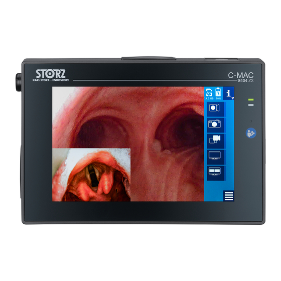
Application NOTICE Data transmission fault If the SD card or connecting cable is removed during image/video capture, this can result in data loss. Ensure that the SD card and connecting cable are connected to the device during capture. 6.3.2 Inserting the USB stick ü... - Page 27 Application Start screen with video unit connected Information bar Access to information area Image and video area Video unit functions Menu bar Access to function space Status bar Information bar The information bar displays the active functions of the video unit (e.g., video recording and image position) and also notifies you when the battery needs charging, see chapter Icons and functions on the user interface [p. 30].
-
Page 28: Information Area
Application – Function space This contains the settings for the monitor and the accessories that are being used, see chapter Function space [p. 28]. 6.4.2 Information area The information area provides the following details: – Item number, firmware version, and, depending on the connected accessories, the number of cycles and the operating time of the connected video unit –... -
Page 29: Password-Protected Settings
Application Functions Saved captures Scroll bar Depending on which accessories are connected and which functions are enabled, certain functions are not available and are therefore not displayed, see chapter Icons and functions on the user interface [p. 30] and see chapter Password-protected settings [p. 29]. 6.4.4 Password-protected settings A default password is set when the product is delivered, see chapter Access and security concept [p. 43]. -
Page 30: Icons And Functions On The User Interface
Application Depending on which accessories are connected and which functions are enabled, certain functions are not available and are therefore not displayed, see chapter Icons and functions on the user interface [p. 30]. 6.4.5 Icons and functions on the user interface Functions on the start screen Icon Meaning... - Page 31 Application Icon Meaning This function is only available if an SD card has been inserted. Image capture with freeze Freezes the live image, see chapter Capturing stills and recording videos [p. 39]. This button is only available if an SD card has been inserted and the Freeze function has been enabled.
- Page 32 Application Functions in the function space Icon Description Microphone Switches on or mutes the microphone. Default setting: The microphone is muted and must be activated manually. Screen settings The Screen settings menu displays and adjusts the hue, saturation, contrast, and brightness settings of the monitor, see chapter Screen settings [p. 37]. Brightness Adjusts the brightness of the monitor.
- Page 33 Application Icon Description SD card to USB stick Transfers the content of the SD card to a USB stick, see chapter Copying data from an SD card to a USB stick [p. 42]. Only available if an SD card and USB stick have been inserted. Clear SD card Deletes the content of the SD card.
- Page 34 Application Functions in the password-protected area Icon Description Sound recordings Enables or disables the microphone for sound recordings. Automatic video recording Enables or disables automatic video recording. If the function is enabled, video recording starts automatically as soon as a video unit is connected. Change password Changes the password for the protected area, .
-
Page 35: Images And Videos
Application Icon Meaning Image position The live image has been rotated by 180°. No memory card No memory card has been recognized. Memory card present The inserted memory card has been recognized. Low memory capacity Less than 300 MB of memory capacity is available. Critical memory capacity Flashing red: Less than 100 MB of memory capacity is available. - Page 36 Application Before each use, check whether the correct image position has been selected. 6.5.1.1 Full screen display If only one video unit is connected, the live image fills the entire screen. If two video units are connected, the live image of the primary video unit is shown in full screen. To change the primary video unit, tap the Switch video unit button.
-
Page 37: Screen Settings
Application To change the primary video unit, tap the Switch video unit button. To switch the view, tap the Picture-in-picture or Full screen button. 6.5.1.4 Changing the image position The displayed live image can be rotated by 180° and saved. Tap the Image position button in the function space. - Page 38 Application Recommended settings for accessories Item Brightness Contrast Saturation Hue [%] 8402X 8401AX, 8401AXC, 8401BX, 8401BXC, 8401DXC, 8401GXC, 8401HX, 8401HXP, 8401KXC 8402XS 8403AX, 8403AXC, 8403BX, 8403BXC, 8403HX 8403DXC, 8403EXC, 8403GXC, 8403HXP, 8403KXC, 8403MXC 8404AX, 8404AXC, 8404BX, 8404BXC, 8404HX 8404DXC, 8404EXC, 8404GXC, 8404KXC, 8404MXC, 8404HXP 8403XS, 8403XSI 8403XSP...
-
Page 39: Capturing Stills And Recording Videos
Application 6.5.3 Capturing stills and recording videos Stills and video sequences of the current procedure can be captured and saved to an SD card. 6.5.3.1 Recording videos ü A video unit has been connected. ü An SD card with sufficient memory capacity has been inserted. Tap the Video recording button to start the recording. -
Page 40: Viewing And Deleting Captures
Application Tap the Freeze button. ð The image is frozen. ð The Freeze icon appears on the information bar. To return to the live image display, tap the Freeze button again. 6.5.4 Viewing and deleting captures Captures can be viewed and deleted in the image and video area of the function space. The most recently created stills and videos are displayed in a preview. -
Page 41: Performing White Balance
Application 6.5.4.1 Viewing a capture To view the saved images, tap the last saved image. ð The area containing the saved images is displayed: Tap a capture. ð The capture is displayed. 6.5.4.2 Deleting a capture Tap a capture to mark it for deletion. Hold down the Delete button until the button has been completely filled in: ð... -
Page 42: Activating The Timer
Application Hold the connected video unit in front of a white, non-reflective object (e.g., white gauze). Hold down the White balance button in the function space until the icon is filled in and flashes briefly. ð After approx. 2 s, the icon will flash briefly. The white balance is complete. 6.5.6 Activating the timer The timer measures the time required for an application, precisely to the second. -
Page 43: Setting The Date And Time
The default password when the product is delivered is: 0000 . KARL STORZ recommends that you change the password and store it in a safe place. If you lose the password, you will have to contact KARL STORZ Service. - Page 44 Application To change the password, go to the Password-protected settings area and call up the Change password menu. ð The following dialog appears: Enter a numerical password of between 4 and 8 digits in the top input field. Enter the new password again in the bottom input field. Tap the checkmark to confirm the entry.
-
Page 45: Maintenance, Servicing, Repairs, And Disposal
The battery’s capacity decreases over time. KARL STORZ recommends replacing the battery after 2 years. The battery may only be replaced by persons authorized by KARL STORZ. 7.3 Maintenance Maintenance work may only be carried out by KARL STORZ or a company authorized by KARL STORZ. Interval Maintenance work... -
Page 46: Visual Inspection
Measure the patient leakage current. 7.5 Repairing the product Repair work may only be performed by KARL STORZ or by a company authorized by KARL STORZ. The interventions described in this instruction manual are exempt from this rule. Please contact your local KARL STORZ subsidiary or authorized dealer (see the list of subsidiaries). -
Page 47: Accessories And Spare Parts
C-MAC TROLL-E Mobile Stand 20020086 8.2 Spare parts Item Order no. Power supply unit, for C-MAC® Monitor 8404ZX ET27-30-0006091 VESA 75 Quick Clip, with 4 clamping screws, for mounting C- 8401YCA MAC to holding arms up to diameter 25 mm Exchangeable adaptors for charger Item Order no. -
Page 48: Electromagnetic Compatibility
Electromagnetic compatibility 9 Electromagnetic compatibility 9.1 General notes on the operating environment The product is suitable for use in professional healthcare settings. Professional healthcare facilities include physician offices, dental offices, limited care facilities, freestanding surgical centers, freestanding birth centers, multiple treatment facilities, hospitals (emergency rooms, patient rooms, intensive care, surgical rooms, outside the HF-shielded room of an ME system for MRT). - Page 49 Electromagnetic compatibility Interference im- EN/IEC 60601 test Compliance level Electromagnetic envi- munity tests level ronment – guidelines Voltage interruption: Voltage interruption: ated with an uninter- ruptible power supply 100% for 250/300 cy- 100% for 250/300 cy- or a battery. cles cles Magnetic field at 30 A/m at 50 Hz / 30 A/m at 50 Hz / If image distortion oc-...
- Page 50 Electromagnetic compatibility Test fre- Frequency Radio service Modulation Immunity Compliance quency band test level level 1720 1700 – 1990 GSM 1800, Pulse modula- CDMA 1900, tion 1845 GSM 1900, 217 Hz DECT, 1970 LTE band 1, 3, 4, 25, UMTS 2450 2400 –...
- Page 51 Electromagnetic compatibility Interference immunity EN/IEC 60601 test Compliance Electromagnetic envi- tests level level ronment – guidelines Field strengths from fixed HF transmitters as deter- mined by an electromag- netic site survey should be less than the compli- ance level in each fre- quency range d = 1.2 √P 80 MHz to 800 MHz...
- Page 52 Electromagnetic compatibility Interference emission measure- Compliance Electromagnetic environment – ments guidelines Voltage fluctuations/flicker emis- public low voltage power supply sions acc. to IEC 61000-3-3 network that supplies buildings used for domestic purposes. 9.6 Table 5 – Recommended separation distances between portable and mobile HF communications equipment and the product The product is intended for use in an electromagnetic environment in which HF disturbances are controlled.
-
Page 53: Errors And Messages
– Video unit electronics will go. defective – Send the product to – Screen defective KARL STORZ for repair. The touch screen does not – Screen defective – Restart the system. react. – System error –... - Page 54 Reconnect the power supply unit. – If the status LED continues flashing, send the product to KARL STORZ for repair. The battery charge state LED – The monitor is new. It – Once the monitor has lights up green, but the dis- has not yet been been charged 5 times at...
-
Page 55: Subsidiaries
E-mail: pisarna@karlstorz.si Phone: +54 11 4718 0919, Fax: +54 11 4718 2773 E-mail: info@karlstorz.com.ar KARL STORZ Polska Sp. z o.o. ul. Bojkowska 47, 44-100 Gliwice, Poland KARL STORZ Endoskopi Norge AS Phone: +48 32 706 13 00, Fax: +48 32 706 13 07 Stamveien1, 1483 Hagan, Norway E-mail: info-pl@karlstorz.com... - Page 56 E-mail: info-az@karlstorz.com No. 8 Commonwealth Lane #03-02, Singapore 149555, Singapore Phone: +65 69229150, Fax: +65 69229155 KARL STORZ ENDOSKOPE – East Mediterranean and Gulf (Offshore) S.A.L. E-mail: infoasia@karlstorz.com Spark Tower 1st floor Charles Helou St., Horch Tabet – Sin El Fil, Beirut,...
- Page 57 Subsidiaries Instructions for use • C-MAC Monitor • CFH518_EN_V1.0_12-2021_IFU_CE-MDR...
- Page 58 Subsidiaries Instructions for use • C-MAC Monitor • CFH518_EN_V1.0_12-2021_IFU_CE-MDR...
- Page 59 Subsidiaries Instructions for use • C-MAC Monitor • CFH518_EN_V1.0_12-2021_IFU_CE-MDR...
- Page 60 KARL STORZ SE & Co. KG Dr.-Karl-Storz-Straße 34 78532 Tuttlingen Postfach 230 78503 Tuttlingen Germany Phone: +49 7461 708-0 Fax: +49 7461 708-105 E-mail: info@karlstorz.com www.karlstorz.com...
Need help?
Do you have a question about the 8404ZX and is the answer not in the manual?
Questions and answers