Advertisement
Quick Links
.........
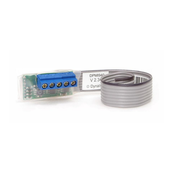
DPMI940
DyNet Auxiliary Input Interface
Installation Manual
features
4 x Dry Contact Inputs – Presented on a 2mm pitch 160mm
long ribbon cable.
1 x RS485 DyNet Port - Available on a 5 way terminal block
with maximum conductor size of 2mm.
Powered from the DyNet Network – No need for an
external power supply.
Simple Installation - Compact enclosure allows the device to
be conveniently placed near the device to be controlled. All
connections are accessible without disassembly
Motion Detector Mode - Allows easy connection of third
party motion detectors to the DyNet RS485 network.
mounting details
40 mm
side view
top view
important notes
Read Instructions – We recommend that you read this
Instruction Manual prior to commencement of installation.
Special Programming – This device will only operate in basic
modes unless programmed via a computer. If programming is
required, contact your local agent for details. The factory default
settings are Area 1 Presets 1, 2, 3 and 4.
Installation Location – Install in a dry location, close to the
equipment to be interfaced with.
Cable Length – Cable to the ribbon cable flying leads should not
exceed 1000mm long.
RS485 Data Cable – Use screened, stranded RS485 data cable
with three twisted pairs. Segregate from mains cables by 300mm
minimum. Connect devices in a 'daisy chain'. A data cable that is
connected to an energised device is live. Do not cut or terminate
live data cables.
Ribbon Cable
electrical diagram
Advertisement

Related Manuals for Philips dynalite DPMI940


Summary of Contents for Philips dynalite DPMI940
- Page 1 ……… DPMI940 DyNet Auxiliary Input Interface Installation Manual features important notes Read Instructions – We recommend that you read this 4 x Dry Contact Inputs – Presented on a 2mm pitch 160mm Instruction Manual prior to commencement of installation. long ribbon cable.
- Page 2 DPMI940 Instruction Manual Revd.Doc Specifications subject to change without notice Dynalite manufactured by WMGD Pty Ltd (ABN 33 097 246 921) Unit 6, 691 Gardeners Road Mascot NSW 2020 Australia Tel: +61 2 8338 9899 Fax: +61 2 8338 9333 E-Mail: dynalite.info@philips.com Web: Philips.com/dynalite...