
Related Manuals for Mitsubishi Electric LGH-50RSDC-E1


Summary of Contents for Mitsubishi Electric LGH-50RSDC-E1
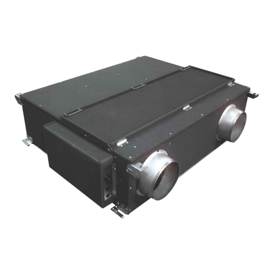
- Page 1 July 2019 No. U177-B LOSSNAY HANDBOOK MODEL LGH-50RSDC-E1 Nameplate Warning: Repair work must be performed by the manufacturer, its service agent or a similarly qualified person in order to avoid hazards.
-
Page 2: Table Of Contents
Contents 1. Safety precautions ............... 3 2. Names of components ..............4 3. Specifi cations ................5 4. Outside dimensions ..............6 5. Electrical wiring diagram ............. 7 6. Basic circuit diagrams ............... 8-9 7. Fundamentals of operation ........... 10-15 8. -
Page 3: Safety Precautions
1. Safety precautions Be sure to read the following precautions thoroughly before the maintenance, and then inspect and repair the product in a safe manner. The types and levels of danger that may arise if the product is handled incorrectly are described with the warning symbols shown below. -
Page 4: Names Of Components
2. Names of components Control box Lossnay core Damper plate Air exhaust fan (EA fan) Maintenance cover Air supply fan (SA fan) Air filter (4 filters) ─ 4 ─... -
Page 5: Specifi Cations
3. Specifi cations Model LGH-50RSDC-E1 Heat exchange system Air-to-air Total heat exchange (sensible heat + latent heat exchange) Heat exchange element material Partition spacing plate-special treated paper Cladding Galvanized steel sheet Heat insulating material Self-extinguishing urethane foam Motor DC brushless motor. Two units Blower 220 mm diameter. -
Page 6: Outside Dimensions
4. Outside dimensions Unit (mm) ─ 6 ─... -
Page 7: Electrical Wiring Diagram
5. Electrical wiring diagram T h i s p r o d u c t m u s t b e c o n n e c t e d t o a l l p o l e m a i n s w i t c h w i t h a t l e a s t 3 m m d i s c o n n e c t i o n . ─... -
Page 8: Basic Circuit Diagrams
6. Basic circuit diagrams Circuit board diagrams and check points (1) Large printed circuit board (PCB) (Left) EA fan motor SA fan motor LED 3 (green) LED 2 (red) During EA fan operation: lit sensor signal sensor signal During SA fan operation: lit (CN9) (CN8) During an error: blinking... - Page 9 (2) Small PCB (right) Transformer output LED 1 (red) LED 11 (green) 11 V to 20 V AC 12 V DC 5 V DC Normal: lit During trial operation: lit (CN14) (IC6) (C20) (C20) During an error: blinking During an error: blinking During an error: 0 Ω...
-
Page 10: Fundamentals Of Operation
7. Fundamentals of operation Description of the PCB (1) Air volume control Air volume Fan speed selection (Reference value under rated static pressure) Operation (TM2, TM3) (l/s) All contacts : OFF Stop Speed 1 (Contact between 1 and COM) : ON Speed 2 (Contact between 2 and COM) : ON Speed 3 (Contact between 3 and COM) : ON Running... - Page 11 Cold region operation mode When using the unit in cold region, set the air supply (SA) fan in the SA intermittent operation mode to pre- vent the Lossnay core from freezing. The fan operation is based on the measured outside air (OA) tempera- ture as below.
- Page 12 Automatic ventilation algorithm temperature chart < Pattern 1> Chart 1. Automatic ventilation algorithm temperature chart during the switch SW 1-6 OFF setting. When an outdoor temperature has not reached 17ºC When an outdoor temperature has reached 17ºC or higher within 24 hours within 24 hours Bypass Bypass...
- Page 13 (3) Operation monitor output When the function setting switch SW 1-2 (for operation monitor output with delay function) is set to OFF, and the switch SW 1-5 (for operation monitor output) is set to ON, the operation monitor signal can be output from the monitor terminal block (TM4) on the circuit board.
- Page 14 (6) Trial operation function This is a function for operating the Lossnay without external signals (contact signals). With this function, con- necting condition of the AC power supply line and the wirings can be confi rmed. Also, the Lossnay can be forced to operate in case of system down.
- Page 15 (8) Function setting switches 7 Automatic air volume increasing during bypass setting Trial operation OFF ON Operation Operation monitor output with delay function Not increasing. Setting for exhaust fan in cold region operation mode When unit is in bypass operation except power bypass mode, the unit fan speed is automatically Ventilation priority mode during ventilation setting input on increased 1 step.
-
Page 16: Troubleshooting
8. Troubleshooting Work precautions • When removing or touching a transformer, printed circuit board or other parts, make sure to turn off the power supply isolator. Even after disconnecting the power supply isolator, the voltage is still high in the ca- pacitors on the printed circuit boards. - Page 17 (2) Troubleshooting and repair method When any LEDs on the circuit boards are blinking The type of failure is shown by the number of blinking times of LED 1 (red), LED 11 (green), LED 2 (red) and LED 3 (green) on the circuit boards. The LED blink interval is 0.25 seconds for both lit and unlit. The display duration is approximately 5 seconds.
- Page 18 LED 1 LED 11 LED 2 LED 3 Symptom Cause Corrective action (red) (green) (red) (green) EA fan opera- The EA fan does not Check whether the fan turns by hand. tion failure rotate properly. EA fan motor wire Check the wiring of the connector (CN7) on connection error the circuit board and the fan motor.
- Page 19 LED 1 LED 11 LED 2 LED 3 Symptom Cause Corrective action (red) (green) (red) (green) OA thermistor Connector connection Check the wiring of the connector (CN16) on failure error of thermistor the circuit board and the thermistor. blinks Thermistor malfunc- Check the resistance of the thermistor.
- Page 20 When the unit does not operate or operates irregularly Symptom Cause Corrective action The fans do not Power is not supplied to the unit. Check the power supply. operate. (220 to 240 V AC 50 Hz) Power supply voltage is out of rated Check the power supply.
- Page 21 Symptom Cause Corrective action After opera- The function setting switch SW 1-2 When the switch SW 1-2 is ON, the fan tion has been (Operation monitor output with delay continues to operate for 3 minutes after stopped, the fan function) is ON. Lossnay operation has been stopped.
- Page 22 Temperature and thermistor resistance table Temperature Resistance value (kΩ) Temperature Resistance value (kΩ) (°C) (TYP) (°C) (TYP) ∞ 53.9 - 32.8 31.3 29.8 28.4 27.1 25.9 24.7 23.5 22.5 21.5 20.6 19.6 18.8 18.0 17.2 16.4 15.7 15.1 14.4 13.9 13.3 12.8 12.2...
-
Page 23: Overhauling Procedures
9. Overhauling procedures Work precautions • When touching the electric components such as circuit boards and fan motors, do not touch the components for more than 5 minutes after power-off, and then start servicing. • Before replacing parts, repair troubled sections according to the instructions described in the troubleshoot- ing. - Page 24 Remove the casing (upper). EA fan SA fan These parts are drawn translucently to show inner parts. Air Exhaust (EA) fan Unscrew the screws (two PTT screws 4 x 8, indicated by ) for the connector cover next to the EA fan. EA fan Disconnect all the connectors for the fans.
- Page 25 Air Supply (SA) fan Unscrew the screws (six PTT screws 5 x 10, indicated (3) Circuit board parts Unscrew the screws (four screws, indicated by ) for the control cover. When replacing the lead wires or damper parts, unscrew the fi xing screws (two PTT screws 4 x 8, indicated ) for the fi...
- Page 26 (4) Lossnay core Unscrew the screws (two screws, indicated by ) for the core holder. Core holder Draw the Lossnay cores from the unit by holding the Lossnay core Handles handles. (5) Damper parts and Damper motor Remove the fi x plate for the lead wires and disconnect the wires from the circuit board. (Refer to (3) (page 25)). Unscrew the screws (two screws, indicated by ) for the damper, and draw the damper from the unit.
- Page 27 Unscrew the screws (three screws, indicated by ) for GM cover the GM cover. Remove the GM cover. Unscrew the screws (two screws, indicated by ) for the damper motor. Damper motor (GM) When reassembling Reassemble the unit in the reverse order of disassembly. After reassembly, always make a test run to be sure that the unit operates properly.
-
Page 28: Parts Catalog
10. Parts catalog Please note the following when using the parts catalog. 1. When ordering parts, always indicate the part number, part name, and the number of parts required. 2. It may take time for you to receive the parts. Make an inquiry about a rush order. 3. - Page 29 LGH-50RSDC-E1 * * * * * 24pcs. * shows accessory parts. ─ 29 ─ LGH-50RSDC-E1...
- Page 30 LGH-50RSDC-E1 Critical Q'ty Name of part Parts No. Remarks pcs/unit safety PTT screw 4×8 H00 000 487 Flange R50 028 610 Cord band Y55 001 223 PT screw 6×12 H00 000 244 Hanger R50 095 380 Wiring diagram Y50 150 368...
- Page 31 ─ 31 ─ LGH-50RSDC-E1...
- Page 32 LGH-50RSDC-E1 Critical Q'ty Name of part Parts No. Remarks pcs/unit safety 31 Motor fix plate R50 488 713 32 Motor Y50 123 453 33 Flinger Y50 031 608 34 U ring K81 417 102 35 Cord bush M45 649 226...
- Page 33 ─ 33 ─ LGH-50RSDC-E1...
- Page 34 LGH-50RSDC-E1 Critical Q'ty Name of part Parts No. Remarks pcs/unit safety 61 Damper plate Y50 123 732 62 Fix plate Y50 123 727 63 Pull spring Y50 123 156 64 Bush D40 072 225 65 Damper Y50 123 729 66 Damper support...