Table of Contents
Advertisement
Advertisement
Table of Contents

Related Manuals for QSC Q-SYS QIO-ML4i


Summary of Contents for QSC Q-SYS QIO-ML4i
- Page 1 ® ™ Hardware User Manual Q-SYS™ QIO Endpoints QIO-ML4i Network Audio I/O Expander for Q-SYS QIO-L4o Network Audio I/O Expander for Q-SYS QIO-ML2x2 Network Audio I/O Expander for Q-SYS QIO-GP8x8 Network Control I/O Expander for Q-SYS TD-001667-01-A *TD-001667-01*...
- Page 2 EXPLANATION OF TERMS AND SYMBOLS The term “WARNING” indicates instructions regarding personal safety. Failure to follow them may result in bodily injury or death. The term “CAUTION” indicates instructions regarding possible damage to physical equipment. Failure to follow them may result in equipment damage to equipment that may not be covered under the warranty.
-
Page 3: Maintenance And Repair
QSC authorized service station or an authorized QSC International Distributor. QSC is not responsible for any injury, harm or related damages arising from any failure of the customer, owner or user of the apparatus to facilitate those repairs. -
Page 4: What's In The Box
What’s in the Box QIO-ML4i (1x) (4x) (2x) QIO-ML4i Mic/Line In connector Power connector (orange) (black) (2x) (4x) (4x) Surface mounting Foam spacer M4 x 6 mm pan head bracket screws (1x) (1x) Warranty Safety and statement regulatory statements QIO-L4o (1x) (4x) (2x) - Page 5 QIO-ML2x2 (1x) (2x) (2x) QIO-ML2x2 Mic/Line In connector Line Out connector (orange) (green) (2x) (2x) (4x) Power connector Surface mounting Foam spacer (black) bracket (4x) (1x) (1x) M4 x 6 mm pan head Warranty Safety and screws statement regulatory statements QIO-GP8x8 (1x) (2x)
-
Page 6: Power Requirements
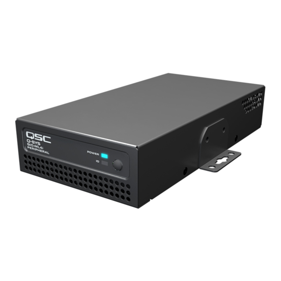
Introduction The Q-SYS QIO Endpoints Series offers multiple products that can serve numerous audio and control purposes. ML4i The Q-SYS ML4i is a network audio endpoint native to the Q-SYS Ecosystem, serving as a mic/line input that enables network-based audio distribution. - Page 7 Connections and Callouts ML4i Front Panel 1. Power LED – illuminates blue when the Q-SYS ML4i is powered on 2. ID LED – LED blinks green when placed into ID Mode via ID Button or Q-SYS Configurator 3. ID Button – Locates the ML4i in Q-SYS Designer Software and Q-SYS Configurator ML4i Rear Panel 1.
- Page 8 L4o Front Panel 1. Power LED – illuminates blue when the Q-SYS L4o is powered on 2. ID LED – LED blinks green when placed into ID Mode via ID Button or Q-SYS Configurator 3. ID Button – Locates the L4o in Q-SYS Designer Software and Q-SYS Configurator L4o Rear Panel 1.
- Page 9 ML2x2 Front Panel 1. Power LED – illuminates blue when the Q-SYS ML2x2 is powered on 2. ID LED – LED blinks green when placed into ID Mode via ID Button or Q-SYS Configurator 3. ID Button – Locates the ML2x2 in Q-SYS Designer Software and Q-SYS Configurator ML2x2 Rear Panel 1.
- Page 10 GP8x8 Front Panel 1. Power LED – illuminates blue when the Q-SYS GP8x8 is powered on 2. ID LED – LED blinks green when placed into ID Mode via ID Button or Q-SYS Configurator 3. ID Button – Locates the GP8x8 in Q-SYS Designer Software and Q-SYS Configurator GP8x8 Rear Panel 1.
-
Page 11: Rack Mount Installation
Rack Mount Installation Q-SYS QIO Endpoints are designed to be mounted in a standard rack-mount unit using the Q-SYS 1RU rack tray (FG-901528-00). The rack tray accommodates up to four QIO Endpoint units of either product length. Rack Tray Hardware (1x) (3x) (14x) -
Page 12: Surface Mount Installation
NOTE: Fasteners for attaching the bracket to a surface are pictured as an example but not provided. Freestanding Installation For freestanding installation on a table top, apply the four adhesive foam spacers to the underside of the unit. Specifications and Dimensions Product specifications and dimension drawings for the QIO Endpoints can be found online at www.qsc.com. -
Page 13: Warranty
For a copy of the QSC Limited Warranty, visit the QSC, LLC., website at www.qsc.com. © 2022 QSC, LLC. All rights reserved. QSC and the QSC logo, Q-SYS, and the Q-SYS logo are registered trademarks of QSC, LLC in the U.S. Patent and Trademark Office and other countries.
Need help?
Do you have a question about the Q-SYS QIO-ML4i and is the answer not in the manual?
Questions and answers