
Related Manuals for Lidix CL-2

Summary of Contents for Lidix CL-2
- Page 1 CL-2 Service Manual Service Manual For CL-2 Date. Rev. Notice. 2018.05 2018.12...
- Page 2 1. Please read this service manual, before test and setting change of CL-2. 2. Follow this manual to prevent any physical/material damage and operating safely and solve the problem. 3. Reproduction, copying, or fabrication of any information contained in this manual, without prior consent of LIDIX, is forbidden.
-
Page 3: Table Of Contents
CL-2 Service Manual < Contents > 1. SAFETY 1-1. Safety Information 1-2. Operational Environment 1-3. Installation/Moving 1-4. Maintenance/Checking 2. APPEARANCE 2-1. Machine Overview 2-2. Operation Panel Overview 2-3. Basic Operation 3. Counting mode 3-1. Value Mode 3-2. Fitness Mode 3-3. TITO Mode 3-4. - Page 4 CL-2 Service Manual < Contents > 4. User Setting 4-1. Function 4-2. Ex Device 4-3. UI Config 4-4. Pocket Size 4-5. Product Info 5. ENG Setting (Engineer setting) 5-0. Entering ENG setting 5-1. Count Adjustment 5-2. Motor Calibration 5-3. CIS Calibration 5-4.
- Page 5 CL-2 Service Manual < Contents > 6. Error Code 6-1. < ROI > error 6-2. < Value > Error 6-3. < IR > Error 6-4. < UV > Error 6-5. < MG > Error 6-6. < US > Error 6-7. < Unfit > Error 6-8.
- Page 6 CL-2 Service Manual < Contents > 8. Daily cleaning 9. Accessories & Specification...
-
Page 7: Safety Information
CL-2 Service Manual 1-1. Safety Information These warnings and precautions are included in order to prevent injury to you and others, as well as preventing any potential damage to your machine. Be sure to read and understand all of these instructions before using the machine. -
Page 8: Operational Environment
CL-2 Service Manual 1-2. Operational Environment Warning Do not use if the power cord is damaged or if the electrical outlet is not grounded. ► This could result in electric shock or fire. Do not place anything on top of the machine (water, small metal or heavy objects, etc.). - Page 9 CL-2 Service Manual 1-2. Operational Environment Caution Be careful not to put your hand, hairs and clothes(including tie) when handling machine. Do not forcefully pull the note out during counting. ► It can cause damage to the machine. Be care when removing jammed notes.
-
Page 10: Installation/Moving
CL-2 Service Manual 1-3. Installation/Moving Caution Before moving the machine, turn the power off and disconnect the cord. Make sure lift the machine using both hands. ►The machine could fall, causing injury or machine damage. Do not place the machine on an unstable surface. -
Page 11: Maintenance/Checking
CL-2 Service Manual 1-4. Maintenance/Checking Caution Unplug this product from the wall outlet before cleaning the inside of the machine. Do not clean the machine with benzene, paint thinner or alcohol; do not spray water directly into the machine. ►This could result in electric shock or fire. -
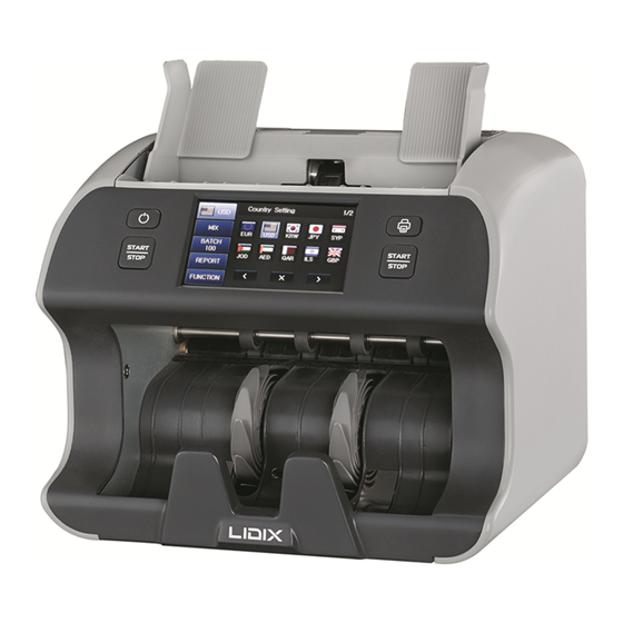
Page 12: Machine Overview
CL-2 Service Manual 2-1. Machine Overview 1 Front Case 8 Rear Cover 2 Front Cover 9 Thickness Dial 3 Stacker 10 Interface Connector 4 Hopper guide 11 Inlet 5 Start/Stop Button (LEFT) + Power Button 12 Side Case R 6 Start/Stop + Print Button (RIGHT) -
Page 13: Operation Panel Overview
CL-2 Service Manual 2-2. Operation Panel Overview Configuration FUNCTION FUNCTION Power button. Print Button. Left Start / Stop Key to manual working. Right Start / Stop Key to manual working. - Page 14 CL-2 Service Manual 2-2. Operation Panel Overview Screen Configuration ADD function S/N function. (Available for specific currency.) White letter -> Enabled / Red letter -> Disabled Selecting Counting speed for each function. Currency select button. Count mode select button. (Count / MIX / SP) Batch setting button.
-
Page 15: Basic Operation
CL-2 Service Manual 2-3. Basic Operation STEP 1. Plug the power cord into the power receptacle. STEP 2. Turn on CL-2 by pressing Power Switch. STEP 3. Select the Currency STEP 4. Select a Counting Mode. STEP 5. Adjust Hopper guide to the notes to be counted. -
Page 16: Counting Mode
CL-2 Service Manual 3. Counting mode 3-1. Currency Setting Mode Description You can choose Currency when you Currency click this button. - Page 17 CL-2 Service Manual 3. Counting mode 3-2. Count Mode Setting Mode Description COUNT Count only Pcs. It count the all denomination of MIX MODE selected currency. Recognize of first note automatically and count the same value denomination. TITO count function...
- Page 18 CL-2 Service Manual 3. Counting mode 3-3. Batch Setting Mode Description If you select the Batch function on the screen, the Batch mode setting screen will be Shown. Batch Setting As you select the amount the denominations will be assigned in the pocket.
-
Page 19: Report
CL-2 Service Manual 3. Counting mode 3-4. Report If you select the Report function on the screen, the Report screen will be shown on the screen. Mode Description You can see the detail information of last counted result. You can see the detail information of added counted result. - Page 20 CL-2 Service Manual 4. Function Mode (User setting) 4. Function Mode. 4. Function Mode (User setting) Function mode is for the user setting. You can set every category each subject. Please refer the following manual.
- Page 21 CL-2 Service Manual 4. Function Mode (User setting) 4. Function Mode. 4-1. Information Mode Description You can see the version of CL-2 Information and Boot...
- Page 22 CL-2 Service Manual 4. Function Mode (User setting) 4. Function Mode. 4-2. Count Detail Mode Description You can make it Enable or Disable when you click the Count Detail button then You can set count detail for some modes (Count / Mix / SP)
- Page 23 CL-2 Service Manual 4. Function Mode (User setting) 4. Function Mode. 4-3. Interface Mode Description You can connect CL-2 with PC by activate “PC” PC PORT You can connect CL-2 Printer with Printer by activate “Printer” You can connect CL-2 with Customer Display by activate “CD”...
- Page 24 CL-2 Service Manual 4. Function Mode (User setting) 4. Function Mode. 4-4. CF Setting (Value) Mode Description Checking CF notes with UV Sensor Checking CF notes with MG Sensor Checking CF notes with IR Top IR T Sensor *When you click red circled button, you can change “Value”...
- Page 25 CL-2 Service Manual 4. Function Mode (User setting) 4. Function Mode. 4-4. CF Setting (Count) Mode Description Checking Short size. You can set mm size detection Checking Length size. You can set mm size detection You can set UV detection level.
- Page 26 CL-2 Service Manual 4. Function Mode (User setting) 4. Function Mode. 4-5. Language Mode Description You can set CL-2’s operating English language to English. Other language will be developed following the requests.
- Page 27 CL-2 Service Manual 4. Function Mode (User setting) 4. Function Mode. 4-6. Speed Setting Mode Description You can set counting speed 800 or 1000 1000 or 1200 notes / min. 1200...
- Page 28 CL-2 Service Manual 4. Function Mode (User setting) 4. Function Mode. 4-7. Date & Time Setting Mode Description Date You can set time to fit your local &Time time by this setting. Setting...
- Page 29 CL-2 Service Manual 4. Function Mode (User setting) 4. Function Mode. 4-8. Printer Mode Description You can set how many copies will Copies you print at once. You can set which S/N option will SN Option you print. Image and OCR.
- Page 30 CL-2 Service Manual 4. Function Mode (User setting) 4. Function Mode. 4-9. Buzzer Mode Description You can Enable/ Disable the Buzzer buzzer sound when you click the button.
- Page 31 CL-2 Service Manual 4. Function Mode (User setting) 4. Function Mode. 4-10. Power Save Time Mode Description You can set screen saver function. When you use this function, you can use screen saver by setting Power time. Save Time You can set time 1s ~ 60s to turn on the screen saver.
- Page 32 CL-2 Service Manual 4. Function Mode (User setting) 4. Function Mode. 4-11. Main Font Color Mode Description You can choose Main font color Main Font which you want when you click this Color button.
- Page 33 4. Function Mode (User setting) 4. Function Mode. 4-12. LAN Mode Description You can connect CL-2 with PC by LAN communication. This function will be explained with additional manual. *This function is not developed yet. *This function is for specific...
- Page 34 CL-2 Service Manual 4. Function Mode (User setting) 4. Function Mode. 4-13. Batch Keep Off Mode Description Keep batch off Ex) 10 sec. Count the note as Batch batch off but if 10 sec. is over Keep Off without counting, the batch is...
- Page 35 CL-2 Service Manual 5. ENG Setting (Engineer setting) 5-0. Entering ENG setting. Press “1, 2, 3, 4” to enter ENG setting mode. Please be informed that the calibration result of motors and sensors are different depend on each machine. Result value is reference for our engineers.
- Page 36 CL-2 Service Manual 5. ENG Setting (Engineer setting) 5-1. Product Information. You can see the manufactured date of the machine and installed SW version.
- Page 37 CL-2 Service Manual 5. ENG Setting (Engineer setting) 5-2. CF Setting. Please choose the currency which you want to set CF setting. You can see the manufactured date of the machine and installed SW version.
- Page 38 CL-2 Service Manual 5. ENG Setting (Engineer setting) 5-2. CF Setting. Category Explanation Denom Value of Denomination. Please choose denom which you want to set CF setting. Version Issued version setting. This depends on currency and denom. You can change CF setting with issued version.
- Page 39 CL-2 Service Manual 5. ENG Setting (Engineer setting) 5-3. Function Setting. You can set functions with each category. Following pages will inform you the below list in detail. Active Mode 5. Rear Cover Open Error Printer Settings 6. Display CF Uart Settings 7.
- Page 40 CL-2 Service Manual 5. ENG Setting (Engineer setting) 5-3-1. Active Mode. You can change the setting of Active Mode. You can enable/ disable the function in your own. Category Explanation Category Explanation Count Enable/ Disable Count Mode. Issue Enable/ Disable Issue Mode.
- Page 41 CL-2 Service Manual 5. ENG Setting (Engineer setting) 5-3-2. Printer Settings. You can set Printer connection setting for your printer. You can set Baudrate, Printer type, Paper size, Line feed. 5-3-3. Uart Settings. You can choose which customer display you will use.
- Page 42 CL-2 Service Manual 5. ENG Setting (Engineer setting) 5-3-4. Stacker Full. You can set Stacker Batch Size hear. If you choose “OFF” the limit of Stacker Size will be set as unlimited.
- Page 43 CL-2 Service Manual 5. ENG Setting (Engineer setting) 5-3-5. Rear Cover Open Error. You can Enable or Disable the rear cover open error when you click the button.
- Page 44 CL-2 Service Manual 5. ENG Setting (Engineer setting) 5-3-6. Display CF. You can Enable or Disable the display CF when you click the button.
- Page 45 CL-2 Service Manual 5. ENG Setting (Engineer setting) 5-3-7. Direction. You can set the direction when you click the button.
- Page 46 CL-2 Service Manual 5. ENG Setting (Engineer setting) 5-3-8. Record Save. You can Enable or Disable the record save when you click the button.
- Page 47 CL-2 Service Manual 5. ENG Setting (Engineer setting) 5-4. Adjustment. You can calibrate the Motors and Sensors in this page. Please be informed that calibration need to be done after cleaning or upgrade with latest SW. In other case, we will request you 5-4-1.
- Page 48 CL-2 Service Manual 5. ENG Setting (Engineer setting) 5-4-2. CIS Sensor. Please put the CIS Calibration sheet as left picture. Close the rear cover. Then, press “O” to calibrate the CIS sensor.
- Page 49 CL-2 Service Manual 5. ENG Setting (Engineer setting) 5-4-3. UV Sensor. Press “O” to calibrate UV sensor. 5-4-4. US Sensor. Press “O” to calibrate US sensor.
- Page 50 CL-2 Service Manual 5. ENG Setting (Engineer setting) 5-4-5. MG Sensor. Please be informed that MG sensor is most sensitive sensor in the machine. So calibration of MG sensor is available in Factory only.
- Page 51 CL-2 Service Manual 5. ENG Setting (Engineer setting) 5-4-6. Hopper Sensor. Press “O” to calibrate Hopper sensor. 5-4-7. Stacker Sensor. Press “O” to calibrate Stacker sensor.
- Page 52 CL-2 Service Manual 5. ENG Setting (Engineer setting) 5-4-8. Motors. You can calibrate Motors with each category. 5-4-8-1. Motor setting. Press “O” to calibrate all Motors.
- Page 53 CL-2 Service Manual 5. ENG Setting (Engineer setting) 5-4-8-2. Feed Reverse. Press Up & Down arrow with “O” to change Feed Reverse level. 5-4-8-3. Stacker Speed. Press “O” to test Stacker Motor with each speed.
- Page 54 CL-2 Service Manual 5. ENG Setting (Engineer setting) 5-4-8-4. Main Speed. Press “O” to calibrate Main Motor with each speed.
- Page 55 CL-2 Service Manual 5. ENG Setting (Engineer setting) 5-4-8-5. Feed Motor Speed. Press “O” to calibrate Feed Motor with each speed.
- Page 56 CL-2 Service Manual 5. ENG Setting (Engineer setting) 5-5. Test. You can test the Motors and Sensors in this tab. Usually this function will be needed for our engineers to check specific issue. 5-5-1. Motor. You can aging and test condition of...
- Page 57 CL-2 Service Manual 5. ENG Setting (Engineer setting) 5-5-2. Ext IR Sensor. You can see the Ext IR Sensor’s status. 5-5-3. CIS Sensor. You can see the graph of CIS sensor with each side by press “>” key.
- Page 58 CL-2 Service Manual 5. ENG Setting (Engineer setting) 5-5-4. UV Sensor. You can see the graph of UV sensor. 5-5-5. US Sensor. You can see the graph of US sensor.
- Page 59 CL-2 Service Manual 5. ENG Setting (Engineer setting) 5-5-. MG Sensor. You can see MG sensor’s status with Graph. You can see whole channel by first. You can see the detail graph with each channel when you press “<, >”...
- Page 60 Please create folder in the SD card name as “CL_FIRMWARE”. Then, copy and paste “CL- MAIN_V01_T01.cfw” into the folder “CL_FIRMWARE” in the SD card. After above steps, please put in the SD card on the back side of CL-2. Then, turn on the CL-2.
- Page 61 CL-2 Service Manual 5. ENG Setting (Engineer setting) 5-6. Firmware Upgrade. After turning on the CL-2, press “Function” button 3~4 seconds. Please put “1234” for engineer setting password. Please get into the Firmware upgrade. Then, please check the SW is recognized and press “O”...
- Page 62 CL-2 Service Manual 5. ENG Setting (Engineer setting) 5-7. Data collection. Put in SD card to the CL-2. SD card slot is on the back side of unit. After putting in SD card to the CL-2, please enter the “Data Collection”.
- Page 63 CL-2 Service Manual 5. ENG Setting (Engineer setting) 5-7. Data collection. Then, please count the notes and then data will be saved automatically in SD card for all count. Or when the error occurred the data will be saved into the SD card automatically.
- Page 64 CL-2 Service Manual 5. ENG Setting (Engineer setting) 5-8. Logging. You can see the whole counted data with each category. 5-8-1. Operation. You can see the total powered on number, total counted number and total counted error number.
- Page 65 CL-2 Service Manual 5. ENG Setting (Engineer setting) 5-8-2. Error Frequency. You can see the whole number of occurred error with each category. 5-8-3. Logging Clear. You can clean the whole Logging data.
- Page 66 CL-2 Service Manual 5. ENG Setting (Engineer setting) 5-9. Initialization. You can set every setting as default by this initialization step.
- Page 67 CL-2 Service Manual 6. Error Code Error Code Explanation ERR_CODE_JAM When the notes Jammed ERR_CODE_UVSEN Problem with UV Sensor ERR_CODE_USSEN Problem with US Sensor ERR_CODE_MGSEN Problem with MG Sensor ERR_CODE_CISSEN Problem with CIS Sensor ERR_CODE_MAINMOTOR Problem or False working of Main motor.
- Page 68 CL-2 Service Manual 6. Error Code Error Code Explanation ERR_CODE_UV Rejected by UV ERR_CODE_MG Rejected by MG ERR_CODE_IR Rejected by IR ERR_CODE_RECO Failed to recognize denomination ERR_CODE_ROI Failed to recognize edge of notes ERR_CODE_SC Short size is different from Count mode...
- Page 69 CL-2 Service Manual 7. Explode View 7-1. Frame Assy’ [ CL-2 Explode View ]...
- Page 70 CL-2 Service Manual 7. Explode View 7-1. Frame Assy’ [ FRAME ASS'Y-11 Explode View ]...
- Page 71 CL-2 Service Manual 7. Explode View 7-1. Frame Assy’ [ FRAME ASS'Y-10 Explode View ]...
- Page 72 CL-2 Service Manual 7. Explode View 7-1. Frame Assy’ [ FRAME ASS'Y-9 Explode View ]...
- Page 73 CL-2 Service Manual 7. Explode View 7-1. Frame Assy’ [ FRAME ASS'Y-8 Explode View ]...
- Page 74 CL-2 Service Manual 7. Explode View 7-1. Frame Assy’ [ FRAME ASS'Y-7 Explode View ]...
- Page 75 CL-2 Service Manual 7. Explode View 7-1. Frame Assy’ [ FRAME ASS'Y-6 Explode View ]...
- Page 76 CL-2 Service Manual 7. Explode View 7-1. Frame Assy’ [ FRAME ASS'Y-5 Explode View ]...
- Page 77 CL-2 Service Manual 7. Explode View 7-1. Frame Assy’ [ FRAME ASS'Y-4 Explode View ]...
- Page 78 CL-2 Service Manual 7. Explode View 7-1. Frame Assy’ [ FRAME ASS'Y-3 Explode View ]...
- Page 79 CL-2 Service Manual 7. Explode View 7-1. Frame Assy’ [ FRAME ASS'Y-2 Explode View ]...
- Page 80 CL-2 Service Manual 7. Explode View 7-1. Frame Assy’ [ FRAME ASS'Y-1 Explode View ]...
- Page 81 CL-2 Service Manual 7. Explode View 7-2. Guide Assy’ [ GUIDE ASS'Y-7 Explode View ]...
- Page 82 CL-2 Service Manual 7. Explode View 7-2. Guide Assy’ [ GUIDE ASS'Y-6 Explode View ]...
- Page 83 CL-2 Service Manual 7. Explode View 7-2. Guide Assy’ [ GUIDE ASS'Y-5 Explode View ]...
- Page 84 CL-2 Service Manual 7. Explode View 7-2. Guide Assy’ [ GUIDE ASS'Y-4 Explode View ]...
- Page 85 CL-2 Service Manual 7. Explode View 7-2. Guide Assy’ [ GUIDE ASS'Y-3 Explode View ]...
- Page 86 CL-2 Service Manual 7. Explode View 7-2. Guide Assy’ [ GUIDE ASS'Y-2 Explode View ]...
- Page 87 CL-2 Service Manual 7. Explode View 7-2. Guide Assy’ [ GUIDE ASS'Y-1 Explode View ]...
- Page 88 CL-2 Service Manual 7. Explode View 7-3. REAR UNIT Assy’ [ REAR UNIT ASS'Y-2 Explode View ]...
- Page 89 CL-2 Service Manual 7. Explode View 7-3. REAR UNIT Assy’ [ REAR UNIT ASS'Y-1 Explode View ]...
- Page 90 CL-2 Service Manual 7. Explode View 7-4. SUB Assy’ [ Tension & ENCODER SENSOR ASS'Y Explode View ]...
- Page 91 CL-2 Service Manual 7. Explode View 7-4. SUB Assy’ [ STACKER WHEEL ASS'Y Explode View ]...
- Page 92 CL-2 Service Manual 7. Explode View 7-4. SUB Assy’ [ KICKER ROLLER ASS'Y Explode View ]...
- Page 93 CL-2 Service Manual 7. Explode View 7-4. SUB Assy’ [ FEED ROLLER ASS'Y Explode View ]...
- Page 94 CL-2 Service Manual 7. Explode View 7-4. SUB Assy’ [ FRONT ASS'Y Explode View ]...
- Page 95 CL-2 Service Manual 7. Explode View 7-4. SUB Assy’ [ REVERSE ROLLER ASS'Y Explode View ]...
- Page 96 CL-2 Service Manual 7. Explode View 7-4. SUB Assy’ [ THICKNESS SHAFT ASS'Y Explode View ]...
- Page 97 CL-2 Service Manual 7. Explode View 7-4. SUB Assy’ [ BOTTOM PLATE ASS'Y Explode View ]...
- Page 98 CL-2 Service Manual 8. Daily cleaning 1. Turn off the machine before starting the cleaning. 2. Remove any foreign material or the dust inside of the machine and clean the sensors, which is described as below. NAME ① Hopper Sensor ②...
- Page 99 CL-2 Service Manual 9. Accessories & Specification 1) Accessories 2) Options NAME Quantity NAME Power code 1 set External Display (2-Line FND or LCD) User’s Manual 1 set Thermal Printer (2 or 3 inch) Specification CONTENTS DESCRIPTION Piece Counting 1000 / 1200 / 1500 notes/min...
- Page 100 CL-2 Service Manual Thank you ...
Need help?
Do you have a question about the CL-2 and is the answer not in the manual?
Questions and answers