Lenovo ThinkSystem ST50 V2 Maintenance Manual
Hide thumbs
Also See for ThinkSystem ST50 V2:
- Setup manual (122 pages) ,
- Quick start (2 pages) ,
- Maintenance manual (192 pages)
Table of Contents
Advertisement
Quick Links
Advertisement
Table of Contents

Related Manuals for Lenovo ThinkSystem ST50 V2


Summary of Contents for Lenovo ThinkSystem ST50 V2
- Page 1 ThinkSystem ST50 V2 Maintenance Manual Machine Types: 7D8J and 7D8K...
- Page 2 In addition, ensure that you are familiar with the terms and conditions of the Lenovo warranty for your server, which can be found at: http://datacentersupport.lenovo.com/warrantylookup First Edition (March 2022) ©...
-
Page 3: Table Of Contents
Remove the power supply unit ..128 Memory module installation rules ..Install the power supply unit ..131 © Copyright Lenovo 2022, 2022... - Page 4 List of POST error messages ..160 Taiwan BSMI RoHS declaration ..181 Resolving suspected power problems ..163 Taiwan import and export contact information . . . 181 ThinkSystem ST50 V2 Maintenance Manual...
-
Page 5: Safety
Vor der Installation dieses Produkts die Sicherheitshinweise lesen. Prima di installare questo prodotto, leggere le Informazioni sulla Sicurezza. Les sikkerhetsinformasjonen (Safety Information) før du installerer dette produktet. Antes de instalar este produto, leia as Informações sobre Segurança. © Copyright Lenovo 2022, 2022... -
Page 6: Safety Inspection Checklist
1 & IEC 60950-1, the standard for Safety of Electronic Equipment within the Field of Audio/Video, Information Technology and Communication Technology. Lenovo assumes you are qualified in the servicing of equipment and trained in recognizing hazards energy levels in products. - Page 7 Click Power ➙ Power Cables to see all line cords. • Make sure that the insulation is not frayed or worn. 3. Check for any obvious non-Lenovo alterations. Use good judgment as to the safety of any non-Lenovo alterations.
- Page 8 ThinkSystem ST50 V2 Maintenance Manual...
-
Page 9: Chapter 1. Introduction
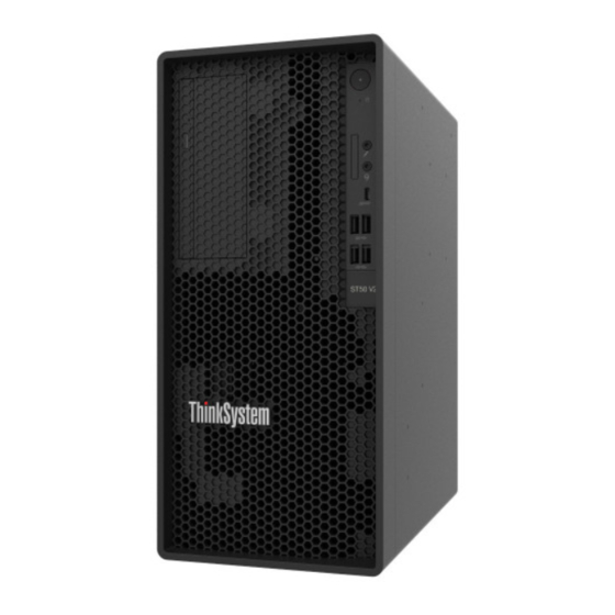
Chapter 1. Introduction The ThinkSystem ST50 V2 server is a 4U tower server designed for performance and expansion for various IT workloads. With the modular design, the server is flexible to be customized for maximum storage capacity or high storage density with selectable input/output options and tiered system management. -
Page 10: Server Form Factor
Scan the QR code with a mobile device and a QR code reader application to get quick access to the Lenovo Service web site for this server. The Lenovo Service web site provides additional information for parts installation and replacement videos, and error codes for server support. - Page 11 • Xeon ® E3–23XX • Pentium Gold For a list of supported processors, see https://static.lenovo.com/us/en/serverproven/ index.shtml Note: Xeon E3–23XX processor without integrated graphics feature does not support the ® KVM redirection functions; GPU is required when such processor is installed. If a processor with integrated graphics feature and a GPU are installed in the system, the integrated graphics feature and the DisplayPorts will be disabled.
- Page 12 • Supports up to two network adapters. Note: For PXE boot application (Preboot eXecution Environment), it is recommended to install a PXE boot supporting Ethernet adapter for best performance. For a list of supported network adapters, see https://static.lenovo.com/us/en/ serverproven/index.shtml ThinkSystem ST50 V2 Maintenance Manual...
- Page 13 • Some Lenovo systems management applications, including XClarity Administrator, XClarity Controller, XClarity Energy Manager, and XClarity Essentials, are not supported by ST50 V2. • For information on the Lenovo XClarity Provisioning Manager Lite, see the LXPM documentation compatible with your server at https://sysmgt.lenovofiles.com/help/ topic/lxpm_frontend/lxpm_product_page.html...
- Page 14 T1000GPU, 1x 500W PSU Heat output Approximate heat output: • Minimum configuration: 443 BTU, 130 W (in BTU per hour and watts) • Maximum configuration: 754 BTU, 221 W (in BTU per hour and watts) ThinkSystem ST50 V2 Maintenance Manual...
-
Page 15: Particulate Contamination
If Lenovo determines that the levels of particulates or gases in your environment have caused damage to the device, Lenovo may condition provision of repair or replacement of devices or parts on implementation of appropriate remedial measures to mitigate such environmental contamination. -
Page 16: Update The Firmware
Update the firmware Go to Lenovo Datacenter Support site for the latest firmware update package. To update the firmware from a flash device, complete the following steps: 1. -
Page 17: Tech Tips
Tech Tips Lenovo continually updates the support website with the latest tips and techniques that you can use to solve issues that your server might encounter. These Tech Tips (also called retain tips or service bulletins) provide procedures to work around issues or solve problems related to the operation of your server. - Page 18 • Start an orderly shutdown using the operating system (if supported by your operating system). • Press the power-on button to start an orderly shutdown (if supported by your operating system). • Press and hold the power button for more than 4 seconds to force a shutdown. ThinkSystem ST50 V2 Maintenance Manual...
-
Page 19: Chapter 2. Server Components
Front thermal sensor Front panel Some crucial key controls, connectors, and LEDs are located on the front panel of the server. The following illustration shows the controls, connectors, and LEDs on the front panel of the server. © Copyright Lenovo 2022, 2022... - Page 20 Two USB 3.2 Gen 2 connectors Headset connector (Windows Client OS only) Notes: • USB 3.2 Gen 1: 5 Gbps = 640 MB/s • USB 3.2 Gen 2: 10 Gbps = 1280 MB/s Power button with power status LED (white) ThinkSystem ST50 V2 Maintenance Manual...
-
Page 21: Side View
Press the power button to turn on the server, or hold it for several seconds to turn the server off when the server cannot be turned off in the operating system. The power status LED helps determine the current power status. Table 5. -
Page 22: Rear View
PCIe slot 1–3 SATA 1–4 connectors PCIe adapter retainer Front fan Cage bar Mono amplifier (speaker) Rear fan Optional components. Rear view Refer this section to identify important components on the rear of the server. ThinkSystem ST50 V2 Maintenance Manual... - Page 23 Figure 6. Rear view Table 8. Rear view Padlock loop Two USB 3.2 Gen1 connectors PCIe slot 1 1 GB RJ45 Ethernet connector PCIe slot 2 DisplayPort 2 connector (Supported by processor with integrated graphic feature only.) PCIe slot 3 DisplayPort 1 connector (Supported by processor with integrated graphic feature only.) Kensington lock...
- Page 24 1. This connector is only supported by Windows Client OS. 2. User may be aware of the low frequency noise via audio port in particular environments. 3. Excessive sound pressure from earphone/headphone can cause hearing damage. ThinkSystem ST50 V2 Maintenance Manual...
-
Page 25: Server Locks
The cable lock also locks the buttons used to remove the server cover. This is the same type of lock used with many notebook computers. You can order an integrated cable lock directly from Lenovo by searching for Kensington at: http://datacentersupport.lenovo.com... -
Page 26: System Board Components
Figure 8. Padlock System board components The illustration in this section shows the component locations on the system board. Figure 9. System board components ThinkSystem ST50 V2 Maintenance Manual... -
Page 27: Raid Adapters
Table 10. Components on the system board Processor power connector 3V battery (CR2032) Note: The 2x2 pins marked in grey are for 300W PSU. Processor SATA 3 connector (drive bay 3) Processor heat sink fan power connector SATA 4 connector (ODD drive) Memory module slot 1 SATA 2 connector (drive bay 2) Memory module slot 2... - Page 28 Any damage to the cable sockets might require replacing the system board. Figure 11. Pressing the release tab to disengage the connector Figure 12. Squeezing the release tabs at both sides to disengage the connector ThinkSystem ST50 V2 Maintenance Manual...
-
Page 29: Cable Routing For Drive Bay 1 And Bay 2
Cable routing for drive bay 1 and bay 2 Read this section to learn about cable routing for the drive in bay 1 and bay 2. Drive bay 1 Figure 13. Cable routing for drive bay 1 Table 11. Cable routing for drive bay 1 Cable From 1st 3.5 or 2.5 HDD SATA cable,... - Page 30 SATA power 2 connector (300 mm + 80 mm) 1 drive power connector Make sure to follow the “Cable routing guidelines” in “Internal cable routing” on page For the system-board connector locations, see “System board components” on page ThinkSystem ST50 V2 Maintenance Manual...
-
Page 31: Cable Routing For Drive Bay 3
Cable routing for drive bay 3 Read this section to learn about cable routing for the drive in bay 3. Figure 15. Cable routing for drive bay 3 Table 13. Cable routing for drive bay 3 Cable From SATA cable 1 latch (520 mm) Bay 3 drive signal connector SATA 3 connector Slim ODD, second 3.5-inch drive... -
Page 32: Cable Routing For Optical Disk Drive
SATA power 1 connector mm + 210 mm + 110 mm) Make sure to follow the “Cable routing guidelines” in “Internal cable routing” on page For the system-board connector locations, see “System board components” on page ThinkSystem ST50 V2 Maintenance Manual... -
Page 33: Cable Routing For The Raid Adapter And Drives
Cable routing for the RAID adapter and drives Read this section to learn about cable routing for the RAID adapter and drives. RAID adapter cable The break lines indicate that part of the cable is hidden in the illustration. Figure 17. Mini SAS HD to 4 SATA 7-pin cable Table 15. - Page 34 ( 300 mm + 210 mm + 110 mm) connector Make sure to follow the “Cable routing guidelines” in “Internal cable routing” on page For the system-board connector locations, see “System board components” on page ThinkSystem ST50 V2 Maintenance Manual...
- Page 35 Cable routing for two drives with the RAID adapter Note: The RAID adapter should be installed in PCIe slot 1. Figure 19. Cable routing for two drives with the RAID adapter Table 17. Cable routing for two drives with the RAID adapter Cable From Bay 1 drive signal...
-
Page 36: Cable Routing For The Power Supply Unit
(15-pin connector for system power) are parts of the same Y-splitter cable. Note: Make sure to follow the “Cable routing guidelines” in “Internal cable routing” on page For the system-board connector locations, see “System board components” on page ThinkSystem ST50 V2 Maintenance Manual... -
Page 37: Cable Routing For The Front Fan And Rear Fan
Cable routing for the front fan and rear fan Read this section to learn about cable routing for the front fan and rear fan. Figure 21. Cable routing for the front fan and rear fan Table 19. Cable routing for the heat sink and fan module From Front fan cable Front fan connector... -
Page 38: Cable Routing For The Heat Sink And Fan
Figure 23. Cable routing for the heat sink and fan module for processor with 95W TDP Table 20. Cable routing for the heat sink and fan module From Processor heat sink fan power connector Heat sink and fan module cable ThinkSystem ST50 V2 Maintenance Manual... - Page 39 Make sure to follow the “Cable routing guidelines” in “Internal cable routing” on page For the system-board connector locations, see “System board components” on page Chapter 2 Server components...
-
Page 40: Cable Routing For The Intrusion Switch
Read this section to learn about cable routing for the intrusion switch. Figure 24. Cable routing for the intrusion switch Table 21. Cable routing for the intrusion switch From Intrusion switch cable Intrusion switch connector For the system-board connector locations, see “System board components” on page ThinkSystem ST50 V2 Maintenance Manual... -
Page 41: Cable Routing For The Thermal Sensor
Cable routing for the thermal sensor Read this section to learn about cable routing for the thermal sensor. Figure 25. Cable routing for the thermal sensor Table 22. Cable routing for the thermal sensor From Thermal sensor cable Thermal sensor connector Note: If applicable, place the thermal sensor cable under the M.2 drive. -
Page 42: Cable Routing For The Mono Amplifier
Table 23. Cable routing for the mono amplifier From Mono amplifier cable Mono amplifier connector Make sure to follow the “Cable routing guidelines” in “Internal cable routing” on page For the system-board connector locations, see “System board components” on page ThinkSystem ST50 V2 Maintenance Manual... -
Page 43: Led
Cable routing for the power button with LED Read this section to learn about cable routing for the power button with LED. Figure 27. Cable routing for the power button with LED Table 24. Cable routing for the power button with LED From Power button with LED cable Power button with LED connector... -
Page 44: Parts List
Tier 1 CRU at your request with no service agreement, you will be charged for the installation. • Tier 2 customer replaceable unit (CRU): You may install a Tier 2 CRU yourself or request Lenovo to install it, at no additional charge, under the type of warranty service that is designated for your server. - Page 45 • Field replaceable unit (FRU): FRUs must be installed only by trained service technicians. • Consumable and Structural parts: Purchase and replacement of consumable and structural parts is your responsibility. If Lenovo acquires or installs a structural component at your request, you will be charged for the service.
- Page 46 Table 25. Parts listing (continued) Consumable Description and Structural Index Tier 1 CRU Tier 2 CRU parts Heat sink and fan module (for √ processor with 95W TDP) √ 3V CMOS battery (CR2032) ThinkSystem ST50 V2 Maintenance Manual...
-
Page 47: Power Cords
Several power cords are available, depending on the country and region where the server is installed. To view the power cords that are available for the server: 1. Go to: http://dcsc.lenovo.com/#/ 2. Click Preconfigured Model or Configure to order. 3. Enter the machine type and model for your server to display the configurator page. - Page 48 ThinkSystem ST50 V2 Maintenance Manual...
-
Page 49: Chapter 3. Hardware Replacement Procedures
– Use a slow lifting force. Never move suddenly or twist when you lift a heavy object. – To avoid straining the muscles in your back, lift by standing or by pushing up with your leg muscles. © Copyright Lenovo 2022, 2022... -
Page 50: System Reliability Guidelines
• All processor sockets must contain either a socket cover or a processor with heat sink. • When more than one processor is installed, fan population rules for each server must be strictly followed. ThinkSystem ST50 V2 Maintenance Manual... -
Page 51: Handling Static-Sensitive Devices
Handling static-sensitive devices Review these guidelines before you handle static-sensitive devices to reduce the possibility of damage from electrostatic discharge. Attention: Prevent exposure to static electricity, which might lead to system halt and loss of data, by keeping static-sensitive components in their static-protective packages until installation, and handling these devices with an electrostatic-discharge wrist strap or other grounding system. -
Page 52: Memory Module Installation Rules
• All memory modules installed should be identical in type and capacity. • Do not mix memory modules with different voltages. • Do not mix low-voltage and regular UDIMMs. (2R memory module only) For a list of supported Memory module slot options, see: https://static.lenovo.com/us/en/serverproven/ index.shtml ThinkSystem ST50 V2 Maintenance Manual... -
Page 53: Cmos Battery (Cr2032) Replacement
Table 27. Memory module installation rules and order for Independent Mode Total Memory channel A Memory channel B memory Slot 3 Slot 4 Slot 1 Slot 2 modules † See the following for the maximum memory speed supported: • Maximum memory speed supported by same memory capacity: –... - Page 54 S004 CAUTION: When replacing the lithium battery, use only Lenovo specified part number or an equivalent type battery recommended by the manufacturer. If your system has a module containing a lithium battery, replace it only with the same module type made by the same manufacturer. The battery contains lithium and can explode if not properly used, handled, or disposed of.
-
Page 55: Install The Cmos Battery (Cr2032)
• To avoid possible danger, make sure to read and follow the safety statements. • Lenovo has designed this product with your safety in mind. The CMOS battery must be handled correctly to avoid possible danger. If you install the CMOS battery, do adhere to the following instructions. - Page 56 S004 CAUTION: When replacing the lithium battery, use only Lenovo specified part number or an equivalent type battery recommended by the manufacturer. If your system has a module containing a lithium battery, replace it only with the same module type made by the same manufacturer. The battery contains lithium and can explode if not properly used, handled, or disposed of.
-
Page 57: Drive And Drive Cage Replacement
A video of this procedure is available at YouTube: https://www.youtube.com/playlist?list=PLYV5R7hVcs- AU3iY3F7lq3qfqr5caGbIu Procedure Step 1. Place the CMOS battery on top of the socket with the positive (+) symbol facing up, and press the battery into the seat until it clicks in place. Figure 31. -
Page 58: Replacement
Attention: The heat sink and processor could be very hot. To avoid burning yourself, wait for a few minutes after turning off the server before you remove the server cover. Step 2. Disconnect every cable from the drive assembly. ThinkSystem ST50 V2 Maintenance Manual... - Page 59 Step 3. Remove the simple-swap drive assembly. Remove the simple-swap drive assembly from drive bay 1 Grasp the retainer handle, and lift the drive assembly out of the drive bay. Figure 33. Removing drive assembly from drive bay 1 Remove the simple-swap drive assembly from drive bay 2 Pinch the retainer handles.
- Page 60 Figure 35. Removing a 3.5-inch drive from the retainer Note: Depending on the configuration, the 3.5-inch drive may be the model in the illustration below. Remove a 2.5-inch drive from the retainer Figure 36. Removing a 2.5-inch drive from the retainer ThinkSystem ST50 V2 Maintenance Manual...
- Page 61 – 2.5-inch simple-swap solid-state drive in drive bay 2 For a complete list of supported optional devices for the server, see https://static.lenovo.com/us/en/ serverproven/index.shtml • If there are more than one drives to be installed, determine installation order based on the following rules: –...
- Page 62 Align the four holes on the drive with the corresponding pins on the retainer; then, fit the drive into the retainer. Note: The drive connectors should face the retainer handles. Install a 3.5-inch drive into the retainer ThinkSystem ST50 V2 Maintenance Manual...
- Page 63 Figure 38. Installing a 3.5-inch drive into the retainer Note: Depending on the configuration, the 3.5-inch drive may be the model in the illustration below. Install a 2.5-inch drive into the retainer Chapter 3 Hardware replacement procedures...
- Page 64 Step 2. Face the retainer handles upward and push the drive assembly into the drive bay. Press the drive assembly firmly to ensure it is seated correctly. Install 3.5-inch drive assembly into drive bay 1 ThinkSystem ST50 V2 Maintenance Manual...
- Page 65 Figure 40. Install 3.5-inch drive assembly into drive bay 1 Install 2.5-inch drive assembly into drive bay 2 Figure 41. Install 2.5-inch drive assembly into drive bay 2 Step 3. Connect the signal and power cable to the system board, see “Internal cable routing”...
- Page 66 White The drives are active. None The drives are not active. 3. Use the Lenovo XClarity Provisioning Manager Lite to configure the RAID if necessary. For more information, see https://sysmgt.lenovofiles.com/help/topic/LXPML/RAID_setup.html Remove the drive cage (bay 1-2) Follow this procedure to remove the drive cage from bay 1 or bay 2.
- Page 67 Note: Remove the bay 2 drive cage first; then, proceed to remove the bay 1 drive cage. Slightly pull out the latch on the bay 2 drive cage to release it from the bay 1 drive cage. Pull the bay 2 drive cage out from the chassis. Figure 42.
- Page 68 About this task Attention: • Read “Safety inspection checklist” on page iv “Installation guidelines” on page 41 to ensure that you work safely. Watch the procedure ThinkSystem ST50 V2 Maintenance Manual...
- Page 69 A video of this procedure is available at YouTube: https://www.youtube.com/playlist?list=PLYV5R7hVcs- AU3iY3F7lq3qfqr5caGbIu Procedure Note: Install the bay 1 drive cage first; then, proceed to install the bay 2 drive cage. Step 1. Install the bay 1 drive cage. Align the bay 1 drive cage to the slots on chassis; then, install it into the chassis. Make sure the drive cage is seated correctly in the chassis.
-
Page 70: Simple-Swap Drive And Drive Cage Replacement (Bay 3)
“Installation guidelines” on page 41 to ensure that you work safely. • Turn off the server and peripheral devices, and disconnect the power cords and all external cables, see “Power off the server” on page ThinkSystem ST50 V2 Maintenance Manual... - Page 71 • If the server is in a rack, remove it from the rack. See “Remove the server from the rails” on page 137. • Remove any locking device that secures the server, such as a Kensington lock or a padlock. •...
- Page 72 RAID array. The drives in a single RAID array must be the same type and the same capacity. See for more details. https://sysmgt.lenovofiles.com/help/topic/LXPML/RAID_setup.html Watch the procedure A video of this procedure is available at YouTube: https://www.youtube.com/playlist?list=PLYV5R7hVcs- AU3iY3F7lq3qfqr5caGbIu Procedure ThinkSystem ST50 V2 Maintenance Manual...
- Page 73 Note: To prevent from damaging the drive with static discharge, do not touch the circuit board on the bottom of the drive. Figure 47. Circuit board on the drive Step 1. Install the 3.5-inch drive to the drive cage. Slightly tear both sides of the retainer apart. Note: Position the drive connectors on the opposite side of the retainer handles.
- Page 74 White The drives are active. None The drives are not active. 5. Use the Lenovo XClarity Provisioning Manager Lite to configure the RAID if necessary. For more information, see https://sysmgt.lenovofiles.com/help/topic/LXPML/RAID_setup.html Remove the drive cage (bay 3) Follow this procedure to remove a simple-swap drive cage from bay 3.
- Page 75 • Remove any locking device that secures the server, such as a Kensington lock or a padlock. • Place the server on its side with the cover up. Watch the procedure A video of this procedure is available at YouTube: https://www.youtube.com/playlist?list=PLYV5R7hVcs- AU3iY3F7lq3qfqr5caGbIu Procedure...
- Page 76 Note: Installing the EMI shielding is required when the original shielding slot on the chassis is vacant. Insert the tabs on the left end of the EMI shielding into the shield slot on the chassis. Push the EMI shielding into the chassis until it snaps into place. ThinkSystem ST50 V2 Maintenance Manual...
- Page 77 Figure 50. Installing the EMI shielding Step 2. Make sure there is no optical drive installed on the optical drive cage. Then, istall the 3.5-inch drive cage to the optical drive cage. Align the four hooks on the optical drive cage with the corresponding hooks on the 3.5-inch drive cage;...
-
Page 78: Optical Drive And Drive Cage Replacement
Step 2. Remove the optical drive from the optical drive cage. Press the latch on the optical drive to release it from the optical drive cage. Slide out the optical drive from the chassis. ThinkSystem ST50 V2 Maintenance Manual... - Page 79 Figure 52. Removing the optical drive Step 3. (Optional) Remove the optical drive retainer. Pull out the retainer to disengage it from the optical drive. Slide the retainer downward, and remove it from the optical drive. Figure 53. Removing optical drive retainer Step 4.
- Page 80 3. If you are instructed to return the component or optional device, follow all packaging instructions, and use any packaging materials for shipping that are supplied to you. Install an optical drive Follow this procedure to install an optical drive. ThinkSystem ST50 V2 Maintenance Manual...
- Page 81 S002 CAUTION: The power-control button on the device and the power switch on the power supply do not turn off the electrical current supplied to the device. The device also might have more than one power cord. To remove all electrical current from the device, ensure that all power cords are disconnected from the power source.
- Page 82 Insert the rest two pins on retainer to the corresponding slots on the optical drive. Figure 57. Installing the retainer to the optical drive Step 3. (Optional) Align the optical drive bezel with the slots on the optical drive; then, insert the bezel into the optical drive. ThinkSystem ST50 V2 Maintenance Manual...
- Page 83 Figure 58. Installing the optical drive bezel Step 4. Install the optical drive. From outside of the chassis, insert the optical drive into the chassis. Slide the optical drive inward until the latch snaps into place. Figure 59. Installing the optical drive Step 5.
- Page 84 If applicable, remove the optical drive, see “Remove an optical drive” on page Step 2. Remove the optical drive cage from the chassis. Rotate the handle on the optical drive cage. Lift the optical drive cage out from the chassis. ThinkSystem ST50 V2 Maintenance Manual...
- Page 85 Figure 60. Removing the optical drive cage After you finish 1. If applicable, replace the 3.5-inch drive cage or replace the 3.5-inch drive, see “Simple-swap drive and drive cage replacement (bay 3)” on page 2. If you are instructed to return the component or optional device, follow all packaging instructions, and use any packaging materials for shipping that are supplied to you.
- Page 86 Ensure the optical drive cage is seated correctly; then, rotate the optical drive cage handle toward the front of the chassis to secure the optical drive cage into place. ThinkSystem ST50 V2 Maintenance Manual...
-
Page 87: Fan Replacement
Figure 61. Installing the optical drive cage Step 4. If applicable, connect the signal and power cable of the 3.5-inch drive to the system board, see “Internal cable routing” on page Procedure 1. To install an optical drive, see “Install an optical drive” on page 2. - Page 88 (Removing the front fan only) Remove the front bezel, see “Remove the front bezel” on page Step 2. Disconnect the fan cable from the system board. ThinkSystem ST50 V2 Maintenance Manual...
-
Page 89: Install The Fan (Front And Rear)
Step 3. Remove the front fan or rear fan from the chassis. From the outside of the chassis, cut off the four rubber mounts that secure the fan to the chassis. Slide the fan away from the chassis; then, lift it out of the chassis. Figure 62. - Page 90 Figure 63. Installing the front fan or the rear fan Note: Make sure the rubber mounts are fully pulled out of the holes to secure the fans steadily to the chassis. ThinkSystem ST50 V2 Maintenance Manual...
-
Page 91: Front Bezel Replacement
Figure 64. Front fan and rear fan rubber mounts installation Step 2. Connect the fan cable to the system board, see “Internal cable routing” on page After you finish 1. (Removing the front fan only) Reinstall the front bezel, see “Install the front bezel”... - Page 92 • Remove any locking device that secures the server, such as a Kensington lock or a padlock. • Place the server on its side with the cover up. Watch the procedure A video of this procedure is available at YouTube: https://www.youtube.com/playlist?list=PLYV5R7hVcs- AU3iY3F7lq3qfqr5caGbIu ThinkSystem ST50 V2 Maintenance Manual...
-
Page 93: Install The Front Bezel
Procedure Step 1. Make preparation for this task. Remove the server cover, see “Remove the server cover” on page 143. Note: The heat sink and processor could be very hot. To avoid burning yourself, wait for a few minutes after turning off the server before you remove the server cover. Step 2. -
Page 94: Front Panel Replacement
Proceed to complete the parts replacement, see “Complete the parts replacement” on page 158. Front panel replacement Follow this procedure to remove and install the front panel. Remove the front panel Follow this procedure to remove the front panel. ThinkSystem ST50 V2 Maintenance Manual... - Page 95 S002 CAUTION: The power-control button on the device and the power switch on the power supply do not turn off the electrical current supplied to the device. The device also might have more than one power cord. To remove all electrical current from the device, ensure that all power cords are disconnected from the power source.
- Page 96 Figure 67. Disconnecting the power button from the system board Step 3. Remove the screw the secures the front bezel to the chassis. ThinkSystem ST50 V2 Maintenance Manual...
- Page 97 Figure 68. Removing the screw the secures the front bezel to the chassis Step 4. Remove the front panel. Rotate the left end of the front panel away from the chassis. Remove the front panel from the chassis. Chapter 3 Hardware replacement procedures...
-
Page 98: Install The Front Panel
The device also might have more than one power cord. To remove all electrical current from the device, ensure that all power cords are disconnected from the power source. About this task Attention: ThinkSystem ST50 V2 Maintenance Manual... - Page 99 1. Read “Safety inspection checklist” on page iv “Installation guidelines” on page 41 to ensure that you work safely. 2. Touch the static-protective package that contains the component to any unpainted metal surface on the server; then, remove it from the package and place it on a static-protective surface. Watch the procedure A video of this procedure is available at YouTube: https://www.youtube.com/playlist?list=PLYV5R7hVcs-...
-
Page 100: Heat Sink And Fan Module Replacement
Follow this procedure to remove and install the heat sink and fan module. Remove the heat sink and fan module (trained technician only) Follow this procedure to remove the heat sink and fan module. This procedure must be executed by a trained technician. ThinkSystem ST50 V2 Maintenance Manual... - Page 101 S002 CAUTION: The power-control button on the device and the power switch on the power supply do not turn off the electrical current supplied to the device. The device also might have more than one power cord. To remove all electrical current from the device, ensure that all power cords are disconnected from the power source.
- Page 102 2. Always keep the four screws attached to the heat sink and fan module. 3. Do not touch the thermal grease while handling the heat sink and fan module. Loosening the screws on the heat sink and fan module for processor with TDP lower than ThinkSystem ST50 V2 Maintenance Manual...
- Page 103 Figure 73. Loosening the screws on the heat sink and fan module for processor with TDP lower than 95W Loosening the screws on the heat sink and fan module for processor with 95W TDP Figure 74. Loosening the screws on the heat sink and fan module for processor with 95W TDP Step 5.
-
Page 104: Install The Heat Sink And The Fan Module
Align the four screws on the heat sink and fan assembly with the corresponding screw holes on the system board. Make sure the fan cable is close to the heat sink fan connector, see “System board components” on page ThinkSystem ST50 V2 Maintenance Manual... - Page 105 Step 3. Tighten screw 1 and 2 first, then tighten screw 3 and 4. Partially tighten screw 1. Fully tighten screw 2. Fully tighten screw 1. Partially tighten screw 3. Fully tighten screw 4. Fully tighten screw 3. Note: Do not touch the thermal grease while handling the heat sink and fan module. Tightening the screws on the heat sink and fan module for processor with TDP lower than Figure 75.
- Page 106 Figure 77. Installing the heat sink fan to the rear of the chassis Step 5. Connect the heat sink fan cable to the system board, see “Internal cable routing” on page ThinkSystem ST50 V2 Maintenance Manual...
-
Page 107: Intrusion Switch Replacement
After you finish 1. If necessary, reinstall the optical drive cage, see “Install the optical drive cage” on page 2. Proceed to complete the parts replacement, see “Complete the parts replacement” on page 158. Intrusion switch replacement The intrusion switch generates an event in the system event log (SEL) when the server cover is not properly installed. - Page 108 Figure 78. Disconnecting the intrusion switch cable from system board Step 3. Remove the intrusion switch. Remove the screw that secures the intrusion switch to the chassis. Remove the intrusion switch from the chassis. ThinkSystem ST50 V2 Maintenance Manual...
-
Page 109: Install The Intrusion Switch
Figure 79. Removing the intrusion switch After you finish 1. Install a new intrusion switch, see “Install the intrusion switch” on page 101. 2. If you are instructed to return the component or optional device, follow all packaging instructions, and use any packaging materials for shipping that are supplied to you. - Page 110 Fasten the screw to secure the intrusion switch to the chassis. Figure 81. Installing the intrusion switch Step 3. Connect the intrusion switch cable to the system board, see “Internal cable routing” on page After you finish ThinkSystem ST50 V2 Maintenance Manual...
-
Page 111: M.2 Drive And Retainer Replacement
Proceed to complete the parts replacement, see “Complete the parts replacement” on page 158. M.2 drive and retainer replacement Follow this procedure to remove and install the M.2 drive and the M.2 drive retainer. Remove an M.2 drive Follow this procedure to remove an M.2 drive. S002 CAUTION: The power-control button on the device and the power switch on the power supply do not turn off the... - Page 112 Step 3. Remove the M.2 drive. Lift the retainer post away from the M.2 drive retainer. Rotate the rear end of the M.2 drive to an angle, and remove the M.2 drive from the system board. ThinkSystem ST50 V2 Maintenance Manual...
-
Page 113: Install An M.2 Drive
Figure 83. Removing the M.2 drive After you finish 1. Install a new M.2 drive if necessary, see “Install an M.2 drive” on page 105. 2. If you are instructed to return the component or optional device, follow all packaging instructions, and use any packaging materials for shipping that are supplied to you. -
Page 114: Remove The M.2 Drive Retainer
“Install a simple-swap drive (bay 1-2)” on page 2. Proceed to complete the parts replacement, see “Complete the parts replacement” on page 158. Remove the M.2 drive retainer Follow this procedure to remove the M.2 drive retainer. ThinkSystem ST50 V2 Maintenance Manual... - Page 115 S002 CAUTION: The power-control button on the device and the power switch on the power supply do not turn off the electrical current supplied to the device. The device also might have more than one power cord. To remove all electrical current from the device, ensure that all power cords are disconnected from the power source.
- Page 116 “Install the M.2 drive retainer” on page 109. 2. If you are instructed to return the component or optional device, follow all packaging instructions, and use any packaging materials for shipping that are supplied to you. ThinkSystem ST50 V2 Maintenance Manual...
-
Page 117: Install The M.2 Drive Retainer
Install the M.2 drive retainer Follow this procedure to install the M.2 drive retainer. S002 CAUTION: The power-control button on the device and the power switch on the power supply do not turn off the electrical current supplied to the device. The device also might have more than one power cord. To remove all electrical current from the device, ensure that all power cords are disconnected from the power source. - Page 118 3. Proceed to complete the parts replacement, see “Complete the parts replacement” on page 158. ThinkSystem ST50 V2 Maintenance Manual...
-
Page 119: Memory Module Replacement
Memory module replacement Follow this procedure to remove and install a memory module. Remove a memory module Follow this procedure to remove a memory module S002 CAUTION: The power-control button on the device and the power switch on the power supply do not turn off the electrical current supplied to the device. -
Page 120: Install A Memory Module
About this task Important: Ensure that you consider and follow the memory module installation rules when performing the operation, see “Memory module installation rules” section in Setup Guide. ThinkSystem ST50 V2 Maintenance Manual... - Page 121 Attention: • Read “Safety inspection checklist” on page iv “Installation guidelines” on page 41 to ensure that you work safely. • Touch the static-protective package that contains the component to any unpainted metal surface on the server; then, remove it from the package and place it on a static-protective surface. Memory modules are sensitive to static discharge and require special handling.
- Page 122 ThinkSystem ST50 V2 Maintenance Manual...
-
Page 123: Mono Amplifier (Speaker) Replacement
Step 3. Align the memory module with the slot; then, press the memory module into the slot with even pressure on both ends of the memory module until the retaining clips snap into the locked position. Note: Make sure that the small tabs on the retaining clips engage with the notches on the memory module. - Page 124 Note: The heat sink and processor could be very hot. To avoid burning yourself, wait for a few minutes after turning off the server before you remove the server cover. Step 2. Disconnect the mono amplifier cable from the system board. ThinkSystem ST50 V2 Maintenance Manual...
- Page 125 Figure 91. Disconnecting the mono amplifier cable Step 3. Remove the mono amplifier. Remove the screw that secures the mono amplifier to the chassis. Slide out the mono amplifier from the bracket, and remove it from the chassis. Figure 92. Removing the mono amplifier After you finish Chapter 3 Hardware replacement procedures...
-
Page 126: Install The Mono Amplifier (Speaker)
A video of this procedure is available at YouTube: https://www.youtube.com/playlist?list=PLYV5R7hVcs- AU3iY3F7lq3qfqr5caGbIu Procedure Step 1. Install the mono amplifier. Insert the mono amplifier into the bracket on the inside of the chassis. Fasten the screw to secure the mono amplifier to the chassis. ThinkSystem ST50 V2 Maintenance Manual... -
Page 127: Pcie Adapter Replacement
This server comes with three PCIe slots. The adapter can be Ethernet, host bus, RAID, graphics, or any other types that are supported, but the installation and removal procedures are the same. Note: For a list of the supported PCIe adapters, see: https://static.lenovo.com/us/en/serverproven/index.shtml Remove a PCIe adapter Follow this procedure to remove a PCIe adapter. - Page 128 Note: The PCIe adapter might be clamped by the slot tightly. In this case, gently and evenly shake the PCIe adapter until the clamping force from the connector is significantly reduced and the adapter becomes easily removable. ThinkSystem ST50 V2 Maintenance Manual...
- Page 129 Figure 94. Removing a PCIe adapter After you finish 1. Install another PCIe adapter if necessary, see “Install a PCIe adapter” on page 122. Otherwise, install a bracket to cover the vacancy on the chassis, and close the retainer. Chapter 3 Hardware replacement procedures...
-
Page 130: Install A Pcie Adapter
About this task Attention: • Read “Safety inspection checklist” on page iv “Installation guidelines” on page 41 to ensure that you work safely. ThinkSystem ST50 V2 Maintenance Manual... - Page 131 PCIe slot 3 (x4). • For a list of the supported PCIe adapters, see https://static.lenovo.com/us/en/serverproven/index.shtml • The PCIe adapter might look different from the illustration. • Make sure to read and follow the documentation that comes with the PCIe adapter.
- Page 132 Align the PCIe adapter to the slot; then, gently press both ends of the PCIe adapter until it is securely seated in the slot with the retaining clip clicks into the locked position. Rotate the PCIe adapter retainer towards the chassis until it snaps into locked position. ThinkSystem ST50 V2 Maintenance Manual...
-
Page 133: Power Button With Led Replacement
Figure 97. Installing a PCIe adapter Step 4. Connect the PCIe adapter cables. For more information on RAID adapter cable routing, see “Internal cable routing” on page After you finish Proceed to complete the parts replacement, see “Complete the parts replacement” on page 158. - Page 134 “Install the power button with LED” on page 127. 2. If you are instructed to return the component or optional device, follow all packaging instructions, and use any packaging materials for shipping that are supplied to you. ThinkSystem ST50 V2 Maintenance Manual...
-
Page 135: Install The Power Button With Led
Install the power button with LED Follow this procedure to install the power button with LED. S002 CAUTION: The power-control button on the device and the power switch on the power supply do not turn off the electrical current supplied to the device. The device also might have more than one power cord. To remove all electrical current from the device, ensure that all power cords are disconnected from the power source. -
Page 136: Power Supply Unit Replacement
The device also might have more than one power cord. To remove all electrical current from the device, ensure that all power cords are disconnected from the power source. ThinkSystem ST50 V2 Maintenance Manual... - Page 137 S035 CAUTION: Never remove the cover on a power supply or any part that has this label attached. Hazardous voltage, current, and energy levels are present inside any component that has this label attached. There are no serviceable parts inside these components. If you suspect a problem with one of these parts, contact a service technician.
- Page 138 Press the release tab to disengage the power supply from the chassis. Slide out the power supply unit; then, lift it out of the chassis. Figure 101. Removing the power supply unit After you finish ThinkSystem ST50 V2 Maintenance Manual...
-
Page 139: Install The Power Supply Unit
1. Install another power supply unit, see “Install the power supply unit” on page 131. 2. If you are instructed to return the component or optional device, follow all packaging instructions, and use any packaging materials for shipping that are supplied to you. Install the power supply unit Follow this procedure to install the power supply unit. - Page 140 Figure 102. Installing the power supply to the chassis Step 2. From outside of the chassis, fasten the four screws to secure the power supply unit to the chassis. ThinkSystem ST50 V2 Maintenance Manual...
-
Page 141: Processor Replacement (Trained Technician Only)
Figure 103. Securing the power supply units to the chassis Step 3. Connect the processor and system power cables to the system board, see “Internal cable routing” on page After you finish 1. Reinstall bay 1 drive cage and the 3.5-inch drive, see “Simple-swap drive and drive cage (bay 1-2) replacement”... - Page 142 Hold the processor by both sides and gently lift it away from the processor socket. Attention: 1. Do not touch the gold contacts on the bottom of the processor. 2. Keep the processor socket clean from any object to prevent possible damages. ThinkSystem ST50 V2 Maintenance Manual...
-
Page 143: Only)
135. 2. Package the defective processor that was removed, and return it to Lenovo. To prevent any shipping damage, reuse the packaging of the new processor, and follow all available packaging instructions. • Install the processor that you removed to the replacement system board. - Page 144 A video of this procedure is available at YouTube: https://www.youtube.com/playlist?list=PLYV5R7hVcs- AU3iY3F7lq3qfqr5caGbIu Procedure Step 1. Hold the processor by both sides, and align the following: 1. Align the small notches on the processor to the tabs on the socket. ThinkSystem ST50 V2 Maintenance Manual...
-
Page 145: Server Replacement
2. Align the small triangle of the processor to the beveled corner on the socket. Then, gently lower the processor evenly into the socket. Figure 106. Installing the processor Step 2. Close the processor retainer, and push the handle to the locked position. Figure 107. - Page 146 A video of this procedure is available at YouTube: https://www.youtube.com/playlist?list=PLYV5R7hVcs- AU3iY3F7lq3qfqr5caGbIu Procedure Note: Your system might looks slightly different from the illustration below. Step 1. Remove the two M6 x 16 screws on the front of the rack cabinet. ThinkSystem ST50 V2 Maintenance Manual...
-
Page 147: Install The Server To The Rails
Figure 108. Removing the screws on the front of the rack cabinet Step 2. Remove the server from the rails. Slide and pull the rack server tray out of the rack cabinet. Lift the server out of the tray. Figure 109. Removing the server from the rails After you finish 1. - Page 148 Note: To install rails to rack, see the Rail Installation Guide at https://thinksystem.lenovofiles.com/help/topic/ rail_options/rail_options_tower_servers.html Watch the procedure A video of this procedure is available at YouTube: https://www.youtube.com/playlist?list=PLYV5R7hVcs- AU3iY3F7lq3qfqr5caGbIu Procedure Step 1. Install the four brackets to the tray as illustrated. ThinkSystem ST50 V2 Maintenance Manual...
- Page 149 Figure 110. Installing the brackets to the tray Step 2. Install the four rubber safety pads to the tray as illustrated. Figure 111. Installing the rubber safety pads to the tray Step 3. Orient the server to have the server cover facing up and the front bezel facing the front of the rails; then, align the server with the brackets and the tab on the front of the tray, and gently place the server on the tray.
- Page 150 Gently slide and push the tray into the rack cabinet. Figure 113. Installing the server into the rack cabinet Step 5. Secure the tray with two M6 x 16 screws to the front of the rack cabinet. ThinkSystem ST50 V2 Maintenance Manual...
-
Page 151: Server Cover Replacement
Figure 114. Securing the tray with screws After you finish Proceed to complete the parts replacement, see “Complete the parts replacement” on page 158. Server cover replacement Follow this procedure to remove and install the server cover. Remove the server cover Follow this procedure to remove the server cover. - Page 152 • For proper cooling, always install the server cover before powering on the server. Operating the server without the cover properly installed might result in server component damage. ThinkSystem ST50 V2 Maintenance Manual...
- Page 153 Figure 115. Removing the serve cover Step 3. (Optional) Remove the cage bar. Remove the optical drive cage first, see “Remove the optical drive cage” on page 75; then, proceed to the following procedures. Push the latch on the cage bar until the cage bar is disengaged from the chassis. Rotate the cage bar and remove it from the chassis.
-
Page 154: Install The Server Cover
Note: A new server cover comes without a service label attached. If you need a service label, order it together with the new server cover. The service label is free of charge. Watch the procedure ThinkSystem ST50 V2 Maintenance Manual... - Page 155 A video of this procedure is available at YouTube: https://www.youtube.com/playlist?list=PLYV5R7hVcs- AU3iY3F7lq3qfqr5caGbIu Procedure Step 1. (Optional) Install the cage bar. Insert the tabs on cage bar to the slots on the rear side of the chassis. Align the tabs on the other end of the cage bar to the slots on the front side of the chassis, and rotate the cage bar toward the front of the chassis until the cage bar is secured in place.
-
Page 156: System Board Replacement
The device also might have more than one power cord. To remove all electrical current from the device, ensure that all power cords are disconnected from the power source. About this task ThinkSystem ST50 V2 Maintenance Manual... - Page 157 Important: Record all the settings in the Setup Utility, as you might have to re-enter these settings after replacing the system board. Attention: • Read “Safety inspection checklist” on page iv “Installation guidelines” on page 41 to ensure that you work safely.
-
Page 158: Install The System Board
Install the system board (trained technician only) Follow this procedure to install the system board. This procedure must be executed by a trained technician. ThinkSystem ST50 V2 Maintenance Manual... - Page 159 S002 CAUTION: The power-control button on the device and the power switch on the power supply do not turn off the electrical current supplied to the device. The device also might have more than one power cord. To remove all electrical current from the device, ensure that all power cords are disconnected from the power source.
-
Page 160: Only)
15. Important Update the system firmware and device driver. • Go to https://datacentersupport.lenovo.com/tw/en/products/servers/thinksystem/st50v2/downloads/ to see the latest firmware and driver updates for your server. driver-list/ • Go to “Update the firmware” on page 8 for more information on firmware updating tools. ThinkSystem ST50 V2 Maintenance Manual... -
Page 161: Thermal Sensor Replacement
VPD (Vital Product Data) must be updated after the system board is replaced. Step 1. Insert a USB flash drive to the server, and format it. Step 2. Go to https://datacentersupport.lenovo.com/tw/en/products/servers/thinksystem/st50v2/downloads/ . Select Software and Utilities, and download The uEFI VPD SMBIOS Information Update driver-list/ Utility. Step 3. - Page 162 Remove the front fan, see “Remove the fan (front and rear)” on page If applicable, remove the M.2 drive, see “Remove an M.2 drive” on page 103. Step 2. Disconnect the thermal sensor cable from the system board. ThinkSystem ST50 V2 Maintenance Manual...
- Page 163 Figure 123. Disconnecting the thermal sensor cable Step 3. Remove the thermal sensor. Press the release tab on the thermal sensor to release it from the chassis. Remove the thermal sensor from the chassis. Figure 124. Removing the thermal sensor Chapter 3 Hardware replacement procedures...
-
Page 164: Install The Thermal Sensor
From the inside of the chassis, attach the end of the thermal sensor to the corresponding slot on the front of the chassis. From inside of the chassis, push the thermal sensor into the slot. Make sure the thermal sensor is secured in place. ThinkSystem ST50 V2 Maintenance Manual... - Page 165 Figure 125. Installing the thermal sensor Step 2. Connect the thermal sensor cable to the system board. To locate the connector on the system board, see “Internal cable routing” on page Figure 126. Connecting the thermal sensor cable After you finish Chapter 3 Hardware replacement procedures...
-
Page 166: Complete The Parts Replacement
7. Update the server configuration if necessary. • Go to https://datacentersupport.lenovo.com/tw/en/products/servers/thinksystem/st50v2/downloads/ to see the latest firmware and driver updates for your server. driver-list/ • Go to “Update the firmware” on page 8 for more information on firmware updating tools. ThinkSystem ST50 V2 Maintenance Manual... -
Page 167: Chapter 4. Problem Determination
1. Check in Setup Utility and make sure all the installed components are enabled. 2. Make sure the firmware of the installed components are the latest version. 3. Turn off the server. 4. Ensure that the server is cabled correctly. © Copyright Lenovo 2022, 2022... -
Page 168: List Of Post Error Messages
• Any external devices • Surge-suppressor device (on the server) • Printer, mouse, and non-Lenovo devices • Each adapter • Storage drives • One memory module at a time until you reach the minimum configuration that is supported for the... - Page 169 This error message will be displayed if one of the following malfunctions occurs: 1. Heat sink fan failure 2. Front fan failure (Aux fan failure) The front fan is shown as Aux Fan in BIOS Setup Utility. To see the Aux Fan, go to Setup Utility, select Main ➙...
- Page 170 This error will be displayed for at least five seconds with four one-second beeps before the next boot. Remove some PCIe adapters in Setup Utility to solve this error. ThinkSystem ST50 V2 Maintenance Manual...
-
Page 171: Resolving Suspected Power Problems
Resolving suspected power problems Power problems can be difficult to solve. For example, a short circuit can exist anywhere on any of the power distribution buses. Usually, a short circuit will cause the power subsystem to shut down because of an overcurrent condition. -
Page 172: Troubleshooting By Symptom
2. Make sure the power cord is securely connected to the server and to a working electrical outlet. Disconnect and reconnect or replace the server power cord. 3. Remove and reinstall the power supply. If the problem persists, replace the power supply. ThinkSystem ST50 V2 Maintenance Manual... -
Page 173: Memory Problems
Remove and install the DIMM if there is any. 3. If the server comes with Lenovo XClarity Provisioning Manager Lite, go to Diagnostics ➙ Memory test to perform diagnostics on the DIMMs. Replace the DIMM that is displayed as faulty. Otherwise, skip to the next step. -
Page 174: Hard Disk Drive Problems
Setup Utility and select Security ➙ System Event Log ➙ View System Event Log. 2. If the server comes with Lenovo XClarity Provisioning Manager Lite, go to Diagnostics ➙ HDD test to perform diagnostics on the drives. Replace the drive that is displayed as faulty. Otherwise, skip to the next step. -
Page 175: Monitor And Video Problems
1. If you have installed new DIMMs recently, make sure the capacity of the new DIMMs are the same as the previously installed ones. If not, remove the newly installed DIMMs, and power on the server again. 2. If a graphical adapter is installed, wait for a while as it takes about three minutes before Lenovo logo is displayed. -
Page 176: Optional-Device Problems
“PCIe adapter is not recognized or is not functioning” on page 168 • “A Lenovo optional device that worked previously does not work now. ” on page 169 • “A Lenovo optional device that was just installed does not work.” on page 169 •... -
Page 177: Intermittent Problems
• If it fails, remove another PCIe adapter and restart the server again. A Lenovo optional device that was just installed does not work. Complete the following steps until the problem is solved. -
Page 178: Network Problems
3. Remove and reinstall the network adapter. 4. Turn off the server and disconnect it from the power source; then, wait 10 seconds before restarting the server. 5. If the problem recurs, replace the network adapter. ThinkSystem ST50 V2 Maintenance Manual... -
Page 179: Observable Problems
1. Make sure that the server supports the processor. To view processor details, go to Setup Utility and select Main ➙ System Summary. To determine if the processor is supported for the server, see https://static.lenovo.com/us/en/ serverproven/index.shtml 2. (Trained technician only) Make sure that the processor is installed properly. -
Page 180: Software Problems
• If the system does restart successfully, add the devices that are removed one at a time, and restart the server after each addition until the problem occurs. Replace the device that causes the problem. • If the system fails to restart, there might be a problem with the system board. Call Lenovo support. Unusual smell Complete the following steps until the problem is solved. - Page 181 1. To determine whether the problem is caused by the software, make sure that: • The server has the minimum memory that is needed to use the software. For memory requirements, see the information that comes with the software. Note: If you have just installed an adapter or memory, the server might have a memory-address conflict.
- Page 182 ThinkSystem ST50 V2 Maintenance Manual...
-
Page 183: Chapter 5. Hardware Disassembling For Recycle
Failing to release them before removing the cables will damage the cable connectors on the system board. Any damage to the cable connectors may require system board replacement. Step 3. Remove the system board. See “Remove the system board (trained technician only)” on page 148. © Copyright Lenovo 2022, 2022... - Page 184 After disassembling the server, recycle the unit in compliance with local regulations. ThinkSystem ST50 V2 Maintenance Manual...
-
Page 185: Appendix A. Getting Help And Technical Assistance
Appendix A. Getting help and technical assistance If you need help, service, or technical assistance or just want more information about Lenovo products, you will find a wide variety of sources available from Lenovo to assist you. On the World Wide Web, up-to-date information about Lenovo systems, optional devices, services, and support are available at: http://datacentersupport.lenovo.com... -
Page 186: Contacting Support
Gathering information needed to call Support If you believe that you require warranty service for your Lenovo product, the service technicians will be able to assist you more efficiently if you prepare before you call. You can also see http:// for more information about your product warranty. -
Page 187: Appendix B. Notices
Lenovo representative for information on the products and services currently available in your area. Any reference to a Lenovo product, program, or service is not intended to state or imply that only that Lenovo product, program, or service may be used. Any functionally equivalent product, program, or service that does not infringe any Lenovo intellectual property right may be used instead. -
Page 188: Trademarks
(TBW). A device that has exceeded this limit might fail to respond to system-generated commands or might be incapable of being written to. Lenovo is not responsible for replacement of a device that has exceeded its maximum guaranteed number of program/erase cycles, as documented in the Official Published Specifications for the device. -
Page 189: Electronic Emission Notices
Electronic emission notices When you attach a monitor to the equipment, you must use the designated monitor cable and any interference suppression devices that are supplied with the monitor. Additional electronic emissions notices are available at: http://thinksystem.lenovofiles.com/help/index.jsp Taiwan BSMI RoHS declaration Taiwan import and export contact information Contacts are available for Taiwan import and export information. - Page 190 ThinkSystem ST50 V2 Maintenance Manual...
Need help?
Do you have a question about the ThinkSystem ST50 V2 and is the answer not in the manual?
Questions and answers