
Related Manuals for Megger DLRO10


Summary of Contents for Megger DLRO10
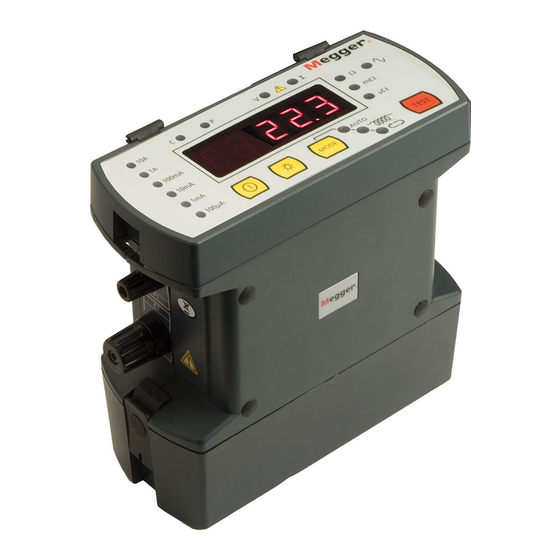
- Page 1 DLRO10 and DLRO 10X DLRO10 and DLRO10X Digital Low Resistance Ohmmeter Digital Low Resistance Ohmmeter User Guide User Guide...
-
Page 2: Table Of Contents
Symbols used on the instrument 4.11 Storage 2. GENERAL DESCRIPTION ..............6 4.12 Range Menu 3. General Operation - DLRO10 .............6 4.13 Entering Notes In The Memo Screen Adjust the brightness control to a comfortable level. 4.14 Test Result Storage Test Current Indicators 4.15... - Page 3 10. ACCESSORIES ................22 11. REPAIR AND WARRANTY ............24 11.1 Instrument Repair and Spare Parts 11.2 Approved Repair Companies 11.3 Returning an Instrument for Repair 11.4 Declaration of Conformity 11.5 End of life disposal 11.5.1 WEEE 11.5.2 Batteries www.megger.com DLRO10 and DLRO10X...
-
Page 4: Safety Warnings
Disconnecting an inductive load while current is still flowing will cause a high voltage arc, which is a danger to both the user and the item under test. Although the DLRO10 and DLRO10X are not designed as transformer ohmmeters the DLRO10 is fitted with a DISCHARGE lamp, marked ‘I’, which ƒ... -
Page 5: Symbols Used On The Instrument
Caution: Refer to accompanying notes Equipment protected throughout by Double or reinforced Insulation (Class II) Equipment complies with current UKCA directives Equipment complies with current EU Directives Do not dispose of in the normal waste stream www.megger.com DLRO10 and DLRO10X... -
Page 6: General Description
The measured value of resistance is output to the instrument display with indication of the units, μΩ, mΩ or Ω. The DLRO10 uses a large LED display and indicators to display the value and units respectively, while the DLRO10X contains all the information on a clear colour display. -
Page 7: Noise Lamp
To turn your DLRO10X on, press the On/Off button for approximately 1 second. Press again to turn the instrument off. If the instrument is not used for 5 minutes it will be turned off automatically. www.megger.com DLRO10 and DLRO10X... -
Page 8: Dlro10X Main Menu Screen
CIRCUIT” if both circuits are inadequate. Check the contacts, since a measurement to the main menu screen. cannot be made if any of these messages is visible on the display. www.megger.com DLRO10 and DLRO10X... -
Page 9: Test Menu
Allows the recall of stored results to the display or a PC. Recalls each test, in sequence, to the instrument display starting with the latest stored result. Use the cursor control Up and Down controls to step later or earlier respectively through the stored results. www.megger.com DLRO10 and DLRO10X... -
Page 10: Download
Enter until the ENABLED / DISABLED choice is shown at which time you may AVERAGE RESISTANCE SELECTED CURRENT change the selection. UPPER LIMIT * LOWER LIMIT * PASS/FAIL * *The last three lines will only appear if passbands have been set www.megger.com DLRO10 and DLRO10X... -
Page 11: Set Clock
4 days by an internal backup battery. When a charged battery pack is refitted, the backup battery will recharge to full capacity within 1 week. www.megger.com DLRO10 and DLRO10X... -
Page 12: Range Menu
The Main Menu screen will show the active current range beneath the RANGE heading. There is a quick access menu that can be accessed using the numbers keys to set the maximum test current as follows:- www.megger.com DLRO10 and DLRO10X... -
Page 13: Test Result Storage
The keys marked 1 - 9 and 0 produce that number when pressed. Press the respective key briefly to enter the desired number. Pressing the blue key marked 9/A changes the function of the keyboard between upper/lower alpha and numeric modes. www.megger.com DLRO10 and DLRO10X... -
Page 14: Test Modes
At the end of each test, DLRO10 will display the average of the values obtained with on the DLRO10, or by using the inductive mode on the DLRO10X. -
Page 15: Undirectional Mode
6. TEST TECHNIQUES and APPLICATIONS At the end of the test both instruments will display the measured resistance, the DLRO10 will flash the relevant current lamp while the DLRO10X will display the test Testing Using Duplex Test Leads Fitted With Indicator Lamps current used on the display. -
Page 16: Testing Using Duplex Handspikes Or Individual Leads
If using Duplex Handspikes ensure that the probe marked P is inside the C probes. to 300 mΩ). This will reduce the generation of internal heat. Note: When used on hazardous voltages Megger DH6 test leads must be used. Test Sequence Pressing the TEST button starts the test sequence. -
Page 17: Battery Module And Care
DLRO or separate, press the Battery Condition Button. The Battery State indicator will light between 1 and 10 segments signifying between 10% and 100% charge respectively. After a few seconds this display will automatically go out. A single flashing LED indicates less than 10% charge. www.megger.com DLRO10 and DLRO10X... -
Page 18: The Battery State Indicator
Connecting to greater than 15 volts can cause permanent damage to the battery module. The DLRO10 and DLRO10X can also be powered from a mains / line power supply unit the DLRO10LPU. This is available as an accessory, details can be found in the Accessories section of this user guide www.megger.com... -
Page 19: Specifications
Voltmeter Input Impedance > 200 kΩ Hum Rejection Less than 1% ± 20 digits additional error with 100 mV peak 50/60 Hz. on the potential leads. Warning will show if hum or noise exceeds this level. www.megger.com DLRO10 and DLRO10X... - Page 20 245 x 237 x 100 mm (9.6 x 9.3 x 4 inch) Without Battery 171 x 237 x 100 mm (6.7 x 9.3 x 4 inch) Weight With Battery 2.46 kg (5.42 lb) Without Battery 1.48 kg (3.26 lb) www.megger.com DLRO10 and DLRO10X...
-
Page 21: Trouble Shooting
Checksum Failure in battery backed RAM. This can occur if the main Recharge the main battery or replace it with a charged one. Switch the battery module and the backup battery become completely exhausted. instrument on. Calibration constants will be retrieved from EEPROM. www.megger.com DLRO10 and DLRO10X... -
Page 22: Accessories
10. ACCESSORIES DLRO10LPU line power unit The DLRO10 and DLRO10X may be also powered from an optional Standard Accessories supplied with all instrument. mains / line power supply unit the DLRO10LPU. This unit is simply fitted to the instrument in place of the standard battery pack. - Page 23 Single handspikes (2) for potential measurement. 2 m/7 ft 242021-7 5.5 m/18 ft 242021-18 9 m/30 ft 242021-30 Current clips (2) for current connections. 2 m/7 ft 242041-7 5.5 m/18 ft 242041-18 9 m/30 ft 242041-30 www.megger.com DLRO10 and DLRO10X...
-
Page 24: Repair And Warranty
11.5.1 WEEE England. U.S.A. The crossed out wheeled bin placed on the Megger products is a reminder not to Tel: +44 (0) 1304 502100 Tel: +1 (610) 676-8579 dispose of the product at the end of it’s product life with general waste. - Page 25 The lithium ion is classified as an industrial battery. For disposal in the UK contact Megger Ltd. For disposal of batteries in other parts of the EU contact your local distributor. Megger is registered in the UK as a producer of batteries. The registration number is BPRN00142. www.megger.com...
- Page 26 Dallas TX 75237 design without prior notice. SE-182 17 Suite 100 DANDERYD Fort Collins CO 80525 800 723 2861 Megger is a registered trademark +46 08 510 195 00 (USA only) seinfo@megger.com +1 214 333 3201 +1 970 282 1200 The Bluetooth word mark and logos are registered trademarks ®...
Need help?
Do you have a question about the DLRO10 and is the answer not in the manual?
Questions and answers