Advertisement
Table of Contents
Advertisement
Table of Contents

Subscribe to Our Youtube Channel
Related Manuals for Megger DLRO10HD


Summary of Contents for Megger DLRO10HD
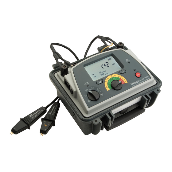
- Page 1 DLRO10HD 10 A Digital Low Resistance Ohmmeter UseR GUiDe...
-
Page 2: Safety Warnings
Disconnecting an inductive load while current is still flowing will cause a high voltage arc, which is a danger to both the user and the item under test. Although the DLRO10HD is not designed as transformer ohmmeter, it is fitted with a test in progress lamp associated with the TEST button, which indicates that current is flowing in the C1-C2 loop. - Page 3 inspection Before each use of the instrument, visually inspect the instrument case, test leads and connectors to confirm that their condition is good, with no damaged or broken insulation. Charging and mains/line operation In normal circumstances the instrument is completely safe. However, in case of an unforeseen emergency ensure instrument is positioned to allow fast disconnection of mains/line plug.
-
Page 4: Table Of Contents
Contents Safety warnings symbols used on the instrument General description Application Caution: Refer to accompanying notes Test modes HV warning Warning messages Equipment protected throughout by Double or reinforced Test techniques and applications Insulation (Class II) General operation Equipment complies with current EU Directives Electrical specifications General specifications Equipment complies with ‘C tick’... -
Page 5: General Description
A degassing safety vent is provided in the unlikely event of the battery degassing during charge. The DLRO10HD provides five test modes each of which is selected via a rotary switch. Controls are simple and easy to operate in all weather conditions and with gloved hands operation. -
Page 6: Application
■ selected to prevent heating the wire thereby changing its resistance. The DLRO10HD is well suited to measuring thick conductors, bonds and quality of welding because of its 10 A range for resistance values up to 250 mΩ. Measurements on electric motors and generators will be inductive and require the user to understand the inductive mode and charging process before a correct result is achieved. -
Page 7: Test Modes
Test modes Test mode, is selected by a six (including off) positioned rotary selector selected current through the sample continuously in one direction only. The switch that activates the following modes: instrument will take repetitive readings, which will gradually decrease to the true value as the voltage stabilises. -
Page 8: Warning Messages
‘C’ & ‘P’ indicators A good measurement requires both the current carrying circuit and the voltage detection circuit to be completed by the unit under test. DLRO10HD checks for continuity in both C and P circuits. When connectivity is detected, C 1---2 and P 1---2 indications are displayed in the left bottom sector of the LCD. -
Page 9: Test Techniques And Applications
The meaning of these lamps is described below. Green Current , 1mA, test For example, using the DH4 Duplex Handspikes with the DLRO10HD in one Complete of the AUTO test modes: Measurement fail 1. Press the TEST button on the instrument. -
Page 10: General Operation
Measurement terminals First connect the test leads to their respective measurement terminals. To simplify lead connection to the DLRO10HD the lid can be removed by lifting it to approximately 45º from closed position and sliding it to the right. Connect line power lead if line power is available. If the instrument is to... - Page 11 LCD icons After starting a test the user will see confirmation of successful continuity testing on the LCD. If the dashes are not shown connecting 1 & 2 C and/or P leads connection has not been detected. Battery icons with battery charge level indicator C 1---2 Line power connected P 1---2...
- Page 12 Power Lead and Battery Charging Battery Charge indication If the power lead supplied is not suitable for your mains connection, do not use an adaptor. Always use a power lead fitted with the correct plug. Full battery The instrument is fitted with a two-pin IEC60320 power inlet. Most power leads are made with three-core cable, so the ground connection will not Battery low be used.
-
Page 13: Electrical Specifications
electrical specifications Resistance/Current Ranges The green resistance ranges on the keypad indicate low output power (<0.25 W) outputs. Red ranges indicate higher 2.5 W (1 A) and 25 W (10 A) power outputs. Resolution and Accuracy Test current accuracy ±10% Voltmeter input impedance >200 kΩ... -
Page 14: General Specifications
-10 °C to +50 °C (14 °F to 122 °F) <90% RH Battery type 6 V, 7 Ah sealed lead acid (return instrument to a Megger authorised Reference conditions 20 ºC ±3 ºC repair agent for replacement) Storage temperature... -
Page 15: Accessories
242004-7 5.5m/18ft 242004-18 9m/30ft 242004-30 The CATIII 300 V rating on the DLRO10HD is only valid when the instrument Duplex handspikes with replaceable Needle Points ised with the optional terminal cover to provide the required creepage and 2m/7ft 242003-7 clearances at the instrument terminals. Although the terminal cover may be... -
Page 16: Repair And Warranty
Note: Any unauthorised prior repair or adjustment will automatically 2m/7ft 242021-7 invalidate the Warranty. 5.5m/18ft 242021-18 instrument Repair and spare Parts 9m/30ft 242021-30 For service requirements for Megger Instruments contact:- Current clips (2) for current connections. Megger Limited 2m/7ft 242041-7 Megger Archcliffe Road 5.5m/18ft 242041-18... - Page 17 A number of independent instrument repair companies have been approved for repair work on most Megger instruments, using genuine Megger spare The crossed out wheeled bin placed on the Megger products is a reminder parts. Consult the Appointed Distributor / Agent regarding spare parts, not to dispose of the product at the end of it’s product life with general...
- Page 18 Other technical sales offices Toronto - Canada, Sydney - Australia, Mumbai - India, Madrid - Spain and the Kingdom of Bahrain. Megger products are distributed in 146 countries worldwide. This instrument is manufactured in the United Kingdom. The company reserves the right to change the specification or design without prior notice.
Need help?
Do you have a question about the DLRO10HD and is the answer not in the manual?
Questions and answers