Table of Contents
Advertisement
MANUAL
CST 280 INVERSORA
MILLER PORTUGUES
ALUGUEL E VENDA DE MÁQUINAS DE
SOLDA E CORTE PLASMA
TODOS OS PROCESSOS DE SOLDAGEM
TRABALHAMOS EXCLUSIVAMENTE COM
AS MELHORES MÁQUINAS DO MUNDO
ASSESSORIA PARA PROCESSOS ESPECIAIS
TECNOLOGIA ATUALIZADA PARA
GARANTIR O MELHOR CUSTO BENEFÍCIO
AUMENTO DE PRODUTIVIDADE SOLDADOR-PEÇA
REDUÇÃO DE CUSTO COM ENERGIA
MIG MAG · TIG · ARCO SUBMERSO · MULTIPROCESSO · RETIFICADORAS CORTE PLASMA
INVERSORAS · ELETRODO · GERADORES DE ENERGIA · ROBÔS
www.aventa.com.br | contato@aventa.com.br
LOCAÇÃO E VENDA
MÁQUINAS DE SOLDA E CORTE
Advertisement
Table of Contents

Related Manuals for Miller CST 282


Summary of Contents for Miller CST 282
- Page 1 MANUAL CST 280 INVERSORA LOCAÇÃO E VENDA MÁQUINAS DE SOLDA E CORTE MILLER PORTUGUES ALUGUEL E VENDA DE MÁQUINAS DE SOLDA E CORTE PLASMA TODOS OS PROCESSOS DE SOLDAGEM TRABALHAMOS EXCLUSIVAMENTE COM AS MELHORES MÁQUINAS DO MUNDO ASSESSORIA PARA PROCESSOS ESPECIAIS TECNOLOGIA ATUALIZADA PARA GARANTIR O MELHOR CUSTO BENEFÍCIO...
- Page 2 OM-285986A 2020-10 Processes Stick (SMAW) Welding TIG (GTAW) Welding Description Arc Welding Power Source ™ OWNER’S MANUAL For product information, Owner’s Manual translations, and more, visit www.MillerWelds.com...
- Page 3 We know you don’t have time to do it any other way. That’s why when Niels Miller first started building arc welders in 1929, he made sure his products offered long-lasting value and superior quality.
- Page 4 MANUAL CST 280 INVERSORA LOCAÇÃO E VENDA MÁQUINAS DE SOLDA E CORTE MILLER PORTUGUES ALUGUEL E VENDA DE MÁQUINAS DE SOLDA E CORTE PLASMA TODOS OS PROCESSOS DE SOLDAGEM TRABALHAMOS EXCLUSIVAMENTE COM AS MELHORES MÁQUINAS DO MUNDO ASSESSORIA PARA PROCESSOS ESPECIAIS TECNOLOGIA ATUALIZADA PARA GARANTIR O MELHOR CUSTO BENEFÍCIO...
-
Page 5: Table Of Contents
Miller CST 282 Software Update Instructions ........ -
Page 7: Section 1 - Safety Precautions - Read Before Using
SECTION 1 – SAFETY PRECAUTIONS – READ BEFORE USING Protect yourself and others from injury—read, follow, and save these important safety precautions and operating instructions. 1-1. Symbol Usage DANGER! – Indicates a hazardous situation which, if not avoided, will result in death or serious injury. The possible hazards are shown in the adjoining symbols or explained in the text. - Page 8 HOT PARTS can burn. WELDING can cause fire or explosion. � Do not touch hot parts bare handed. � Allow cooling period before working on equipment. Welding on closed containers, such as tanks, drums, or pipes, can cause them to blow up. �...
-
Page 9: Additional Hazards For Installation, Operation, And Maintenance
� Never weld on a pressurized cylinder — explosion will result. CYLINDERS can explode if � Use only correct compressed gas cylinders, regulators, hoses, damaged. and fittings designed for the specific application; maintain them Compressed gas cylinders contain gas under high and associated parts in good condition. -
Page 10: California Proposition 65 Warnings
� Have the installation regularly checked and maintained. � Be sure all equipment in the welding area is electromagnetically compatible. � Keep high-frequency source doors and panels tightly shut, keep spark gaps at correct setting, and use grounding and shielding to �... -
Page 11: Section 2 - Consignes De Sécurité - Lire Avant Utilisation
SECTION 2 – CONSIGNES DE SÉCURITÉ - LIRE AVANT UTILISATION Pour écarter les risques de blessure pour vous-même et pour autrui — lire, appliquer et ranger en lieu sûr ces consignes relatives aux précautions de sécurité et au mode opératoire. 2-1. - Page 12 � Porter un harnais de sécurité si l’on doit travailler au-dessus du � Ne pas souder des métaux munis d’un revêtement, tels que l’acier sol. galvanisé, plaqué en plomb ou au cadmium à moins que le revête- ment n’ait été enlevé dans la zone de soudure, que l’endroit soit �...
-
Page 13: Symboles De Dangers Supplémentaires En Relation Avec L'installation, Le Fonctionnement Et La Maintenance
� Ne pas couper ou souder des jantes ou des roues. Les pneus peu- Les CHAMPS vent exploser s’ils sont chauffés. Les jantes et les roues réparées ÉLECTROMAGNÉTIQUES (CEM) peuvent défaillir. Voir OSHA 29 CFR 1910.177 énuméré dans les peuvent affecter les implants normes de sécurité. - Page 14 � Suivre les consignes du Manuel des applications pour l’équation � Lorsque cela est nécessaire pour des travaux d’entretien et de dé- de levage NIOSH révisée (Publication Nº94– 110) lors du levage pannage, faire retirer les portes, panneaux, recouvrements ou dis- manuelle de pièces ou équipements lourds.
-
Page 15: Proposition Californienne 65 Avertissements
2-4. Proposition californienne 65 Avertissements AVERTISSEMENT – Ce produit peut vous exposer à des pro- Pour plus d’informations, consulter www.P65Warnings.ca.gov. duits chimiques tels que le plomb, reconnus par l’État de Californie comme cancérigènes et sources de malforma- tions ou d’autres troubles de la reproduction. 2-5. -
Page 16: Section 3 - Definitions
Safe87 2012−07 � Complete Parts List is available at www.MillerWelds.com Only use generator outside and far away from windows, doors, and vents. SECTION 3 – DEFINITIONS A complete Parts List is available at www.MillerWelds.com Safe88 2012−07 3-1. Miscellaneous Symbols And Definitions SECTION 3 DEFINITIONS 3-2. -
Page 17: Section 4 - Specifications
Information About Default Weld Parameters And Settings NOTICE – Each welding application is unique. Although certain Miller Electric products are designed to determine and default to certain typical welding parameters and settings based upon specific and relatively limited application variables input by the end user, such default settings are for reference purposes only;... -
Page 18: Environmental Specifications
� Complete Parts List is available at www.MillerWelds.com 4-6. Environmental Specifications A. IP Rating IP Rating IP23 This equipment is designed for outdoor use. B. Temperature Specifications 4-5. Duty Cycle And Overheating 4-5. Duty Cycle And Overheating Operating Temperature Range* Storage/Transportation Temperature Range Duty Cycle is percentage of 10 Duty Cycle is percentage of 10... -
Page 19: Section 5 - Installation
� Complete Parts List is available at www.MillerWelds.com SECTION 5 – INSTALLATION Writers: Remember to move unit dimension and weight and rating la- bel location information to the appropriate sections. 5-1. Selecting A Location 1-4. Selecting a Location Do not move or operate unit where Movement it could tip. -
Page 20: Weld Output Terminals And Selecting Cable Sizes
� Complete Parts List is available at www.MillerWelds.com 5-2. Weld Output Terminals And Selecting Cable Sizes NOTICE – The Total Cable Length in Weld Circuit (see table below) is the combined length of both weld cables. For example, if the power source is 100 ft (30 m) from the workpiece, the total cable length in the weld circuit is 200 ft (2 cables x 100 ft). -
Page 21: Weld Output Terminals
� Complete Parts List is available at www.MillerWelds.com 5-4. Weld Output Terminals Turn off power before connecting to weld output terminals. Do not use worn, damaged, under- sized, or repaired cables. 1 Positive (+) Weld Output Terminal 2 Negative (−) Weld Output Terminal �... -
Page 22: Stick Dcep (Direct Current Electrode Positive) Connections
� Complete Parts List is available at www.MillerWelds.com 5-6. Stick DCEP (Direct Current Electrode Positive) Connections 1 Positive (+) Weld Output Terminal Connect work lead to negative weld output terminal. 2 Negative (-) Weld Output Terminal Connect electrode holder to positive weld output terminal. -
Page 23: Electrical Service Guide
� Complete Parts List is available at www.MillerWelds.com 5-7. Electrical Service Guide Failure to follow these electrical service guide recommendations could create an electric shock or fire hazard. These recommen- dations are for an individual branch circuit sized for the rated output and duty cycle of one welding power source. In individual branch circuit installations, the National Electrical Code (NEC) allows the receptacle or conductor rating to be less than the rating of the circuit protection device. -
Page 24: Connecting 1-Phase Input Power
� Complete Parts List is available at www.MillerWelds.com 5-8. Connecting 1-Phase Input Power Installation must meet all National and Local Codes—have only quali- fied persons make this installation. Disconnect and lockout/tagout in- put power before connecting input =GND/PE Earth Ground conductors from unit. -
Page 25: Connecting 3-Phase Input Power
� Complete Parts List is available at www.MillerWelds.com 5-9. Connecting 3-Phase Input Power Installation must meet all National and Local Codes—have only quali- fied persons make this installation. Disconnect and lockout/tagout in- put power before connecting input = GND/PE Earth Ground conductors from unit. -
Page 26: Section 6 - Operation
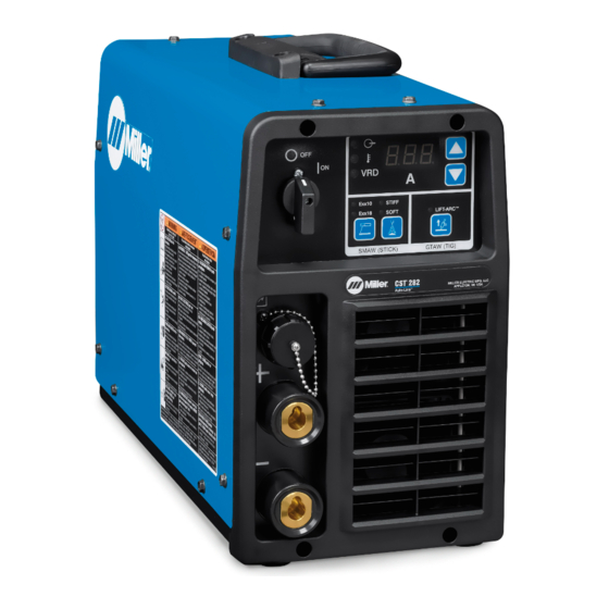
� Complete Parts List is available at www.MillerWelds.com SECTION 6 – OPERATION 6-1. Interface Controls 285215-A / Ref. m907770 5 Amps Display 9 Arc Control Select 1 Power Switch 6 Amperage Adjustment Buttons 10 Arc Control Indicator Light 2 VRD Indicator Light 7 TIG Process Select 11 Stick Process Select High Temperature Shutdown Light... -
Page 27: Interface Operation Description
� Complete Parts List is available at www.MillerWelds.com 6-2. Interface Operation Description Power Switch Use switch to turn unit and indicator light On/Off. VRD Indicator Light When the unit is configured for low open circuit voltage, this indicator light will illuminate. High Temperature When unit is first energized this indicator light illuminates for approximately 1 second to provide visual confirmation Shutdown Light... -
Page 28: Lift-Arc Start Procedure
6-6. Enabling VRD Mode � Enabling Voltage-Reducing Device (VRD) mode configures the CST 282 to operate in VRD mode using low Open Circuit Voltage (Low-OCV). � To enable the VRD Mode, visit www. millerwelds. com/support/software select CST to download the software to a USB drive. -
Page 29: Miller Cst 282 Software Update Instructions
Complete Parts List is available at www.MillerWelds.com 6-7. Miller CST 282 Software Update Instructions Visit www.millerwelds.com/support/software and select CST to download the software to a USB drive. � Most common USB drives are compatible. USB drive needs to be of format type FAT or FAT32. Larger USB drives with exFAT format are not compatible. -
Page 30: Section 7 - Maintenance
� Complete Parts List is available at www.MillerWelds.com SECTION 7 – MAINTENANCE 7-1. Routine Maintenance plete Parts List is available at www.MillerWelds.com Disconnect power before maintaining. A complete Parts List is available at www.MillerWelds.com � Maintain more often during severe conditions. SECTION 6 MAINTENANCE AND TROUBLESHOOTING �... -
Page 31: Help Displays
� Complete Parts List is available at www.MillerWelds.com 7-3. Help Displays � All directions are in reference to the front of the unit. All circuitry referred to is located inside the unit. Help 1, 6, 7 Display Indicates a malfunction in the primary power circuit. If this display is shown, contact a Factory Authorized Service Agent. - Page 32 � Complete Parts List is available at www.MillerWelds.com Help 9 Display Indicates one or both cooling fans are not operating. If this display is shown, contact a Factory Authorized Service Agent. Help 24, 25 Display Indicates machine has reached Duty Cycle limit (see Section 4-7). Unit must be left on to power the fan for cooling.
-
Page 33: Troubleshooting
� Complete Parts List is available at www.MillerWelds.com 7-4. Troubleshooting Trouble Possible Causes Remedy Place line disconnect switch in On position. (See section Line Disconnect Open. 5-8 or 5-9) No weld output, unit Check and replace line fuses, if necessary, or reset circuit completely Blown fuses. -
Page 34: Section 8 - Electrical Diagrams
SECTION 8 – ELECTRICAL DIAGRAMS Figure 8-1. Circuit Diagram For CST 282 OM-285986 Page 28... - Page 35 OM-285986 Page 29...
-
Page 36: Section 9 - Selecting And Preparing A Tungsten For Dc Or Ac Welding With Inverter Machines
SECTION 9 – SELECTING AND PREPARING A TUNGSTEN FOR DC OR AC WELDING WITH INVERTER MACHINES 9-1. Selecting Tungsten Electrode Whenever possible and practical, use DC weld output instead of AC weld output. NOTICE – Wear clean gloves to prevent contamination of tungsten. A. - Page 37 1-1. Preparing Tungsten Electrode For DC Electrode Negative (DCEN) Welding Or AC Welding With Inverter Machines Grinding the tungsten electrode produces dust and flying sparks which can cause injury and start fires. 9-2. Preparing Tungsten Electrode For DC Electrode Negative (DCEN) Welding Or AC Use local exhaust (forced ventilation) at the grinder or wear an approved respirator.
-
Page 38: Section 10 - Guidelines For Tig Welding (Gtaw)
SECTION 10 – GUIDELINES FOR TIG WELDING (GTAW) 10-1. Positioning The Torch Grinding the tungsten electrode produces dust and flying sparks which can cause injury and start fires. Use local exhaust (forced ventilation) at the grinder or wear approved respirator. Read MSDS for safety information. - Page 39 10-2. Torch Movement During Welding 1 Welding Direction Tungsten Without Filler Rod 2 Form Pool 3 Tilt Torch 4 Add Filler Metal 5 Remove Rod 6 Move Torch To Front Of Pool. Repeat Process. Tungsten With Filler Rod 10-3. Positioning Torch Tungsten For Various Weld Joints Butt Weld And Stringer Bead T Joint 20-40...
- Page 40 Notes...
-
Page 41: Warranty
Effective January 1, 2020 (Equipment with a serial number preface of NA or newer) This limited warranty supersedes all previous Miller warranties and is exclusive with no other guarantees or warranties expressed or implied. LIMITED WARRANTY − Subject to the terms and conditions Supplied Air Respirator (SAR) Boxes and Panels below, Miller Electric Mfg. - Page 42 File a claim for loss or damage during For International Locations Visit shipment. www.MillerWelds.com For assistance in filing or settling claims, con- tact your distributor and/or equipment manu- facturer’s Transportation Department. ORIGINAL INSTRUCTIONS – PRINTED IN USA © Miller Electric Mfg. LLC 2020-10...
Need help?
Do you have a question about the CST 282 and is the answer not in the manual?
Questions and answers