
Related Manuals for Miller CST 280


Summary of Contents for Miller CST 280
- Page 1 OM-217 655E 2007−01 Processes Stick (SMAW) Welding TIG (GTAW) Welding Description Arc Welding Power Source CST 280 And CST 280 VRD International Visit our website at File: Stick (SMAW) www.MillerWelds.com...
- Page 2 We know you don’t have time to do it any other way. That’s why when Niels Miller first started building arc welders in 1929, he made sure his products offered long-lasting value and superior quality.
-
Page 3: Table Of Contents
......... . 3-5. Stick (SMAW) Volt-Ampere Curves CST 280 VRD Model . -
Page 5: Section 1 − Safety Precautions - Read Before Using
SECTION 1 − SAFETY PRECAUTIONS - READ BEFORE USING som _3/05 Y Warning: Protect yourself and others from injury — read and follow these precautions. 1-1. Symbol Usage Means Warning! Watch Out! There are possible hazards with this procedure! The possible hazards are shown in the adjoining symbols. - Page 6 ARC RAYS can burn eyes and skin. BUILDUP OF GAS can injure or kill. D Shut off shielding gas supply when not in use. Arc rays from the welding process produce intense visible and invisible (ultraviolet and infrared) rays D Always ventilate confined spaces or use that can burn eyes and skin.
-
Page 7: Additional Symbols For Installation, Operation, And Maintenance
D Read Owner’s Manual before using or servic- support unit. ing unit. D If using lift forks to move unit, be sure forks are D Use only genuine Miller/Hobart replacement long enough to extend beyond opposite side of parts. unit. -
Page 8: Principal Safety Standards
1-5. Principal Safety Standards Safety in Welding, Cutting, and Allied Processes, ANSI Standard Z49.1, Boulevard, Rexdale, Ontario, Canada (phone: from Global Engineering Documents (phone: 1-877-413-5184, website: 800−463−6727 or in Toronto 416−747−4044, website: www.csa−in- www.global.ihs.com). ternational.org). Practice For Occupational And Educational Eye And Face Protection, Recommended Safe Practices for the Preparation for Welding and Cut- ANSI Standard Z87.1, from American National Standards Institute, 11 ting of Containers and Piping, American Welding Society Standard... -
Page 9: Section 2 − Consignes De Sécurité − Lire Avant Utilisation
SECTION 2 − CONSIGNES DE SÉCURITÉ − LIRE AVANT UTILISATION som _3/05 Y Avertissement : se protéger et protéger les autres contre le risque de blessure — lire et respecter ces consignes. 2-1. Symboles utilisés Symbole graphique d’avertissement ! Attention ! Cette pro- cédure comporte des risques possibles ! Les dangers éven- tuels sont représentés par les symboles graphiques joints. - Page 10 LES RAYONS D’ARC peuvent entraî- ACCUMULATIONS ner des brûlures aux yeux et à la peau. risquent de provoquer des blessures ou même la mort. Le rayonnement de l’arc du procédé de soudage génère des rayons visibles et invisibles intenses D Fermer l’alimentation du gaz protecteur en cas (ultraviolets et infrarouges) susceptibles de provo- de non-utilisation.
-
Page 11: Dangers Supplémentaires En Relation Avec L'installation, Le Fonctionnement Et La Maintenance
D Utiliser un équipement de levage de capacité D Utiliser uniquement des pièces de rechange suffisante pour lever l’appareil. Miller/Hobart. D En utilisant des fourches de levage pour déplacer l’unité, s’assu- rer que les fourches sont suffisamment longues pour dépasser du côté... -
Page 12: Principales Normes De Sécurité
2-5. Principales normes de sécurité Safety in Welding, Cutting, and Allied Processes, ANSI Standard Z49.1, Boulevard, Rexdale, Ontario, Canada M9W 1R3 (téléphone : de Global Engineering Documents (téléphone : 1-877-413-5184, site In- 800-463-6727 ou à Toronto 416-747-4044, site Internet ternet : www.global.ihs.com). www.csa-international.org). -
Page 13: Section 3 − Installation
SECTION 3 − INSTALLATION 3-1. Specifications A. 220-230/460-575 Volts Model* Welding Input Rated Welding Maximum Amperes Input At Rated Mode Power Output Amperage Open-Circuit Load Output, 50/60 Hz Dimensions Dimensions Weight Weight Range Range Voltage Voltage 280 A @ 31.2 VDC, 35.0 34.2 17.8... -
Page 14: Duty Cycle And Overheating
C. 208-230/400-460 Volts VRD Model* Welding Input Rated Welding Maximum Amperes Input At Rated Mode Power Output Amperage Open-Circuit Load Output, 50/60 Hz Dimensions Dimensions Weight Weight Range Range Voltage Voltage 280 A @ 31.2 VDC, 36.0 34.0 19.8 17.5 14.0 10.2 35 % Duty... -
Page 15: Stick (Smaw) Volt-Ampere Curves Cst 280 Model
3-3. Stick (SMAW) Volt-Ampere Curves CST 280 Model Volt-ampere curves show minimum xx10 Stick VA Curves maximum voltage amperage output capabilities of welding power source. Curves of other settings fall between curves shown. 575V Primary 208V Primary 280A STIFF 30A STIFF... -
Page 16: Tig (Gtaw) Volt-Ampere Curve Cst 280 Model
3-4. TIG (GTAW) Volt-Ampere Curve CST 280 Model Volt-ampere curves show minimum TIG VA Curve maximum voltage amperage output capabilities of welding power source. Curves of other settings fall between curves shown. DC AMPS Ref. 221 588-A OM-217 655 Page 12... -
Page 17: Stick (Smaw) Volt-Ampere Curves Cst 280 Vrd Model
3-5. Stick (SMAW) Volt-Ampere Curves CST 280 VRD Model Volt-ampere curves show minimum maximum voltage xx10 Stick VA Curves amperage output capabilities of welding power source. Curves of other settings fall between curves shown. 280A STIFF 30A SOFT 30A STIFF... -
Page 18: Tig (Gtaw) Volt-Ampere Curve Cst 280 Vrd Model
3-6. TIG (GTAW) Volt-Ampere Curve CST 280 VRD Model Volt-ampere curves show minimum TIG VA Curve maximum voltage amperage output capabilities of welding power source. Curves of other settings fall between curves shown. DC AMPS OM-217 655 Page 14... -
Page 19: Selecting A Location
3-7. Selecting A Location Line Disconnect Device Locate unit near correct input power supply. Dimensions And Weight Y Special installation may be 40 lb (18.2 kg) - with power cord required where gasoline or volatile liquids are present − see NEC Article 511 or CEC 18 in Section 20. -
Page 20: Weld Output Terminals And Selecting Cable Sizes
3-8. Weld Output Terminals And Selecting Cable Sizes* Y ARC WELDING can cause Electromagnetic Interference. To reduce possible interference, keep weld cables as short as possible, close together, and down low, such as on the floor. Locate welding operation 100 meters from any sensitive electronic equipment. Be sure this welding machine is installed and grounded according to this manual. -
Page 21: Tig Lift-Arct Dcen (Direct Current Electrode Negative) Connections
3-9. TIG Lift-Arct DCEN (Direct Current Electrode Negative) Connections Positive (+) Weld Output Terminal Connect work lead to positive weld output terminal. Negative (−) Weld Output Terminal Connect TIG torch to negative weld output terminal. Gas Cylinder Cylinder Valve Open valve slightly so gas flow blows dirt from valve. -
Page 22: Stick Dcep (Direct Current Electrode Positive) Connections
3-10. Stick DCEP (Direct Current Electrode Positive) Connections Negative (−) Weld Output Terminal Connect work lead to negative weld output terminal. Positive (+) Weld Output Terminal Connect electrode holder positive weld output terminal. 803 944-A 3-11. Electrical Service Guide CAUTION: INCORRECT INPUT POWER can damage this welding power source. -
Page 23: Selecting 208 - 230 Volts Ac Single/Three Phase Input Voltage
3-12. Selecting 208 - 230 Volts AC Single/Three Phase Input Voltage Y Turn Off welding power source, disconnect input power before proceeding. Check input voltage available at 208-230/400-460 Volts Model site. Switch Cover Voltage Selection Switch The input voltage that the power source is linked for is labeled next to the switch. -
Page 24: Selecting 400 - 575 Volts Ac Three Phase Input Voltage
3-13. Selecting 400 - 575 Volts AC Three Phase Input Voltage Y Turn Off welding power source, disconnect input power before proceeding. 208-230/400-460 Volts Model Check input voltage available at site. Switch Cover Voltage Selection Switch The input voltage that the power source is linked for is labeled next to the switch. -
Page 25: Connecting 1-Phase Input Power
3-14. Connecting 1-Phase Input Power Y Installation must meet all National and Local Codes − have only quali- fied persons make this installation. Y Disconnect and lockout/tagout in- put power before connecting input conductors from unit. Y Always connect green or green/ yellow conductor supply... -
Page 26: Connecting 3-Phase Input Power
3-15. Connecting 3-Phase Input Power Y Installation must meet all National and Local Codes − have only quali- fied persons make this installation. Y Disconnect and lockout/tagout in- put power before connecting input conductors from unit. Y Always connect green or green/ yellow conductor supply... -
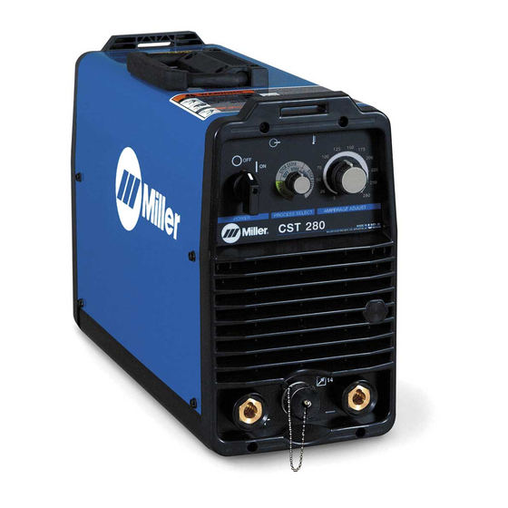
Page 27: Section 4 − Operation
SECTION 4 − OPERATION 4-1. Controls NOTE: Green on nameplate indicates a TIG Output Indicator Light Amperage Control function, Gray indicates a Stick function. When unit is first energized this indicator See Section 4-5. light flashes several times and then Power Switch High Temperature Shutdown Light illuminates continuously. -
Page 28: Process Select Control
4-2. Process Select Control Process Select Control Rotate knob to select desired process. Lift-Arct TIG - Normal open-circuit voltage is not present between electrode workpiece. A solid-state contactor does not energize until after the electrode touches the workpiece, preventing overheating, sticking, or contaminating the electrode (see Section 4-4). -
Page 29: Stick Start Procedure − Scratch Start Technique
4-3. Stick Start Procedure − Scratch Start Technique With Stick selected, start arc as follows: Electrode Workpiece Drag electrode across workpiece like striking a match; lift electrode slightly after touching work. If arc goes out electrode was lifted to high. If electrode sticks to workpiece, use a quick twist to free it. -
Page 30: Amperage Control
4-5. Amperage Control AMP ADJUST (Amperage Control) Rotate knob clockwise to increase amperage (5-280 amps). 4-6. Remote 14 Receptacle Information This unit automatically senses when a remote control is connected to the remote 14 receptacle. After connecting a remote control, the unit will automatically adjust output control to a primary/secondary configuration. In this configuration, the AMP ADJUST control on the unit becomes the primary and sets the maximum amperage output of the unit. -
Page 31: Section 5 − Maintenance And Troubleshooting
SECTION 5 − MAINTENANCE AND TROUBLESHOOTING 5-1. Routine Maintenance Y Disconnect power before maintaining. Maintain more often during severe conditions. 3 Months Replace Clean and tighten Replace Damaged unreadable weld terminals. Gas Hose labels. 3 Months Repair Or Replace Cracked Cables And Cords 6 Months Y Do not remove case when... -
Page 32: Troubleshooting
5-3. Troubleshooting Output LED (Blue) High Temperature LED (Yellow) 803 942-A Repeated LED Flashes Indicate Status Red (LED3 Blue Yellow Trouble Possible Causes Remedy on PC3) Place line disconnect switch in Line Disconnect open. on position (see Section 3-14 or 3-15). - Page 33 Repeated LED Flashes Indicate Status Red (LED3 Blue Yellow Trouble Possible Causes Remedy on PC3) Vfb leads not connected Check Vfb leads for proper wir- or reversed. ing and connection. Short circuit across out- Check for shorts. No weld output. Voltage loss.
-
Page 34: Section 6 − Electrical Diagrams
SECTION 6 − ELECTRICAL DIAGRAMS Figure 6-1. Circuit Diagram OM-217 655 Page 30... - Page 35 217 589-B OM-217 655 Page 31...
-
Page 36: Section 7 − Selecting And Preparing Tungsten Electrode
SECTION 7 − SELECTING AND PREPARING TUNGSTEN ELECTRODE gtaw 7/97 NOTE For additional information, see your distributor for a handbook on the Gas Tungsten Arc Welding (GTAW) process.Wear clean gloves to prevent contamination of tungsten electrode. 7-1. Selecting Tungsten Electrode ♦... -
Page 37: Preparing Tungsten For Ac Or Dc Electrode Negative (Dcen) Welding
7-3. Preparing Tungsten For AC Or DC Electrode Negative (DCEN) Welding Tungsten Electrode Tapered End Grind end of tungsten on fine grit, hard abrasive wheel before weld- ing. Do not use wheel for other jobs or tungsten can become contami- nated causing lower weld quality. -
Page 38: Section 8 − Parts List
SECTION 8 − PARTS LIST Hardware is common and not available unless listed. 803 947-B Figure 8-1. Main Assembly OM-217 655 Page 34... - Page 39 Quantity Model Item Part 907 251 907 244 Description Figure 8-1. Main Assembly ....221585 PANEL,FRONT W/CMPNT ....... . .
- Page 40 ....217192 NAMEPLATE,MILLER CST 280 ......
- Page 41 Quantity Model Item Dia. Part 907251 907244 907251012 Mkgs. Description Figure 8-2. Panel, Front w/Components (Continued) ... . 205764 CIRCUIT CARD ASSY,OPERATOR INTERFACE ...
- Page 42 Hardware is common and not available unless listed. 804 206-A Figure 8-4. Magnetics Subassembly Quantity Model Item Diagram Part Marking Description 907 251 907 244 Figure 8-4. Magnetics Subassembly ....206063 PANEL,PLENUM .
- Page 43 Hardware is common and not available unless listed. 803 949-B Figure 8-5. Relinking Switch And Door Assembly Quantity Model Item Dia. Part Mkgs. Description 907 251 907 244 Figure 8-5. Relinking Switch And Door Assembly ....+217252 DOOR ASSY,RELINKING .
- Page 44 Hardware is common and not available unless listed. 803 159-D Figure 8-6. Heat Sink Assembly, Output Diode Item Diagram Part Quantity marking Description Figure 8-6. Heat Sink Assembly, Output Diode ... . . 205916 HEAT SINK,DIODE OUTPUT .
- Page 45 Hardware is common and not available unless listed. 803 160 Figure 8-7. Base Assembly Item Diagram Part marking Description Quantity Figure 8-7. Base Assembly ... . . 206089 BASE, ............. .
- Page 46 Hardware is common and not available unless listed. 803 162-B Figure 8-8. Heat Sink Assembly, Input Item Diagram Part Quantity marking Description Figure 8-8. Heat Sink Assembly, Input ... . . 205915 HEAT SINK,IGBT/INPUT RECTIFIER MODULE .
- Page 47 Effective January 1, 2007 (Equipment with a serial number preface of “LH” or newer) This limited warranty supersedes all previous Miller warranties and is exclusive with no other Warranty Questions? guarantees or warranties expressed or implied. LIMITED WARRANTY − Subject to the terms and conditions...
-
Page 48: Options And Accessories
Contact the Delivering Carrier to: File a claim for loss or damage during shipment. For assistance in filing or settling claims, contact your distributor and/or equipment manufacturer’s Transportation Department. © PRINTED IN USA 2007 Miller Electric Mfg. Co. 2007−01...
Need help?
Do you have a question about the CST 280 and is the answer not in the manual?
Questions and answers
8 blue flashes