
Related Manuals for Sensidyne Gilian Gilibrator 2


Summary of Contents for Sensidyne Gilian Gilibrator 2
- Page 1 CALIBRATION SYSTEM OPERATION & SERVICE MANUAL 1000 112th Circle N, Suite 100 • St. Petersburg, FL 33716 (800) 451-9444 • (727) 530-3602 • (727) 539-0550 [FAX] • www.Sensidyne.com Revision T • Document No. 850190M...
-
Page 3: Packing List
PACKING LIST The following are shipped with the Gilian Gilibrator 2 Calibration System Standard Kits: • Control Unit Base • Flow Cell Assembly (High Flow, Standard Flow, Low Flow, or all three) • AC USB Charger with international blade kit •... -
Page 4: Notices
This manual was prepared by Sensidyne, LP exclusively for the owner of the Gilian Gilibrator 2 Calibration System. The material within this manual is the proprietary information of Sensidyne, LP and is to be used only to understand, operate, and service the instrument. By receiving this document, the recipient agrees that... -
Page 5: Table Of Contents
TABLE OF CONTENTS • PREFACE • Packing List ........................3 • Notices ........................... 4 • WARNING ........................7 SECTION ONE: INTRODUCTION Overview ....................... 8 Theory of Operation .................... 8 SECTION TWO: COMPONENTS Control Unit ......................9 2.1.1 Buttons & Indicators ................. 9 2.1.2 Display Characters .................. - Page 6 TABLE OF CONTENTS SECTION FOUR: OPERATION Start Up ........................ 21 Bubble Generation ..................... 21 Flow Readout ...................... 21 SECTION FIVE: MAINTENANCE Storage ........................ 22 Wet Cell Maintenance ..................23 5.2.1 General Maintenance ................23 5.2.2 Damper Plate Diaphragm ................ 23 5.2.3 Additional Wet Cell Maintenance ............
-
Page 7: Warning
Gilibrator 2 base, the unit will display a false SAMPLE# reading immediately after start-up. If this happens, your flow cell needs to be returned to Sensidyne to be upgraded. See Appendix C for more information. -
Page 8: Overview
SECTION ONE INTRODUCTION OVERVIEW THEORY OF OPERATION The Gilian Gilibrator 2 Calibration System is an easy- To be a primary standard, all values must be to-use Primary Standard for the calibration of air absolute and measured as absolute. A primary sampling equipment. -
Page 9: Control Unit
SECTION TWO COMPONENTS CONTROL UNIT 2.1.2 Display Characters FLOW The Control Unit (refer to Figures 2.1 & 2.2) contains a This shows the flow rate in either cubic centimeters per crystal-controlled microprocessor timing system. This minute (ccm) or liters per minute (lpm) depending on type of microprocessor, used in conjunction with the the Flow Cell Assembly used. - Page 10 Serial Port A standard, RS-232, D-Sub, 9-pin, male, connector allows the unit to be connected to a printer or a compatible sampling pump. Some air sampling pumps, such as the GilAir Plus, can calibrate themselves by receiving data from the Gilibrator 2. A special cable is required to connect the GilAir Plus docking station to the 9-pin serial port on the Gilibrator-2.
-
Page 11: Control Unit
Mounting Plate Flow Cell Connection Cable Control Unit Base Charging Indicator Display “DELETE/RESET” Serial Port Button Printer Power/Comm “ON” Button “OFF” Button Figure 2.1 Control Unit 850190M Rev T Page 11... -
Page 12: Liquid Crystal Display
Figure 2.2 Liquid Crystal Display Page 12 850190M Rev T... -
Page 13: Wet Cell Assembly
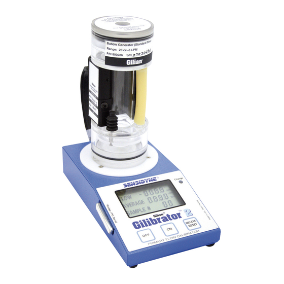
Bubble Breaker WET FLOW CELL ASSEMBLY The Bubble Breaker is a secondary chamber in the upper section of the flow cell that provides the traveling The Wet Flow Cell Assembly (refer to Figure 2.3) soap bubble a rapid expansion path. This is consists of a Bubble Generator and Sensor Block. -
Page 14: Wet Cell Assembly (Exploded View)
Damper Plate Pulsation Damper Damper Plate O-Ring Sensor Block Assembly Spacer 9- Pin Connecting Jack Bubble Breaker Plate (back) Safety Tape Air Outlet Boss Flow Tube Bubble Initiate Button Sensor Block Locking Screws (2) Safety Tape Storage Tubing Air Inlet Boss Bubble Generation Ring Base Plate O-Ring Base Plate Assembly... -
Page 15: System Set-Up
If this happens, your Cell Assembly, rotate it in a clockwise direction until flow cell needs to be returned to Sensidyne to be it “clicks” into place. The front of the Cell Assembly upgraded. See Appendix C (page 28) for more information. -
Page 16: Gilibrator 2 System Set-Up
HIGH STANDARD 9-Pin Connector Thermal Printer Battery ir 5 Flow Fault Tri-Mode Air Sampler WARNING Substitution of components may i S m u p b a s i t r it i u n t t i r o in n s o ic f c s o a m fe p ty o . -
Page 17: Cell Assembly Mounting (3-D View)
Figure 3.2 Cell Assembly Mounting (3-D View) 850190M Rev T Page 17... -
Page 18: Cell Assembly Mounting (Top View)
IMPORTANT Mounting Pins & Mounting Slots should match up Cell Assembly (base = shaded area) Mounting Slots Mounting Pins (dark area) Mounting Plate (white area) Figure 3.3 Cell Assembly Mounting (Top View) Page 18 850190M Rev T... -
Page 19: Cabling Connections
3.2.2 Cabling Connections NOTE When installing a Wet Cell on the Control Base, insert the 9-Pin Interface Plug from the Control Base If the Wet Cell Assembly is not going to be used for an extended period of time, reinstall the directly into the Connecting Jack located on the back rubber Storage Tubing between the inlet and of the Wet Cell (refer to figure 2.3). -
Page 20: Adding Soap Solution
Flow Tube Air Inlet Boss Bubble Initiate Button Bubble Generator Soap Solution Reservoir (now empty) Storage Tube Fully press & hold Bubble Initiate Button while filling reservoir Angled Edge Fill Soap Solution Reservoir until bottom of Bubble Generator Ring is immersed in the solution Figure 3.4 Adding Soap Solution (Wet Cell) -
Page 21: Start Up
SECTION FOUR OPERATION START UP FLOW READOUT Turn on the sampling source. Display The Control Unit displays the actual flow for each Depress the Bubble Initiate Button several times to sample, as well as the accumulative average flow wet the inner walls of the flow tube. You will not be rate across samples, and the current sample able to initiate a timing bubble without first “priming”... -
Page 22: Storage
SECTION FIVE SECTION FIVE STORAGE & MAINTENANCE STORAGE Long-Term The Gilibrator 2 is designed so that little maintenance is required. However, periodic cleaning, calibration and If the Gilibrator is not to be used for long periods of replacement of the Damper Diaphragm on the Wet Cell time, use the following procedures to keep the unit in Assembly may be required to ensure years of trouble- proper working order. -
Page 23: Wet Cell Maintenance
Air Outlet Boss with the plate’s largest hole. Insert re- turned to the factory annually for calibration. the spacer. Contact the Sensidyne Service Department for an RMA number, information, and pricing (refer to 6) To replace the Damper Plate assembly, moisten Appendix C). -
Page 24: Wet Cell Assembly Maintenance
Damper Plate Pulsation Damper Damper Plate O-Ring Space Bubble Breaker Plate Largest Hole Safety Tape Upper Cell Chamber Flow Tube Figure 5.1 Wet Cell Assembly Maintenance Page 24 850190M Rev T... -
Page 25: Appendix A: Parts List
APPENDIX A PARTS LIST Calibration Kits Basic: Control Unit, Battery Charger, Carrying Case, Calibration Certificate, Manual, and a Low, Standard, or High Flow Wet Cell with tubing, soap solution, and dispenser). Diagnostic: Basic kit, plus Calibration Panel. Deluxe: Basic kit, plus Printer Module and all three Wet Cells. Deluxe Diagnostic: Basic kit, plus Calibration Panel, Printer Module, and all three Wet Cells. - Page 26 APPENDIX A PARTS LIST Accessories Part Number Item/Description 800274 Printer Module Kit (115 VAC) (includes printer, paper, & cable assembly) 800274-230 Printer Module Kit (230 VAC) (includes printer, paper, & cable assembly) 700721 Printer only 811-9943-01-R PC Interface Cable only 811-0501-01 Program Disk Set only 360-0049-01...
-
Page 27: Appendix Bspecifications
APPENDIX B SPECIFICATIONS SPECIFICATIONS General Specifications Base Unit Construction ......Painted aluminum sheet metal Unit Orientation ........Base: Horizontal, on flat surface Controls ............“ON” Button “OFF” Button “DELETE/RESET” Button Indicators ..........Display (LCD) Charge Indicator (LED) Display Data ..........Flow (4-digit) Average (4-digit) Sample# (2-digit) Display Ranges ......... -
Page 28: Appendix C: Returned Material Authorization
Please indicate if a price quotation is required before RMA #: authorization of the repair cost, understanding that this The Sensidyne Service Department offers a variety of service options which will minimize costly interruptions and maintenance costs. These options include initial training, on-site technical assistance, and full factory repairs. - Page 30 1000 112th Circle N, Suite 100 • St. Petersburg, FL 33716 (800) 451-9444 • (727) 530-3602 • (727) 539-0550 [FAX] • www.Sensidyne.com...
Need help?
Do you have a question about the Gilian Gilibrator 2 and is the answer not in the manual?
Questions and answers