Table of Contents
Advertisement
Advertisement
Chapters
Table of Contents

Related Manuals for 2N Indoor View


Summary of Contents for 2N Indoor View
- Page 1 2N® Indoor View User Manual v.2.34 www.2n.com...
-
Page 2: Table Of Contents
2. Description and Installation • 2.1 Before You Start • 2.2 Quick installation guide • 2.3 Installation Conditions • 2.4 2N® Indoor View LAN Location via 2N® Network Scanner • 2.5 IP Address Lookup • 3. Configuration • 3.1 Factory Reset •... - Page 3 Indoor View is a top-quality, cost efficient and easy to install and configure answering unit. One installation can combine variable answering units manufactured by 2N Telekomunikace a.s. ® Indoor View is equipped with a specific user interface for an increased user comfort and safety. ® Indoor View basic features •...
-
Page 4: Differences Between Models And Associated Products
2N® Indoor View User Manual 1.2 Differences between Models and Associated Products ® Indoor View indoor units 2N Part No. 91378601 ® • Indoor View – black • Indoor answering audio/video unit with touchscreen Axis Part No. 02087-001 designed for all 2N IP intercoms ... - Page 5 • Indoor Touch 2.0, an elegant indoor touch panel, is designed for Axis Part No. all of the 2N IP intercoms. The display panel shows you the person 01668-001 standing at your door and helps you make conversation with the visitor, open the door lock or switch on the entrance hall lights.
- Page 6 • Indoor Touch 2.0, an elegant indoor touch panel, is designed for Axis Part No. all of the 2N IP intercoms. The display panel shows you the person 01669-001 standing at your door and helps you make conversation with the visitor, open the door lock or switch on the entrance hall lights.
- Page 7 2N IP intercoms Axis Part No. 01936-001 2N Part No. ® • Indoor Talk – black 91378401 • Indoor answering audio unit with touchscreen designed for all 2N IP intercoms Axis Part No. 01698-001 7 / 110...
- Page 8 Indoor answering audio unit with touchscreen designed for all 2N IP intercoms Axis Part No. 01699-001 Mounting Accessories 2N Part No. • Installation box for 2N indoor answering units for installation in a wall 91378800 or plasterboard. ® • Not included in the 2N Indoor View package.
-
Page 9: Terms And Symbols Used
2N® Indoor View User Manual 2N Part No. • Stand for the 2N indoor answering unit. 91378802 ® • Not included in the 2N Indoor View package. Axis Part No. 02039-001 VoIP Phones 2N Part No. 91378358 • Grandstream GXV3240 VoIP video telephone •... -
Page 10: Safety Precautions
The device may not be operated at places exposed to direct sunlight or near heat sources. ® • Indoor View is designed for indoor use. It may not be exposed to rain, flowing water, condensing moisture, fog, and so on. •... - Page 11 2N® Indoor View User Manual Caution • This product and its installation and configuration techniques are not intended for persons with diminished physical, sensory or mental capacities or persons with limited experience and knowledge unless expertly supervised or duly advised as to the use of this product by a person responsible for their safety.
-
Page 12: Description And Installation
• 2.2 Quick installation guide • 2.3 Installation Conditions • 2.4 2N® Indoor View LAN Location via 2N® Network Scanner • 2.5 IP Address Lookup 2.1 Before You Start Package Completeness Check Please check the product delivery before starting installation: Contents: ®... - Page 13 2N® Indoor View User Manual Front Layout Display Microphone Speaker Anchoring holes 13 / 110...
- Page 14 Ethernet ® Indoor View is designed for flush mounting (brick, plasterboard, wood). Use the flush mounting box (Part No. 91378800), which is not included in the package. Alternatively, the product can be mounted into a desk stand (Part No. 91378802), which is not included in the package.
- Page 15 2N® Indoor View User Manual • Before starting the mechanical installation on a selected place, make sure carefully that the preparations connected with it (drilling, wall cutting) cannot damage the electrical, gas, water and other existing wires and pipes. Cut a circular hole in the wall of the diameter of 103 mm and depth of 50 mm before installation.
-
Page 16: Quick Installation Guide
First plug the green power/ doorbell connector. Connect the LAN connector. Put the cables carefully in the pre-drilled ® Indoor View back slot to prevent them from blocking any horizontal levelling movement ® during the final installation stage. Insert 2N Indoor View in the flush mounting box making sure that it clicks onto the levelling pins, The pins allow for a 5–6 °... -
Page 17: Installation Conditions
2.3 Installation Conditions ® Make sure that the following 2N Indoor View installation conditions are met: • There must be enough space for the device installation. • The device is designed for vertical wall mounting (perpendicular to the floor) in the height of up to 120 cm above the floor. If necessary, operate the device in a position other than as... - Page 18 Use an Ethernet cable connected to a PoE supply or PoE supporting Ethernet switch/ router. PoE Supply Connection ® Use a standard straight RJ-45 terminated cable to connect 2N Indoor View to the Ethernet. The device supports the 10BaseT and 100BaseT protocols. ...
-
Page 19: Indoor View Lan Location Via 2N® Network Scanner
2N® Indoor View User Manual 2.4 2N® Indoor View LAN Location via 2N® Network Scanner ® Indoor View is configured via the administration web server. Connect the device to the LAN IP and make sure it is properly powered. ® ... - Page 20 IP address, select Config and enter the required static IP address or activate DHCP. The default configuration password is 2n. If the found device is grey highlighted, its IP address cannot be configured using this application. In that case, click Refresh to find the device again and check whether multicast is enabled in your network.
-
Page 21: Ip Address Lookup
® To find the 2N Indoor View IP address using the display, press any key on the display to quit the sleep mode. The Settings menu is displayed on the home screen after pressing the settings 21 / 110... - Page 22 Dynamic/Static IP Address Switching ® Indoor View is connected to the LAN and has to be assigned a valid IP address or obtain the IP address from the LAN DCHP server. Configure the IP address and DHCP in the System / Network menu.
- Page 23 2N® Indoor View User Manual • Static IP Address – static IP address of the device. The address is used together with the parameters below unless Use DHCP server is enabled. • Network mask – set the network mask. •...
-
Page 24: Configuration
Password: 2n Should the login screen fail to appear, you must have typed a wrong IP address/port or ® the 2N Indoor View administration web server has been switched off. To find the correct IP ® ® address, use the 2N Network Scanner as described in 2.4 2N®... - Page 25 Note • The delay after pressing RESET till the first light and sound signalling is set to 15– 35 s depending on the 2N IP intercom/answering unit model used. ® • The time interval 18 s applies to the 2N Indoor View.
- Page 26 2N® Indoor View User Manual Dynamic IP Address Setting Follow the instructions below to switch on the Static IP address mode (DCHP ON): • Press and hold the RESET button. • Wait until the red and green LEDs go on simultaneously on the device and the acoustic signal can be heard (approx.
- Page 27 2N® Indoor View User Manual 27 / 110...
- Page 28 Press the button shortly (< 1 s) to restart the system without changing configuration. Note ® • For the 2N Indoor View, the time interval between a quick press of the RESET button and reconnection of the device to the network is 20 s. 28 / 110...
-
Page 29: Software Configuration
Click the Log out button in the right-hand upper corner to log out. The start screen also provides the first menu level and quick tile navigation to selected ® Indoor View configuration sections. Some tiles also display the state of selected services. 29 / 110... - Page 30 2N® Indoor View User Manual • 3.2.1 Status • 3.2.2 Directory • 3.2.3 Services • 3.2.4 Hardware • 3.2.5 System 30 / 110...
-
Page 31: Status
2N® Indoor View User Manual 3.2.1 Status The Status menu provides clear status and other current information on the device. The menu consists of three tabs: Device, Services, Events. • 3.2.1.1 Device • 3.2.1.2 Services • 3.2.1.3 Events 3.2.1.1 Device Device The tab displays information on the model, its features, firmware and bootloader versions, etc. ... - Page 32 ACS. • Locate device – optical and acoustic signalling of a device. Optical signalling is possible ® ® ® only if the device is equipped with control backlight (2N IP Verso, 2N IP Solo, 2N IP ® ®...
- Page 33 2N® Indoor View User Manual 33 / 110...
- Page 34 2N® Indoor View User Manual 3.2.1.3 Events Events The tab displays the last 500 events captured by the device. Every event includes the capturing time and date, event type and detailed description. The events can be filtered by type in a dropdown menu above the event log.
-
Page 35: Directory
2N® Indoor View User Manual 3.2.2 Directory Directory is one of the crucial parts of the device configuration. It helps add new devices (2N IP intercoms and other answering units) and provides essential information on them. Up to 200 devices can be added to the directory. - Page 36 (accordingly, the internal/external camera button is/is not displayed during calls and call previews). With some 2N terminal equipment in the LAN, the information sent by the 2N terminal equipment is preferred to this setting (i.e. this setting is not needed for contacts using 2N terminals or camera-less devices).
- Page 37 2N® Indoor View User Manual • Start call with a doorbell button press – a phone call to this device will be set up after the alarm call button is pressed. Set the doorbell alarm call function in HW / Digital inputs / Doorbell button.
-
Page 38: Services
2N® Indoor View User Manual 3.2.3 Services Here is what you can find in this section: • 3.2.3.1. Phone • 3.2.3.2 Unlocking • 3.2.3.3 HTTP Command • 3.2.3.4 User Sounds • 3.2.3.5 Web Server • 3.2.3.6 Weather 38 / 110... - Page 39 Audio – audio codec, DTMF and other audio stream parameter transmission settings. • Video – video codec and SDP codec settings. • 2N Indoor Units – general parameters and count of identified LAN devices. SIP 1 and SIP 2 ® Indoor View helps you configure one SIP account.
- Page 40 2N® Indoor View User Manual • Display Name – set the name to be displayed as CLIP on the called party's phone. • Phone Number (ID) – set your device phone number (or another unique ID composed of characters and digits). Together with the domain, this number uniquely identifies the device in calls and registration.
- Page 41 2N® Indoor View User Manual • Proxy Address – set the SIP Proxy IP address or domain name. • Proxy Port – set the SIP Proxy port (typically 5060). • Backup Proxy Address – set the backup SIP Proxy IP address or domain name. The address is used where the main proxy fails to respond to requests.
- Page 42 2N® Indoor View User Manual • SIP Transport Protocol – set the SIP communication protocol: UDP (default), TCP or TLS. • Lowest Allowed TLS Version – set the lowest TLS version to be accepted for device connection. • Verify Server Certificate – verify the SIP server public certificate against the CA certificates uploaded in the device.
- Page 43 2N® Indoor View User Manual • IP Address Filter Enabled – enable the blocking of SIP packet receiving from addresses other than SIP Proxy and SIP Registrar. The primary purpose of the function is to enhance communication security and eliminate unauthorized phone calls.
- Page 44 2N® Indoor View User Manual • Call Answering Mode (SIP 1, SIP 2) – set the way of receiving incoming calls. The following three options are available: • Always busy – the device rejects incoming calls. • Manual answering – the device rings to signal incoming calls and the user can press a keypad button to pick up.
- Page 45 2N® Indoor View User Manual • Automatic Image Count – set the count of snapshots that shall be automatically taken during a call and saved into the call log. Caution • If the Save Image during Call function is disabled, all the snapshots will be deleted but the call logs will be preserved. ...
- Page 46 2N® Indoor View User Manual Audio Enable/disable the use of audio codecs for call setups and set their priorities. The tab below helps you define how DTMF characters shall be sent from the intercom. Check the opponent’s DTMF receiving options and settings to make the function work properly.
- Page 47 2N® Indoor View User Manual In-Band (Audio) – enable classic DTMF dual tone receiving in the audio band. RTP (RFC-2833) – enable DTMF receiving via RTP according to RFC-2833. SIP INFO (RFC-2976) – enable DTMF receiving via SIP INFO messages according to RFC-2976.
- Page 48 LAN devices cannot locate this device, i.e. cannot call the device in the device:device_ID format. Device ID – set the device ID to be displayed in the LAN device list in all the 2N devices in one and the same LAN. You can direct a call to this device by setting the user phone number as device:device_ID in these devices. ...
- Page 49 Show LAN devices list – display a detailed list of local devices in the network. 3.2.3.2 Unlocking ® Unlocking is another function of 2N Indoor View, which sets the remote door unlocking parameters. • Default Unlock Code – use this code when a call has been set up with a device/phone number that is not added to the unit phone book.
- Page 50 ® HTTP Command on the 2N Indoor View answering unit helps you send up to 3 selected HTTP commands by a button press. The buttons are displayed on the Home page under the selected icon in case the function is set.
- Page 51 3.2.3.4 User Sounds ® Indoor View signals variable operational statuses with a sequence of tones. If the standard signaling tones do not meet your requirements, you can modify them. The device allows you to modify sound signaling for the following states:...
- Page 52 2N® Indoor View User Manual • Doorbell – set the tone to be played when the doorbell is used. Sound Upload You can upload up to 10 user sound files to the device and name each of them for better orientation. Press to upload a sound file to the device.
- Page 53 The HTTPS protocol is used for the browser - device communication. Enter the login user name and password first. The default values are admin and 2n respectively. We recommend to you change the default password as soon as possible.
- Page 54 2N® Indoor View User Manual • HTTP Port – set the web server port for HTTP communication. The port change will not be applied until the device is restarted. • HTTPS Port – set the web server port for HTTPS communication. The port change will not be applied until the device is restarted.
- Page 55 2N® Indoor View User Manual 3.2.3.6 Weather The Weather service offers display of information about the current weather for the selected ® location on the 2N Indoor View home screen. • Show Weather – display information about the current weather on the device.
- Page 56 2N® Indoor View User Manual • Location Found – weather forecast location found by the weather service. • Country – country of the automatically defined or completed location. 56 / 110...
-
Page 57: Hardware
2N® Indoor View User Manual 3.2.4 Hardware Here is what you can find in this section: • 3.2.4.1 Audio • 3.2.4.2 Display • 3.2.4.3 Digital Inputs 57 / 110... - Page 58 3.2.4.1 Audio ® Indoor View is equipped with a speaker. Set the phone call and state signaling volume control in this configuration section. Master Volume controls the general device volume including call volume, signaling tone volume, and so on. Consider the noise level of the ambient environment while setting this parameter.
- Page 59 2N® Indoor View User Manual • Warning Tone Volume – set the volume of warning and signaling tones. The volume values are relative against the set master volume. • Suppress Warning Tones – suppress signaling of the following operational states: Internal application started, IP address received and IP address lost.
- Page 60 2N® Indoor View User Manual • Language – set the language for the texts to be displayed. Choose one of the seven pre- defined languages (CZ, EN, DE, FR, ES, IT, RU). • Date Format – set the date format to be displayed.
- Page 61 2N® Indoor View User Manual Note If none of the pre-defined languages is convenient for you, proceed as follows: • Download the original language file (English). • Modify the file using a text editor (replace the English texts with your own ones).
- Page 62 2N® Indoor View User Manual 3.2.4.3 Digital Inputs This subsection describes the digital input options of the device. • Doorbell Button Function – select doorbell function (doorbell, alarm call). The button is used either as a classical doorbell or for alarm call activation. ...
-
Page 63: System
2N® Indoor View User Manual 3.2.5 System Here is what you can find in this section: • 3.2.5.1 Network • 3.2.5.2 Date and Time • 3.2.5.3 Certificates • 3.2.5.4 Auto Provisioning • 3.2.5.5 Syslog • 3.2.5.6 Maintenance 63 / 110... - Page 64 3.2.5.1 Network ® Indoor View is connected to the LAN and has to be assigned a valid IP address or obtain the IP address from the LAN DCHP server. The Network section helps you configure the IP address and DHCP. ...
- Page 65 2N® Indoor View User Manual List of Parameters Basic • Use DHCP server – enable automatic obtaining of the IP address from the LAN DHCP server. If the DHCP server is unavailable or otherwise inaccessible in your LAN, use the manual network settings.
- Page 66 2N® Indoor View User Manual • VLAN Enabled – enable the virtual network support (VLAN according to 802.1q). Remember to set the VLAN ID too. • VLAN ID – choose a VLAN ID from the range of 1–4094. The device shall only receive packets with the set ID.
- Page 67 2N® Indoor View User Manual 801.1x • Device Identity – username (identity) for authentication via EAP-MD5 and EAP-TLS. • MD5 Authentication Enabled – enable authentication of network devices via the 802.1x EAP-MD5 protocol. Do not enable this function if your LAN does not support 802.1x. If you do so, the intercom will become inaccessible.
- Page 68 2N® Indoor View User Manual the LAN. Choose one of three sets of user certificates and private keys; refer to the Certificates subsection. 68 / 110...
- Page 69 Password – enter the access password for PEAP-MSCHAPv2 authentication. Trace ® The Trace tab helps you trigger capturing of incoming and outgoing packets via the 2N Indoor View LAN interface. The captured packets are stored in a 4 MB buffer. When the buffer storage capacity is full, the oldest packets are rewritten automatically.
- Page 70 2N® Indoor View User Manual 3.2.5.2 Date and Time ® Indoor View is equipped with a real time clock to back up the device for even a few days in ® case of power outage. Click Synchronise to synchronise your 2N Indoor View time with your...
- Page 71 2N® Indoor View User Manual List of Parameters • Synchronize with browser – click the button to synchronize the device time with your current PC time value. • Automatic Detection – define whether the time zone shall be detected automatically from My2N. In case automatic detection is disabled, the Manual selection parameter is Used (manually selected time zone or Own rule).
- Page 72 802.1x (EAP-TLS) SIPs ® Indoor View allows you to download up to 3 sets of certificates from certification authorities, which help you authenticate the communicating device, and also 3 user certificates and private keys for encryption purposes. Each certificate requiring service can be assigned one certificate set, refer to the Web Server, E- mail and Streaming subsections.
- Page 73 2N® Indoor View User Manual Note ® • If you use the Self Signed certificate for encryption, the 2N Indoor View web server – browser communication is secure, but the browser notifies you that it cannot ® authenticate the 2N Indoor View certificate.
- Page 74 2N® Indoor View User Manual Click to upload a certificate saved on your PC. Select the certificate (or private key) file in a ® dialogue window and click Upload. Press to remove a certificate from 2N Indoor VIew. Caution •...
- Page 75 3.2.5.4 Auto Provisioning ® The 2N Indoor View help you update firmware and configuration manually, or automatically from a storage on a TFTP/HTTP server selected by you according to predefined rules. ® The TFTP and HTTP server addresses can be configured manually. The 2N Indoor View support automatic identification of the local DHCP server address (Option 66).
- Page 76 2N® Indoor View User Manual • Active Profile – select one of the pre-defined profiles (ACS), or choose a setting of your own and configure the ACS connection manually. • Next Synchronization in – display the time period in which the device shall contact a remote ACS.
- Page 77 3.2.5.5 Syslog ® Indoor View allows you to sends syslog messages including relevant device state and process information to a syslog server for recording and further analysis or auditing of the device observed. It is unnecessary to configure this service for common operations.
- Page 78 2N® Indoor View User Manual General overview of local syslog messages. 78 / 110...
- Page 79 2N® Indoor View User Manual 3.2.5.6 Maintenance This menu helps you maintain the device configuration and firmware. You can back up and restore all the parameters, upgrade firmware and/or factory reset the device. • Restore Configuration – restore configuration from a previous backup. Press the button to display a dialogue window to select a configuration file and upload it to the device.
- Page 80 The whole upgrading process takes less than one minute. Download the current firmware version for your device from www.2n.com. FW upgrade does not affect configuration The device checks the firmware file and prevents you from uploading an incorrect or corrupt file.
- Page 81 • Send anonymous statistics data – enable sending of anonymous statistic data on device usage to the manufacturer. No such delicate information as passwords, access codes or phone numbers are included. This information helps 2N TELEKOMUNIKACE a.s. improve the software quality, reliability and performance. You can participate in this voluntarily and cancel your statistic data deliveries any time.
-
Page 82: Device Control Via Display
2N® Indoor View User Manual 4. Device Control via Display Sleep Mode Home Page The device will automatically go into the sleep The Home page is set as the introductory mode if there is no activity (after selection of a screen, which is displayed when the device timeout between 15 s and 10 min). - Page 83 2N® Indoor View User Manual Icon Description DND mode Device configuration Call list Incoming call ringtone volume up Incoming call ringtone volume down Incoming call ringtone volume mute Value up Value down Microphone mute in call Locked, screen lock Unlocked, screen lock activated/deactivated...
- Page 84 2N® Indoor View User Manual Icon Description Move up Move down 84 / 110...
-
Page 85: Call Log
(outgoing/incoming/missed) and information on from/to which destination the call was made. The maximum call count is 20. ® You can choose any of the following actions from the 2N Indoor View call list: • Return to Home page using the left-hand upper button •... -
Page 86: Directory
Press the eye button to show the camera preview (the button is only available if the device is equipped with a ® camera). The camera preview option is based on the 2N Enhanced Video license of the selected device. Click the lock button to open the door during an incoming/outgoing call for the selected device. -
Page 87: Settings
2N® Indoor View User Manual • The camera switching function is only displayed if it has been activated and properly configured in the intercom. Set the Directory via the web interface in the Directory / Device section. You can add a device... - Page 88 2N® Indoor View User Manual • Screen timeout – timeout after which the device automatically goes into the Sleep mode if there is no activity. • Ringtone volume – set the incoming call ringtone volume. • Call volume – set the phone call volume.
- Page 89 2N® Indoor View User Manual • Set date and time automatically – activate a mode in which the date and time will be taken from the network. • Set date – set the date manually. • Set time – set the time manually.
- Page 90 2N® Indoor View User Manual • Screen lock – switch the screen lock or also the so-called parental lock on/off. Enter the PIN code to enable the screen lock. Enter the same PIN code to disable the screen lock. •...
- Page 91 2N® Indoor View User Manual • Show weather – display or hide information about the current weather on the Home page. • Location – device location for weather forecast. Press the Home page weather area shortly to set the location in the Weather / Settings section, which will be displayed automatically.
- Page 92 2N® Indoor View User Manual This section provides basic information on the device (serial number, MAC address, FW version, IP address, My2N ID). 92 / 110...
-
Page 93: Operational Statuses
2N® Indoor View User Manual 5. Operational Statuses This section describes the user scenarios and states that may occur during operation, including the user options and expected results of actions. Status and Description User Actions Navigation Actions and Result Sleep Mode Only the current date, time and weather are shown on the display. - Page 94 2N® Indoor View User Manual Status and Description User Actions Navigation Actions and Result Home Page The device is in the relax mode. Display Directory Press the blue The list of all available backlit phone devices is displayed. earpiece button...
- Page 95 Detail in list The display shows a snapshot from the camera set in the 2N IP intercom if a camera-equipped device initiated the call. A device symbol is displayed if the call initiating device is not equipped with a camera. Furthermore, the call day, date and time, description of the calling/called device and call status (outgoing/ incoming/missed) are displayed.
- Page 96 2N® Indoor View User Manual Status and Description User Actions Navigation Actions and Result Directory The device displays a list of destinations that can be called. The destinations include their names and the device type they are equipped with. Return to Home Press back Home page is displayed.
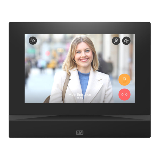
- Page 97 2N® Indoor View User Manual Status and Description User Actions Navigation Actions and Result Incoming Call The device is playing the selected ringtone. The display shows the camera view if available, CLIP and Incoming call message. Pick up call...
- Page 98 2N® Indoor View User Manual Status and Description User Actions Navigation Actions and Result Outgoing Call The device is playing the ringtone. The display shows the camera view if available, called device ID and Outgoing call message. End call Press the call end...
- Page 99 2N® Indoor View User Manual Status and Description User Actions Navigation Actions and Result In Call The display shows the camera view if available, or the called device ID if no camera is available. A timer is running at the view.
- Page 100 2N® Indoor View User Manual Status and Description User Actions Navigation Actions and Result Save camera The snapshot is saved in Press the snapshot manually the call log detail. The log button to save can contain several the snapshot snapshots.
- Page 101 2N® Indoor View User Manual Status and Description User Actions Navigation Actions and Result Incoming call in Do The device does not play the selected ringtone. The display shows Not Disturb mode the camera view if available, CLIP and Incoming call message.
- Page 102 2N® Indoor View User Manual 7. Technical Parameters Power Supply • Type: 12 V DC +/−10 % adapter or PoE 802.3af • Recommended power supply: 12 V / 1 A • Polarity reversal protection: yes Power Consumption • In idle: • 12 V: 2,28 W – 0,19 A •...
- Page 103 2N® Indoor View User Manual • Operating temperature: 0 to 50 °C • Relative humidity: 10 to 90 % non-condensing • Storing temperature: −20 to 70 °C • Recommended altitude: 0–2000 m 103 / 110...
-
Page 104: Maintenance - Cleaning
2N® Indoor View User Manual 6. Maintenance – Cleaning If used frequently, the device surface gets dirty. Use a piece of soft cloth moistened with clean water to clean the device. You are recommended to follow the principles below while cleaning: Do not use aggressive detergents (such as abrasives or strong disinfectants). -
Page 105: Supplementary Information
2N® Indoor View User Manual 8. Supplementary Information ® This section provides supplementary information on the 2N Indoor View product. Here is what you can find in this section: • 8.1 Troubleshooting • 8.2 Directives, Laws and Regulations – General Instructions and Cautions ... -
Page 106: Troubleshooting
For the most frequently asked questions refer to faq.2n.cz. 8.2 Directives, Laws and Regulations – General Instructions and Cautions ® Indoor View conforms to the following directives and regulations: • 2014/35/EU for electrical equipment designed for use within certain voltage limits •... - Page 107 či zařízení v rozporu s pokyny, návodem či doporučením výrobce, popř. použitím s nevyhovujícími produkty či zařízeními jiných výrobců, zákazník souhlasí s tím, že společnost 2N TELEKOMUNIKACE a.s. není odpovědná za jakékoli omezení funkčnosti takového produktu ani za újmu související s takovým případným omezením funkčnosti.
- Page 108 2N® Indoor View User Manual Please read this User Manual carefully before using the product. Follow all instructions and recommendations included herein. Any use of the product that is in contradiction with the instructions provided herein may result in malfunction, damage or destruction of the product.
- Page 109 2N® Indoor View User Manual Electric Waste and Used Battery Pack Handling Do not place used electric devices and battery packs into municipal waste containers. An undue disposal thereof might impair the environment! Deliver your expired electric appliances and battery packs removed from them to dedicated dumpsites or containers or give them back to the dealer or manufacturer for environmental- friendly disposal.
- Page 110 2N® Indoor View User Manual 110 / 110...
Need help?
Do you have a question about the Indoor View and is the answer not in the manual?
Questions and answers